Note: Descriptions are shown in the official language in which they were submitted.
CA 02679428 2009-08-28
1
Device for Mass Transfer and/or Energy Exchange
The invention relates to a device for the mass transfer and/or energy exchange
between two media, particularly between blood and a gas/gas mixture,
comprising a
chamber through which the first medium flows and in which at least one mass
and/or
energy-permeable hollow fiber is disposed, preferably a plurality of mass
and/or
energy-permeable hollow fibers are disposed, through which a second medium can
flow through and around which the first medium can flow.
Generic devices of this type are used, for example, in medical technology, and
there
in particular in applications for blood purification, such as dialysis, blood
separation or
also artificial lungs (oxygenators).
In the field of application of oxygenators, it is provided to this end to
allow the blood
as a first medium to flow through a chamber, in which at least one mass and/or
energy-permeable hollow fiber is disposed, or in a preferred embodiment a
plurality
of mass and/or energy-permeable hollow fibers are disposed, through which the
second medium, in this case particularly oxygen can flow, and around which the
first
medium flows.
If in this version blood that originated from the body of a living being and
is aerated
with CO2 is pumped through the chamber, the different partial pressures of
oxygen
and CO2 on the two sides of the mass and/or energy-permeable hollow fiber
produce
a mass transfer in the sense that CO2 is removed from the blood and the same
is
oxygenated with oxygen from the hollow fibers. In this way, such a device can
operate as an artificial lung and assume, for example, the lung function of a
patient,
either partially or also completely.
Insofar as an oxygenator, which is to say an artificial lung, is described in
more detail
in this specification, it shall not be interpreted as a restriction, but only
as an
application by way of example. The device according to the invention described
below can in principle be use for the mass transfer and/or energy exchange
between
arbitrary media, and not only in medical technology, but also in other
industrial
applications.
CA 02679428 2009-08-28
2
In order to achieve adequate and defined flow rates of a first medium through
the
afore-mentioned chamber, in particular of the blood through the chamber,
external
pumps are required. In the range of applications of the oxygenators, this
means that
in addition to the generic device an external pump must be provided, which is
used to
ensure that blood is pumped from the body of a patient through the device and
then
back into the body of the patient. In this respect, the body of a patient
shall denote
both the body of a human and that of an animal patient.
When looking overall at the generic devices and the externally employed pumps,
this
principle mentioned above causes a significant volume which must be filled by
the
first medium, in this application the blood, for example.
Particularly with babies, and specifically premature babies, who have a very
low
blood volume, at times less than 100 milliliters, this means that the generic
known
devices cannot be employed, or great stress is caused to the organism of a
baby by
the addition of donor blood, blood plasma, or plasma expander, in order to be
able to
fill the volumes of the known devices. Furthermore, the use of such generic
known
devices is also possible only outside the body of a patient due to the
additional
pumps.
It is the object of the invention to refine a generic known device such that a
compact
version is achieved, particularly one that requires a minimal filling volume
and
moreover also opens up the use as an implantable device.
This object is achieved by a device of the generic type mentioned above, a
pump
function being provided in the afore-mentioned chamber.
For this purpose, for example, a pump element can be integrated in the device,
particularly in the chamber, for example by at least one deformable,
particularly
elastically deformable element, the surface/volume of which can be varied at
least in
some regions such that in the case of a surface/volume increase the first
medium can
be displaced from the chamber, and in the case of a surface/volume reduction
the
first medium can be suctioned into the chamber.
The essential core idea of this aspect according to the invention is that with
this
CA 02679428 2009-08-28
3
version a pump function can be integrated directly in the device, thereby
eliminating
an extracorporeal additional pump. The pump effect is achieved in that due to
the
increase in the surface of a deformable, particularly elastically deformable
element,
and the associated volume increase, the first medium present in the afore-
mentioned
chamber, such as blood, is automatically displaced, and with a subsequent
surface or
volume decrease of this element, the first medium, which is to say blood, for
example, is again suctioned into the chamber due to the resulting negative
pressure.
To this end, it must be ensured that the process of displacement always causes
the
first medium treated as desired by the mass transfer and/or energy exchange to
be
displaced, and during suctioning the untreated medium to be suctioned.
This can be achieved in that a flow direction through the chamber is defined,
which in
a preferred embodiment of the invention can take place in that in the flow
path at
least one one-way valve is disposed, and preferably that in the chamber at the
inlet
and at the outlet for the first medium each a one-way valve is disposed.
The first medium can flow through such a valve only in one direction, so that
in a
version having two valves the suctioning of the first medium can always take
place
through the one valve and the displacement of the first medium can always take
place through the other valve. The arrangement of these valves directly in the
chamber, or at the inlet or outlet of the chamber, thus results further in a
reduction of
the size and in a preferred compactness of the device according to the
invention,
since such means for defining the flow direction in this case no longer have
to be
provided externally.
The deformable element can be controlled, for example, from outside the
device, for
which different measures are available. For example, it may be provided that
the
deformable element solely changes the shape thereof, and consequently the
surface
size or the volume thereof, in that it is controlled electrically or
electronically and/or
hydraulically and/or pneumatically.
For example, the deformable element may be configured as a balloon and thereby
form an inflatable and deflatable envelope, which additionally can also be
designed to
be elastic. In this way, the pump effect can be achieved, for example, through
periodic filling and emptying by means of a fluid (gas or liquid).
CA 02679428 2009-08-28
4
In a particularly preferred embodiment, it may also be provided that the at
least one
deformable element is configured as a deformable, particularly elastically
deformable
hollow fiber, the surface/volume of which can be varied at least in regions by
inner
pressurization with a medium. For example, if such a particularly elastic
hollow fiber
is filled by a fluid medium, such as a gas or also a liquid, then by varying
the pressure
of this medium it can be achieved that the surface, and consequently the
volume
taken up by the hollow fiber in the chamber, is increased. In this way too,
the desired
pump effect according to the invention can be achieved. Furthermore, by
generating
a negative pressure inside the hollow fiber, the volume in the chamber can be
increased. In this way, by subjecting the hollow fiber to pressure, an
increased
"stroke volume" can be achieved.
According to one embodiment of the invention, it may be provided that in the
device
mass and/or energy-permeable hollow fibers are provided, particularly at least
one
that is used only for the mass transfer and/or energy exchange, and that at
least one
elastically deformable hollow fiber is used, which is integrated in the device
for the
pump purposes. To this end, one or more of the hollow fibers used for mass
transfer
or energy exchange can be used, and the also applies to the hollow fiber that
is used
for the pump purposes. The mass and/or energy-permeable hollow fibers can also
be
rigid hollow fibers.
In another preferred embodiment, it may also be provided that the at least one
elastically deformable hollow fiber is configured as a mass and/or energy-
permeable
hollow fiber. For example, for this purpose an elastically deformable and mass
and/or
energy-permeable hollow fiber can be configured as a silicone hose, since
silicone,
particularly in the application as an oxygenator, is permeable to oxygen and
carbon
monoxide such that not only the gas exchange between the gas phase and the
blood
phase of a device according to the invention can be carried out through a
silicone
hose, but also that the pump function can be implemented due to the elastic
deformation property.
In a particularly simple and accordingly compact and cost-effective
embodiment, it
can thus be provided that a device has only a single, particularly elastically
deformable and simultaneously mass and/or energy-permeable hollow fiber, which
both assumes the pump function of the first medium, and transports the second
CA 02679428 2009-08-28
medium, by means of which a mass transfer and/or energy exchange is to take
place. Of course, instead of a particularly elastically deformable and mass
and/or
energy-permeable hollow fiber, it is also possible to use an arbitrary number
of
energy-permeable deformable hollow fibers. The device may then comprise only
hollow fibers of the elastic and permeable type. In this embodiment, it may
therefore
be provided that the medium for pressurization of the at least one elastically
deformable hollow fiber corresponds to the second medium.
In another embodiment, it may also be provided that at least some of all mass
and/or
energy-permeable hollow fibers are also configured as elastically deformable
hollow
fibers. In such an embodiment, for example, there may be mass and/or energy-
permeable hollow fibers, which are configured as rigid hollow fibers, as well
as mass
and/or energy-permeable hollow fibers, which are elastically deformable, as
mentioned above. To this end, one or more of each type of the hollow fibers
may be
provided.
In yet another embodiment, the elastically deformable hollow fibers can be
used
solely for pump purposes, particularly without them being mass-permeable, but
optionally being energy-permeable.
Accordingly, particularly in the last embodiments having two different types
of hollow
fibers (pump fibers and mass transfer fibers), it may be provided that the
medium for
pressurization of the at least one elastically deformable hollow fiber, which
is to say
the medium used for implementing the pump function, does not correspond to the
second medium, but is formed by yet another fluid medium, such as a gas or a
liquid.
To this end, it may additionally be provided that through the use of this
medium also
a heat exchange with the first medium is implemented.
This is particularly advantageous, for example, in the use for blood
oxygenators,
since here, in addition to the pump effect, which is implemented by the other
or
additional medium, it can also be ensured that sufficient thermal energy is
transmitted
to the first medium, in this application it being the blood, in order to
maintain the body
temperature of the patient. Since the first medium, in this application it
being the
blood, flows around the hollow fiber at least in the region of the elastic
hollow fiber in
which a surface or volume increase takes place, accordingly at the same time a
thermal energy transfer to the first medium can take place.
CA 02679428 2009-08-28
6
The generation of a pump function inside the chamber of the device, through
which
the first medium flows, which is to say blood, for example, in addition to the
pure
pump effect also has the added advantage that a disturbance is caused by the
pressure fluctuations in the chamber, whereby a plasma edge, which may form on
the chamber side on the mass-permeable hollow fibers, can be destroyed or at
least
disturbed, in order to optimize the efficiency of the mass and/or energy
transfer.
In a further preferred embodiment according to the invention, it may also be
provided
that, in addition to the above-mentioned chamber, through which the first
medium
flow, at least one other chamber is provided, by way of which the second
medium is
fed to the at least one mass and/or energy-permeable hollow fiber, preferably
to the
plurality of mass and/or energy-permeable hollow fibers, wherein the at least
one
elastically deformable hollow fiber extends through the above-mentioned and
the at
least one further chamber.
This produces the advantage that due to the extension of the deformable fiber
also
through the other chamber optionally also a heat exchange, particularly a heat
transfer to the second medium, can take place such that a heat transfer after
heating
of the second medium can also take place by way of the mass-permeable hollow
fibers to the first medium.
Furthermore, the embodiment may be such that the surface/the volume of the at
least
one particularly elastically deformable hollow fiber can also be varied at
least in some
regions in the at least one other chamber by inner pressurization with the
medium,
such that in the case of a surface/volume change pressure fluctuations can be
generated in the second medium. These pressure fluctuations can advantageously
cause a gas boundary layer, which forms by the phase of the second medium or
by
the gas phase on the mass-permeable hollow fiber, is disturbed or destroyed,
thereby
improving or optimizing the mass transfer and/or energy exchange.
In all embodiments mentioned above, be it with only one or also several
chambers, it
may be provided that the surface/volume change of the at least one
particularly
elastically deformable hollow fiber can be generated by pressure changes of
the
medium flowing through this hollow fiber.
CA 02679428 2009-08-28
7
To this end, as mentioned above, it can be a fluid medium, such as a gas or
also a
liquid. The pressure changes can be generated by a continuous inflow of this
medium
into the at least one particularly elastically deformable hollow fiber at the
inlet into the
device, and an outflow, the quantity of which can be controlled, at the outlet
of the
device, particularly by a cross-section that can be varied in a controlled
manner.
For example, the controllably variable cross-section at the outflow can be
reduced in
a target manner, or even be closed, whereby with a continuous inflow on the
inlet
side the pressure in the particularly elastically deformable hollow fiber is
increased,
wherein due to the elastic deformation the volume taken into the chamber is
increased and the first medium, in this case particularly blood, is displaced.
If the
controllably variable cross-section is increased, particularly after prior
closure, the
pressure is reduced, for example by an elastically restoring force, and the
volume of
the hollow fiber can be reduced such that the originally displaced volume of
the first
medium is compensated for by the subsequent suctioning of first medium into
the
chamber.
In all embodiments, it may be provided that a particularly elastically
deformable
hollow fiber can be deformed across the entire length thereof, which it takes
up in the
at least one chamber of the device. In another embodiment, it may also be
provided
that the variation of the surface size or of the volume intentionally is
limited to only
certain regions, particularly at least one region of the elastically
deformable hollow
fiber. For example, in order to generate at least one locally delimited region
of this
surface or volume change, a deformable, particularly elastic, hollow fiber can
have at
least one supporting element surrounding the same at least partially. Such a
supporting element can be, for example, a ring, a tube, or also a lattice,
which
surrounds the elastic hollow fiber at least partially such that in the
surrounded region
no volume or surface increase can take place, but only in the regions that
remain free
of the supporting element.
In another embodiment, it may also be provided that for the generation of at
least one
locally delimited region of the surface or volume variation an elastic hollow
fiber has a
regionally variable wall thickness and/or a surface profile. If, for example,
the wall
thickness is reduced in a certain region compared to other regions, then the
elastic
hollow fiber will tend to significantly bulge in this thickness-reduced region
due to the
pressure increase acting from inside the fiber.
CA 02679428 2009-08-28
8
With all these above-mentioned measures, the displacement volume of an elastic
hollow fiber can therefore be precisely defined.
In addition, it may also be provided that a particularly elastically
deformable hollow
fiber is disposed, for example, in a cage, which limits the maximum displaced
volume. For example, during an inflation of a hollow fiber, the fiber can
expand only
so much and increase the volume thereof until the wall regions of the elastic
hollow
fiber rest against the inside regions of the surrounding cage. The hollow
fiber is then
supported by the cage and cannot expand any further, so that the effectively
displaced volume is determined by the maximum volume of the surrounding cage.
It is also possible that a hollow fiber comprises a section that cannot be
elastically
deformed and that cannot be elastically inflated by inner pressurization, such
as in
the manner of a plastic bag, until the maximum volume of this region has been
reached. Upon a decrease in pressure, this region can again actively collapse,
particularly folded, by restoring forces, particularly spring forces. To this
end, for
example spring elements (at least one) can be disposed in the wall of the
deformable
section.
The arrangement of the at least one particularly elastically deformable hollow
fiber
and the mass and/or energy-permeable hollow fibers, which optionally according
to
one embodiment can also be identical to each other, can in principle be
arbitrary.
According to the invention, however, it is found to be particularly
advantageous if at
least one elastically deformable hollow fiber is surrounded by a plurality of
non-elastic
and mass and/or energy-permeable hollow fibers, particularly in a symmetrical
manner. Again, the surrounded deformable hollow fiber can likewise be
configured to
be mass and/or energy-permeable, or optionally may only be provided for the
pump
function. This arrangement can preferably be configured such that the overall
arrangement of hollow fibers has a substantially polygonal, particularly
hexagonal
cross-section.
In order to achieve a particularly high packing density, it may be provided
that the
non-elastic and mass and/or energy-permeable hollow fibers are disposed offset
from
each other, particularly layered offset by half a distance between two hollow
fibers. In
CA 02679428 2009-08-28
9
such an embodiment, for example, the mass and/or energy-permeable hollow
fibers
can be configured as mats, which are layered on top of each other, in this
case
particularly offset by half the distance, such that a hollow fiber of a second
mat, which
is placed on a first mat, ends up exactly between two hollow fibers of the
first mat. In
this way, the high packing density mentioned above is achieved.
The device according to the invention has the particular advantage that high
efficiency is achieved particularly also due to the claimed and above-
described
disturbance of the plasma edges or gas boundary layers on both sides of the
mass-
permeable hollow fibers, wherein due to the high efficiency and the integrated
pump
function a very compact shape can be achieved, particularly implemented with
the fill
volumes of the first medium in the device of less than 100 ml.
In a particularly preferred manner, such devices can thus be employed, for
example,
as blood oxygenators, particularly for babies and/or premature babies, and can
also
be used as implantable oxygenators, for example if the function of a lung lobe
has to
be supported or even entirely replaced.
In addition, it also lends itself to use the device according to the invention
as an
arbitrary implantable artificial organ, for example also as a dialysis unit
(artificial
kidney) or also as an artificial liver. In this respect, it is only required
to define for
what type of mass transfer the device is supposed to be suited, based on the
first and
second, and optionally also third, media that are employed and the mass and/or
energy-permeable hollow fibers that are employed.
One exemplary embodiment of the state of the art and exemplary embodiments of
the inventions are described in more detail below. Shown are:
FIG. 1 the fundamental design of a blood oxygenator known from the prior art,
FIG. 2 the fundamental design of a blood oxygenator according to the
invention,
comprising only one mass-permeable hollow fiber, which at the same time serves
as
a pump due to the elastic deformability thereof,
FIG. 3 the embodiment of a two-chamber model of a blood oxygenator,
FIG. 4 the basic illustration of the oxygen exchange in a blood oxygenator on
the
boundary layer of a microporous membrane,
FIG. 5 the embodiment of an elastically deformable hollow fiber having a
partially
CA 02679428 2009-08-28
reduced wall thickness, and
FIG. 6 a potential housing shape.
Below, the prior art and the embodiments according to the invention are
described by
way of a blood oxygenator in order to highlight the key advantages according
to the
invention. This example shall not be understood to be limiting and shall be
applied
analogously also the mass transfer and/or energy exchange between other media.
FIG. 1 shows the known schematic design of a blood oxygenator, comprising a
device 1 having a chamber 2, which has a blood inlet 3 and a blood outlet 4.
Accordingly, blood can flow through this chamber via the blood inlet and blood
outlet,
here substantially transversely to the longitudinal extension of the device 1.
In the direction of the longitudinal extension, a plurality of mass-permeable,
in this
example particularly oxygen and carbon dioxide-permeable, hollow fibers 5
extend
through the chamber 2 in the axial direction such that oxygen can be added to
the
device through the gas inlet 6 on the left, the oxygen exiting the device
through the
gas outlet 7 on the right. If accordingly used blood, which is to say blood
aerated with
002, is pumped into the chamber 2 by an external pump, which is not shown
here,
then due to the high partial pressure difference on both sides of the hollow
fibers 5 a
gas exchange takes place, during which CO2 is transferred out of the blood
into the
gas phase and oxygen is transferred from the gas phase into the blood. With a
continuous pump function, in this way used blood from the body of a patient
can be
oxygenated and pumped back into the body of the patient.
The embodiment of a known classic blood oxygenator shown here has the
disadvantages of a large shape and the necessity of an external pump.
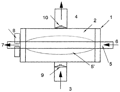
FIG. 2 shows a simple embodiment of a blood oxygenator designed according to
the
invention, which again is configured as a device 1 having an inner chamber 2
comprising a blood inlet 3 and a blood outlet 4. An elastically deformable and
at the
same time mass and/or energy-permeable hollow fiber 5 extends through the
chamber 2 transversely to the flow direction of the blood, wherein oxygen
flows
through the hollow fiber 5, in this example in the application of a blood
oxygenator,
namely from the gas inlet 6 on the right to the gas outlet 7 on the left.
To this end, the oxygen is fed continuously through the gas inlet on the
right, and the
CA 02679428 2009-08-28
11
pressure acting in the hollow fiber 5 is controlled by a pressure controller
8, which is
disposed in the region of the gas outlet and can be configured, for example,
such that
the effective cross-section of the hollow fiber 5 can be reduced or expanded.
If the cross-section here is reduced by the pressure controller 8, the
pressure in the
hollow fiber 5 increases such that it inflates and takes up a larger volume,
whereby in
the region 5', which is defined by the surface of the inflated hollow fiber 5,
blood is
displaced from the chamber 2. In order to implement a defined flow direction,
which is
to say from blood inlet 3 to blood outlet 4, it is provided to install an
inlet valve 9 at
the blood inlet 3 and an outlet valve 10 at the blood outlet 4, with both
valves
operating as one-way valves in the same direction.
In this way, it is ensured that upon a displacement, which is to say an
inflation of the
elastically deformable hollow fiber 5, blood is pushed out of the chamber 2
only
through the blood outlet 4, and upon a reduction of the volume of the fiber 5
the
resulting negative pressure and the closed outlet valve 10 cause new blood to
be
treated to be suctioned into the chamber 2 through the blood inlet 3 and the
inlet
valve 9.
In this embodiment according to FIG. 2, it is apparent that the elastically
deformable
fiber 5 not only implements the pump function inside the device 1, but due to
the fact
that this fiber at the same time is mass and/or energy-permeable that also the
mass
transfer, which is to say the gas exchange in this example, can take place
between
the blood and the gas phase.
In contrast, FIG. 3 shows another preferred embodiment of a blood oxygenator
as a
total device 1, in which both the above-mentioned chamber 2 and also another
chamber 11 are disposed. The design here is substantially comparable to that
from
FIG. 2, however a central elastically deformable hollow fiber 12, which is
used to
implement the pump function, but is not used for the mass transfer, extends
through
the chamber 2 and the chamber 11.
To this end, the chamber 11 serves the supply of the second medium in the
spirit of
the invention, which is to say for an application as a blood oxygenator for
the supply
of oxygen, which then is distributed to a plurality of mass-permeable hollow
fibers 5,
which extend substantially transversely to the blood flow through the chamber
2.
CA 02679428 2009-08-28
12
Here too, blood is pumped through a blood inlet 3 into the chamber 2 and out
of the
chamber 2 through the blood outlet 4, wherein again valves 9, 10 are used to
define
the flow direction. The key difference compared to FIG. 2 here, in addition to
the high
number of mass-permeable hollow fibers 5, which are disposed around the
central,
elastically deformable hollow fiber 12, is the additional characteristic
according to the
invention that the hollow fiber 12 has an elastically deformable region also
in the
chamber 11, so that upon a pressure increase inside the hollow fiber 12 blood
is
displaced not only in the chamber 2, but a pressure increase also takes place
in the
chamber 11, which continues to the individual mass-permeable hollow fibers 5.
In addition to the pump effect in the chamber 2 due to periodic pressure
fluctuations
in the hollow fiber 12, also a period pressure fluctuation in the chamber 11
is
obtained, and on the inside of the mass-permeable hollow fibers 5, such that
in
addition the gas boundary layer on the inside of the hollow fibers 5 is
disturbed.
The relationships present during a mass transfer in a blood oxygenator of the
above-
described kind are illustrated in more detail in FIG. 4, for example. In FIG.
4 a
membrane 5 is apparent, which can be provided, for example, by the wall of a
mass-
permeable hollow fiber 5 of the above-mentioned exemplary embodiment. From
inside the hollow fiber, the gas phase acts due to an increased oxygen partial
pressure p02. Directly abutting the membrane 5 is a gas boundary layer 13, in
which
the gas exchange takes place, so that the CO2 taken up from the blood is
enriched at
this boundary layer. Due to this enrichment, the effectiveness of the gas
exchange,
which is to say the transfer of oxygen into the blood, is reduced.
The embodiment according to FIG. 3, with the pulsation generated in the
chamber
11, brings about a destruction of this gas boundary layer 13, so that oxygen
can
reach the boundary regions of the membrane 5 more easily, thereby increasing
the
effectiveness of the overall gas exchange.
Similarly, the pump function generated internally in the chamber 2 causes
periodic
pressure fluctuations inside the chamber 2, by which a plasma edge 14 formed
on
the blood side on the membrane 5 with blood oxygenators is disturbed. Due to
this
disturbance of the plasma edge 14, the effectiveness of the mass transfer can
likewise be increased. The diagram of the oxygen partial pressure shows that
the
CA 02679428 2009-08-28
13
primarily relevant oxygen transfer takes place inside the plasma edge, which
is to say
here the oxygen partial pressure drops off significantly from the gas phase on
the
right to the blood phase on the left. Precisely the disturbance of the plasma
edge by
the pressure fluctuations occurring in the chamber 2, which are generated by
the
deformation of the elastic membrane, can therefore contribute significantly to
increasing the efficiency of the transfer rates.
FIG. 5 furthermore shows a possible embodiment of an elastically deformable
hollow
fiber 12. The elastically deformable fiber 12 shown here has a thick wall
region 14
and in part also a wall region 15, the thickness of which is reduced, so that
in the
case of a pressure increase on the inside of this hollow fiber 12 a bulging 16
will
develop substantially where the thickness reduction 15 is provided. This is
where the
hollow fiber 12 has been weakened the most, so that this wall region 15 will
give way
fastest under the pressure increase. With this embodiment it is thus possible
to
achieve a deformation of an elastic hollow fiber 12 in only one desired region
through
the arrangement of defined wall reductions, whereby, for example, also the
maximum
achievable volume change of the hollow fiber 12 can be defined.
FIG. 6 shows an example of the housing of a device according to the invention.
On
the left, a cross-sectional view of the chamber 2 through which the blood
flows is
apparent, having a substantially hexagonal cross-section. The rigid mass-
permeable
hollow fibers, which are not shown, are disposed perpendicular to the sheet
plane
and thus extend transversely to the flow direction of the blood, which flows
from the
blood inlet 3 to the blood outlet 4.
Centrally on the inside of the chamber, a cylindrical region 17 of permeable
hollow
fibers has been spared, and a deformable elastic hollow fiber 12 is disposed
centrally
therein in order to implement the pump function. In the illustration on the
right, the
connections 18 are shown for pressurizing the hollow fibers with a medium. The
oxygen connections are not shown here.
Overall, when looking at the invention, it is apparent that compact
oxygenators can
be implemented, which can be provided both for use in babies, particularly
premature
babies, and as implantable organs.
With respect to all embodiments, it should be noted here that the technical
features
CA 02679428 2009-08-28
14
mentioned in connection with an embodiment can be used not only with that
specific
embodiment, but also with the respectively other embodiments, which are
mentioned
or also not mentioned within the scope of this description. All technical
features
disclosed in this description of the invention shall be considered key
elements of the
invention and can be arbitrarily combined with each other, or used alone.