Note: Descriptions are shown in the official language in which they were submitted.
CA 02679966 2009-09-03
WO 2008/109748 PCTIUS2008/056052
Conveyor with Attachments
Field of the Invention
[0001] The present invention relates to interlocking-link conveyor belts and
has
particular application for belts that require specialized handling.
Background of the Invention
[0002] Interlocking link belts are used in a variety of applications. In some
applications, a material being conveyed requires special handling. For
instance,
in some applications it is desirable to minimize the contact between the belt
and
the material being handled. It can become cost prohibitive to design a
different
link belt for each different application. Accordingly, it is desirable to
develop a
link belt system that can be readily modified to address the varying
requirements
of different applications.
Summary of the Invention
[0003] In light of the foregoing, the present invention provides an
interlocking
link belt having one or more attachments that interlock with the links. The
attachments can be readily attached or detached from the -ink belt.
Additionally,
the attachments can be configured to address a variety of differing
circumstances.
Brief Description of the Drawings
[0004] The foregoing summary and the following detailed description of the
preferred embodiments of the present invention will be best understood when
read in conjunction with the appended drawings, in which:
-1-
CA 02679966 2009-09-03
WO 2008/109748 PCT/US2008/056052
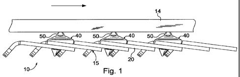
[0005] Figure 1 is a conveyor assembly conveying a workpiece;
[0006] Figure 2 is a perspective view of a portion of the conveyor assembly
illustrated in Figure 1;
[0007] Figure 3 is an enlarged plan view of a link of link belt in the
conveyor
assembly illustrated in Figure 1;
[0008] Figure 4 is a front side view of the link illustrated in Figure 3;
[0009] Figure 5 is an enlarged front side view of an attachment element of the
conveyor assembly illustrated in Figure 1;
[0010] Figure 6 is a right side view of the attachment element illustrated in
Figure 5;
[0011] Figure 7 is a plan view of the attachment element illustrated in Figure
6;
[0012] Figure 8 is a bottom view of the attachment element illustrated in
Figure
7;
[0013] Figure 9 is a side elevational view of a portion of an alternate
conveyor
assembly; and
[0014] Figure 10 is a plan view of the conveyor assembly illustrated in Figure
9.
Detailed Description of the Invention
[0015] Referring now to the figures, wherein like elements are numbered alike
throughout, a conveyor system is designated generally 10. The conveyor
system 10 comprises an interlocking link belt 15 and a plurality of
interlocking
attachments 40. The assembly 10 is shown transporting a workpiece 14.
[0016] The belt 15 comprises a series of interlocking belt links 20. Connected
to the belt, the attachments 40 provide minimal contact points between the
belt
15 and the workpiece 14.
-2-
CA 02679966 2009-09-03
WO 2008/109748 PCT/US2008/056052
[0017] One of the individual links that comprise belt 15 is illustrated in
Figures 3
and 4. Each belt link 20 has a body portion 22 and a fastener 30 connected to
the body portion. In the present instance, the thickness of the belt link 20
between the top surface 38 and the bottom surface 39 is substantially uniform
throughout the entire link.
[0018] The body portion 22 is generally rectangular, having two edges
extending longitudinally between a trailing end 23 and a leading end 24, both
of
which extend transversely between the two edges. Adjacent leading end 24 a
leading aperture 29 extends through the thickness of body portion 22.
Longitudinally spaced from the leading aperture 29 adjacent the trailing end
23,
a trailing aperture 28 extends through the thickness of body portion 22.
[0019] The leading end 24 corresponds to the direction in which the assembly
travels as shown by the arrow in Figure 1. However, the direction in which
the assembly 10 travels can be reversed so that the leading end 24 does not
lead the trailing end 23 with respect to the actual travel of the assembly.
[0020] The fastener 30 integrally connects the body portion 22, and comprises
a
fastening tab 32 and a constricted neck 33. The neck extends longitudinally,
with one end connected to the fastening tab 32, and the other end connected to
the leading end 23 of body 22. The length of the neck 33 between the trailing
end 23 and the fastening tab 32 is sufficiently long to allow the fastening
tab 32
to extend through the apertures in two or three belt links 20 depending on the
application.
[0021] The fastening tab 32 is generally trapezoidal shaped, having two
parallel
ends that are transverse the neck 33. The fastening tab 32 is substantially
wider
than the neck 33, being widest at the point where it intersects the neck, and
-3-
CA 02679966 2009-09-03
WO 2008/109748 PCT/US2008/056052
tapering as it extends away from the neck.
[0022] The belt links 20 are connected by passing the link fasteners through
the
apertures in adjacent belt links. To ensure that the belt links 20 can
properly
connect, the apertures are configured and dimensioned with reference to the
fastening tab and the neck.
[0023] In the present instance, the apertures through body 22 are non-
circular.
Both apertures 28 and 29 are longitudinally elongated so that their length 26
is
greater than their width. To ensure that fastening tab 32 can pass through the
apertures, the length of the apertures is greater than the greatest width of
the
fastening tab 32.
[0024] The width of apertures 28 and 29 is not constant. Instead, the
apertures
widen as they extend toward trailing end 24. To provide proper connection
between the belt links 20, the apertures are narrower than the fastening tab
width so that the fastening tab 32 cannot pass back through the apertures once
the belt links are connected. However, the apertures are wider than the neck
33
to allow the neck to extend through the apertures while the belt links are
connected, as will be discussed below.
[0025] The belt links 20 are made of a material of sufficient tensile strength
to
convey the weight of the workpiece 14. In the present instance, the belt links
20
are made of a urethane elastomer that is reinforced with a polyester fabric.
[0026] Referring now to Figs. 5-8, the details of the attachment elements 40
will
be described in greater detail. The attachment element 40 comprises a body
portion 45, an engagement portion 50 and a connector 55 for connecting the
attachment element to the link belt 15. In the present instance, the
attachment
-4-
CA 02679966 2009-09-03
WO 2008/109748 PCT/US2008/056052
elements are molded elements, formed of a thermoplastic or thermoset
elastomer. However, the attachments elements may be formed from a variety of
materials, including ceramic, metal, rubber or plastic materials depending on
the
application.
[0027] The body portion 45 comprises a generally wedge-shaped body that
tapers from the trailing edge 46 to the forward edge. In this way, the body
has a
thicker edge at the leading edge than at the trailing edge. The top surface 47
of
the body forms a pyramidal surface.
[0028] The engagement surface 50 projects upwardly from the top of the upper
surface 47. The engagement surface 50 may be formed in a variety of shapes
depending on the application for the belt 10. In the present instance, the
engagement surface 50 is a rounded protuberance. More specifically, the
engagement surface is a semi-spherical surface.
[0029] The bottom surface of the body 45 is generally planar. A notch or
pocket
49 is formed in the bottom surface of the body, adjacent the leading edge of
the
body. The pocket 49 is configured to accommodate a portion of the neck 33 of
one of the belt links. Specifically, the pocket has a width that is at least
as wide
as the width of the neck 33 of a belt link, and the pocket has a depth that is
at
least as great as the thickness of the neck. In this way, as described below
more fully, the bottom surface of the attachment element 40 lies flush against
the top surface of a link 20 of the belt, without interfering with the neck 33
of an
adjacent belt link.
[0030] The connector 55 is a barbed connector that projects downwardly from
the bottom surface of the body 45. The connector 55 is configured to connect
the attachment element 40 to the belt after the belt links are assembled. The
-5-
CA 02679966 2009-09-03
WO 2008/109748 PCT/US2008/056052
connector comprises a neck 57 and a barb 59 that flares outwardly from the
bottom end of the neck. The neck 57 is configured to fit into the apertures of
the
belt links 20 after the belt links are assembled. Specifically, the upper edge
of
the barb forms a shoulder configured to confront the bottom surface of the
belt.
The neck 57 of the connector is elongated so that the length of the neck is at
least twice the thickness of the belt links. Additionally, in the present
instance,
the neck 57 has a central axis that is not aligned with a central axis of the
engagement surface 50.
[0031] To form a conveyor system 10, a plurality of belt links 20 are
connected
together to form a link belt 15. More specifically, the belts are connected in
successive overlapping relation by inserting the fasteners 30 of preceding
links
through the apertures 28, 29 of successive links. As shown in Fig. 1, the
fastener 30 of each link extends through apertures in two successive links in
the
present embodiment.
[0032] The attachment elements 40 are connected with the belt 15 after the
links are assembled to create the belt. To connect an attachment element 40,
in
the present embodiment, the connector 55 for the attachment element is
displaced through a pair of aligned apertures in the belt links similar to the
way
in which the belt link fasteners extend through the aligned apertures to
connect
the belt links together. The connector 55 extends through the aligned
apertures
so that the barb 59 projects from the bottom of the belt, with the top surface
of
the barb confronting the bottom surface of the belt. The body 45 of the
attachment element overlies the top surface of one of the links 20 of the
belt.
The body of the attachment element 45 is wider than the apertures 28, 29 of
the
belt links 20, and in the present instance, the body 45 is approximately as
wide
as the belt 15. Additionally, in the present instance, the attachment element
40
overlies the rearward half of the body 22 of a belt link, including the
trailing
-6-
CA 02679966 2009-09-03
WO 2008/109748 PCT/US2008/056052
aperture 28 of the link. The neck 33 of the adjacent preceding link projects
into
the pocket 49 formed in the bottom of the attachment element.
[0033] In this way, as shown in Figs. 1-2, the attachment element 40 overlies
the belt link without any significant gap between the top surface of the belt
and
the bottom surface of the attachment element. Therefore, the attachment
element forms a cover over the forward half of one of the belt links,
preventing
contaminants from becoming lodged in the aperture, which could cause damage
to the belt or the workpiece 14. Additionally, the configuration of the upper
surface 47 of the attachment element 40 tends to deflect contaminants away
from the engagement surface 50. Specifically, the tapered surfaces of the
upper
surface taper downwardly and away from the engagement surface 50. The
tapered surfaces deflect contaminants away from the engagement surface 50,
thereby reducing the likelihood that contaminants, such as pieces from the
work
piece or other items, will lodge between the belt and the workpiece, causing
damage to the workpiece or the belt.
[0034] Additionally, as discussed above, the attachment element 40 overlies a
substantial portion of one of the belt links 20 of the belt 15. Since the
bottom
surface of the attachment element is generally planar, the body portion 47
operates as a stop limiting substantial lateral displacement of the attachment
element across the width of the belt. In other words, the engagement between
the bottom surface of the attachment element 40 and the top surface of the
belt
link operates to impede the attachment element from rocking relative to the
belt.
[0035] In some instances, it may be desirable to limit the contact between the
belt 15 and the workpiece 14. The attachment elements 40 may be connected
with the belt at a desired spacing to reduce the contact with the workpiece
14.
In the present instance, the attachment elements 40 are connected to every
-7-
CA 02679966 2009-09-03
WO 2008/109748 PCT/US2008/056052
other link, however, the attachment elements may be connected closer together,
such as on every link, or two elements every three links. Alternatively, the
elements could be connected further apart, such as every third or fourth link.
In
this way, the attachment elements 40 provide flexibility so that the user can
select the appropriate spacing of the contact points between the conveyor
system 10 and the workpiece, and then connect the attachment elements to the
belt 15 at the desired spacing.
[0036] As shown in Figs. 1-2, the engagement surfaces 50 of the attachment
elements are configured to maintain a substantially constant engagement
surface between the workpiece 14 and the conveyor system 10 in the event of
displacement of the belt 15 relative to the workpiece. Specifically, in the
present
instance, the engagement surface 50 is rounded so that if the attachment
element 40 rotates relative to the workpiece, the engagement surface
contacting
the workpiece remains substantially the same. Accordingly, in the present
instance, the configuration of the engagement surface 50 minimizes or
eliminates stress concentrations that may arise between the conveyor 10 and
the workpiece 14 when the attachment elements rotate relative to the
workpiece.
[0037] Referring now to Figs. 9-10, an alternate embodiment of the conveyor
assembly is designated 110. In the alternate embodiment, the belt 15 and
attachment elements 40 are substantially similar to the belt and attachment
elements illustrated in Figs. 1-8 and described above. In the alternate
embodiment 110, a second type of attachment element 70 is also attached to
the belt. The second attachment elements 70 are flat elements.
[0038] The flat elements 70 have a body portion 75 and a barbed connector 80.
The barbed connector is configured substantially similar to the barbed
connector
55 described above. Additionally, the body portion 75 of the flat elements 70
is
-8-
CA 02679966 2009-09-03
WO 2008/109748 PCT/US2008/056052
similar to the body portion 45 described above. Specifically, the body portion
has a generally flat bottom surface having a recess configured to accommodate
the neck 33 of a preceding belt link. Additionally, the body portion 75 is a
wedge-shaped portion, tapering rearwardly from the leading edge, so that the
leading edge of the body is thicker than the trailing edge. In contrast to the
upper surface of the attachment elements 40 described above, the flat elements
70 have a substantially flat upper surface.
[0039] In the embodiment illustrated in Figs. 9-10, the flat elements 70 are
attached to the belt between the protruding attachment elements 40. In this
way, the engagement surfaces 50 of the attachment elements 40 protrude
above the upper surface of the flat elements 70 so that there is essentially
no
contact between the workpiece 14 and the flat elements. Specifically, the
workpiece spans adjacent engagement surfaces 50 without contacting the upper
surface of the flat elements 70. In this configuration, the flat elements
operate
as shields covering the top surface of the belt links between the belt links
to
which the attachment elements 40 are connected. Specifically, in the present
instance, the flat elements 70 are substantially coextensive with the exposed
portion of the body 22 of one of the links 20 in the belt. Therefore, the flat
element 70 overlies the exposed portion of the belt link 20 and also covers
the
exposed aperture 28. In this way, the flat element 70 prevents contaminants
from becoming lodged against the belt 15, particularly within the apertures in
the
belt, which could cause damage to the belt or the workpiece 14 during
operation.
[0040] Although the flat elements 70 have been described as having a flat
upper
surface, it may be desirable to configure the upper surface of the flat
elements
70 such that the elements have an angled upper surface such that the upper
surface tends to deflect contaminant materials away from the belt. However, in
-9-
CA 02679966 2009-09-03
WO 2008/109748 PCT/US2008/056052
such an embodiment, it is desirable to have the upper surface remain below the
height of the engagement surfaces 50 of the attachment elements 40.
Therefore, the workpiece will only contact the engagement surfaces 50 of the
attachment elements 40 rather than any of the elements attached to the belt
intermediate the attachment elements.
[0041] In addition to being attached to the belt as described above, the flat
elements 70 may be attached to the belt instead of the attachment elements 40
described above. In this way, the flat elements 70 may be attached to each
link
20 in the belt, or fewer links if desired. The wedge shaped bodies of the flat
elements 70 may be configured so that when the elements are attached to the
belt 15, the height of the leading edge of the element is substantially the
same
as the height of the trailing edge of the element connected to the preceding
link
of the belt. Configured in this manner, the flat elements may form a series of
elements having substantially aligned flat upper surfaces to create a
substantially flat profile for the belt.
[0042] In the foregoing description, elements are attached to a link belt 15
to
alter the exposed surface of the link belt. The first element described is the
attachment element 40, which included a protuberance for providing limited
contact surface between the link belt and the workpiece 14. The second type of
element described above is the flat element 70 for providing a cover or a
generally flat engagement surface, depending on the application. As these two
examples illustrate, the elements attached to the link belt can incorporate a
variety of configurations to accommodate various applications.
[0043] In addition to the two configuration described above, alternate designs
can be created having differently shaped upper surfaces. In one example,
rather than having a flat upper surface as in the flat elements 70, the upper
-10-
CA 02679966 2009-09-03
WO 2008/109748 PCT/US2008/056052
surface can be rounded or domed shape. The rounded shape may be formed
so that the rounded surface extends across substantially the entire width of
the
upper surface, rather than being a rounded protuberance as shown in the
attachment element 40 described above. Similarly, rather than being rounded,
the upper surface of the attachment elements may be configured to have a
reduced area contact surface, such as a pyramid shape or a plurality of small
protuberances.
[0044] In addition to providing different surface configurations, the
attachment
elements may provide different material handling characteristics. For
instance,
the upper surface of an attachment element may include a layer of cushioning
material attached to or formed in the body of the attachment element. One
example of a cushioning material is a layer of foam that would provide a layer
of
cushioning, conformability or additional grip. Similarly, a layer or envelope
of gel
could be added to the top surface to provide a cushioning layer. In this way,
the
lower portion of the attachment element, such as the fastener 30 and/or the
body portion 45 may be formed of one material, while a second material, such
as the foam, gel or other type of material forms the surface that engages the
work piece.
[0045] Other features that could be incorporated into the upper surface of the
attachment element include grit materials or other materials that would
increase
the coefficient of friction of the upper surface. Similarly, elements that
protect
the work piece could be incorporated into the upper surface. For instance,
flock
could be applied to the upper surface to provide a low friction and/or non-
marring contact surface between the belt and the workpiece.
[0046] Further still, rotatable elements can be incorporated into the
attachment
elements. For example, a roller or wheel can be mounted onto an axle so that
-11-
CA 02679966 2009-09-03
WO 2008/109748 PCT/US2008/056052
the roller is rotatable. The roller can be mounted so that the axle is
parallel or
normal to the direction of travel of the link belt 15. In this way, the roller
can
rotate in the same direction as the direction of travel for the belt, or the
roller can
rotate at an angle (such as normal) to the direction of travel of the belt. In
this
way, a workpiece can be readily conveyed across the belt, at an angle to the
direction of travel of the belt. Similarly, a rotatable ball can be mounted to
the
top surface of the attachment elements. For instance, a ball, such as a ball
bearing, can be mounted in a socket formed on the upper surface of the
attachment element. In this way, the ball would be rotatable relative to the
work
piece to allow the work piece to be easily repositioned relative to the top
surface
of the conveyor assembly.
[0047] Another type of material handling element that may be incorporated into
the attachment elements is an elongated finger or rib that may protrude from
the
upper surface of the attachment elements. For instance, one or more elongated
fingers may extend upwardly from the surface of a link configured similarly to
the
flat elements 70. The fingers may be deformable to form a surface like a
brush,
or a cushioning or spring-like effect.
[0048] It will be recognized by those skilled in the art that changes or
modifications may be made to the above-described embodiments without
departing from the broad inventive concepts of the invention. It should
therefore
be understood that this invention is not limited to the particular embodiments
described herein, but is intended to include all changes and modifications
that
are within the scope and spirit of the invention as set forth in the claims.
-12-