Note: Descriptions are shown in the official language in which they were submitted.
CA 02680308 2014-05-14
54106-330
11
Stator arrangement, generator, wind turbine, and method for
positioning a stator arrangement
FIELD OF INVENTION
The invention relates to a stator arrangement of an electric
machine, especially of a generator for a wind turbine. The
=
invention concerns also a generator, e.g. a direct drive
generator for a wind turbine comprising such a stator
arrangement as well as a wind turbine comprising such a
generator. Furthermore the invention relates to a method for
positioning a stator arrangement.
BACKGROUND
Each wind turbine comprises a generator, e.g. a large direct
drive generator having a generator stator and a generator
rotor for the production of electrical energy.
Wind turbines are erected onshore as well as offshore. In
particular, when a wind turbine is erected offshore, the wind
turbine as a whole, but also the generator is exposed to
rough environmental conditions, like humidity, salty
particles, etc. If not sufficiently protected in particular
the stator components of a wind turbine generator are exposed
to damages due to corrosion and to an increased risk of
electrical faults under such offshore environmental condi-
tions. Besides, other reasons might be present so that a
fault might occur, offshore or onshore.
Obviously a failure of the generator should be avoided, but
in case of a failure a quick and easy maintenance and repair
of the failure should be made possible.
It is advantageous when the generator stator comprises a
series of independent stator segments. A segmented stator has
the benefit that in case of a fault the respective affected
stator segment can be replaced at a fraction of the costs and
effort required for the replacement of the complete stator.
CA 02680308 2014-05-14
54106=330
=
2
However, during the transportation and the handling of the.
=
individual stator segments, e.g. in the course of the
erection of the wind turbine, the stator segments may be
exposed to humid and salty ambient conditions which may cause
=
a damage of single stator segments.
It has to be acknowledged that a generator may be comprised
of rotor elements, e.g. permanent magnets, and stator
elements, e.g. a laminate stack with windings. Such genera-
tors, in particular generators of a wind turbine, may be of
large size, like direct drive or directly driven generators
with possibly a diameter of several metres. In such a
generator, in the case of a failure of a stator segment, it
might be difficult to exchange a stator segment due to the
size and weight, especially if not the whole generator should
be replaced as one. For the repair of a generator or the
= exchange of generator parts an access opening might be
= available but still it might be difficult to reach or to
exchange the defect part via that opening.
Especially a difficulty arises in configurations with direct
drive generators where the generator is placed between the
hub and the tower in order to yield a compact machine
construction. Such a construction can be seen in Figure 2.
. 25 Here it will usually be necessary to dismantle the whole hub
=
to eventually dismantle the stator of the generator.
SUMMARY
It is therefore an object of some embodiments of the present invention
to provide a stator arrangement, a generator, a wind turbine as well as
a method as initially mentioned in such a way that a
replacement of stator parts can performed in a simpler way.
CA 02680308 2014-05-14
54106.-330
3
The stator arrangement of an electric machine described herein is
directed to an inner stator and an outer rotor. The electric
machine may be especially a generator for a wind turbine.
Specifically some embodiments of the invention concern the stator
arrangement of an electric machine, wherein the stator arrangement is
radially surrounded by a rotatably mounted rotor arrangement.
During normal operation - the intended use of the generator
during operator of the electric machine - the stator
arrangement is non-rotatably connected to a stationary part
of the generator. The stator arrangement is releasable from
the non-rotatable connection to the stationary part of the
generator so as to be revolved relative to the stationary
part of the generator.
Thus, the stator arrangement is interlocked with a stationary
part of the electric machine in such a way that the stator
arrangement remains fixed to the stationary part during
normal conditions, but where the stator arrangement can be
made to rotate around the stationary part in case of
replacement of parts of the stator, e.g. during maintenance
or during non-normal operation of the generator during which
the generator is not under load.
Particularly the stator arrangement may be interlocked with a
rotating part of the electric machine causing the stator
arrangement to revolve uniformly with the rotating part if
the rotating part rotates, particularly the stator arrange-
ment and the rotor arrangement having the same angular speed.
The stator arrangement may be set up around a concentric
shaft and the rotor arrangement may be supported on the
shaft.
CA 02680308 2014-05-14
54106-330
4
The stator arrangement according to some embodiments of the invention is
particularly advantageous if maintenance or repair of a
=
stator segment is necessary and an access opening in the
casing of the electric machine to the stator arrangement is
available but from the access opening only a fraction of
stator segments can be reached. Some embodiments of the invention
allow to reposition the stator in a maintenance step via a revolving
turn of the complete stator arrangement around its axis of
rotation so that the stator segment that needs to be replaced
will be reachable by service personnel or by service
equipment via that access opening.
Possibly removable fixation like bolts may be used to lock
the stator in an unrevolvable position during normal
operation of the electric machine. This fixation, namely the
bolts, may then be removed to be able to revolve the stator
arrangement around its axis of rotational symmetry.
Some embodiments of the invention are especially advantageous for very
large electric machines like generators for power generation. Due
to the heaviness of the generators a single stator segment
might be heavy and difficult to handle when replaced. Some embodiments
of the invention simplify the exchange of a stator. segment. This
is especially true if the generator is mounted in a wind
turbine or another compact arrangement with little space to
operate.
The interlocking of the stator arrangement with a rotating
part of the electric machine may be performed in different
ways. In a first preferred embodiment the interlocking of the
stator arrangement with the rotating part can be performed by
mechanical locking of the stator arrangement with the
rotating part. Before this interlocking can take place, a
fixation of the stator arrangement that is used to keep the
stator arrangement unrevolvable during normal operation of
the electric machine, may be removed. Additionally the
revolving of the stator arrangement may be guided that way
CA 02680308 2009-09-23
= 200818785
that only rotating movements will be allowed by a flange used
as a guiding rail for the stator arrangement. Axial movements
parallel to the axis of symmetry of the rotor or stator will
be prohibited by the flange. Possibly the stator arrangement
5 will be comprised of end plates attached to the axial ends of
the cylindrical stator arrangement, the end plates being
formed to exactly match the flanges.
In a second preferred embodiment the interlocking of the
stator arrangement with the rotating part can be performed by
applying direct current to coils intended for electromagnetic
induction of the stator arrangement and/or the rotor
arrangement so that the stator arrangement is locked with the
rotating part - especially the rotor of the electric machine
- via electro-magnetic force. In a lot of cases the rotor
arrangement comprises permanent magnets and the stator
arrangement comprises coils around a metal body even though
an opposite configuration would be feasible, so that applying
current to the coils will lead to an electro-magnetic force
between the adjacent parts of the rotor and the stator.
As in the first embodiment, before this interlocking can take
place, a fixation of the stator arrangement that is used to
keep the stator arrangement unrevolvable during normal
operation of the electric machine, may be removed. Addition-
ally again it is assumed, that two end plates may be used for
fixation - e.g. via bolts - of the stator segments and that
the rotation of the end plates during maintenance may be
guided by flanges. Then the stator arrangement including its
stator segments and its joined end plates are revolvable as a
joined unit and may revolve altogether, attracted by the
rotating rotor via the electro-magnetic force, around its
axis of symmetry. Even though the stator and the rotor are
attracting each other due to the electro-magnetic force, the
end plates provide a support that no radial movement of the
stator or the stator segments are possible.
CA 02680308 2014-05-14
54106-330
6
In contrast to that in a third embodiment such a radial
movement of the stator or the stator segments is used as an
alternative for the previously mentioned solution. During
normal operation the stator arrangement may be comprised of
stator segments joined with two end plates, e.g. via bolts. For
maintenance, the stator arrangement may be disassembled by
dismantling the end plates and the stator segments, e.g. by
loosening the bolts. Before, direct current may be applied to
the coils of the stator so that electro-magnetic force is
exerted between the rotor and the stator. Also before the
disassembly, some kind of protective material like plates of
nylon or rubber may be inserted into the air gap between the
rotor and the stator so that the rotor and stator do not damage
themselves when attracted to each other. By applying the direct
current, each of the stator segments of the stator arrangement
may be locked separately to an opposing rotor section due to
the electro-magnetic force. Then the rotor can be rotated
causing also the stator segments to rotate, because they
revolve jointly with the opposing rotor section. The end plates
itself may not rotate at all. And once in the right position
the stator segments may be rebolted again to the end plates.
Afterward the current may be shut down.
All three mentioned embodiments above allow repositioning the
stator for maintenance or repair by revolving the stator, so
that a specific to be repaired stator segment may be adjusted
at a specific position so that an easy access to that stator
segment is possible for service personnel.
The object of some embodiments of the present invention may
also be achieved by a generator comprising a stator arrangement
CA 02680308 2014-05-14
54106-330
6a
as described before and a wind turbine comprising a generator
with a stator arrangement as described before. Besides, the
object of some embodiments of the present invention may also be
achieved by a method for positioning a stator arrangement.
According to one aspect of the present invention, there is
provide a stator arrangement of an electric machine set up in a
cylindrical form, wherein the stator arrangement is radially
surrounded by a rotatably mounted rotor arrangement, during
normal operation the stator arrangement is non-rotatably
connected to a stationary part of the electric machine, the
stator arrangement is releasable from the non-rotatable
connection to the stationary part of the generator so as to be
revolved relative to the stationary part of the generator, the
stator arrangement is interlocked with a rotating part of the
electric machine causing the stator arrangement to revolve when
the rotating part rotates, and the interlocking of the stator
arrangement with the rotating part is performed by applying
direct current to coils intended for electro-magnetic induction
of one of the stator arrangement and rotor arrangements so that
the stator arrangement is locked with the rotating part via
electro-magnetic force.
According to another aspect of the present invention, there is
provided a generator, comprising: a stator arrangement of an
electric machine set up in a cylindrical form as described
herein.
According to yet another aspect of the present invention, there
is provided a method for positioning a stator arrangement of an
electric machine set up in a cylindrical form, the stator
CA 02680308 2014-05-14
54106-330
6b
arrangement being radially surrounded by a rotatably mounted
rotor arrangement, comprising: interlocking the stator
arrangement with a stationary part of the electric machine so
that during normal conditions the stator arrangement is fixed
to the stationary part such that the stator arrangement is non-
rotatably connected to the stationary part; releasing the
interlocking and interlocking the stator arrangement with a
revolving part so that during non-normal conditions so that the
stator arrangement is rotatable around the stationary part, and
wherein the interlocking of the stator arrangement with the
rotating part comprises applying direct current to coils
intended for electro-magnetic induction of one of the stator
arrangement and rotor arrangements so that the stator
arrangement is locked with the rotating part via electro-
magnetic force.
= CA 02680308 2014-05-14
54106--330
7
BRIEF DESCRIPTION OF THE DRAWINGS
The invention will in the following be explained in more
detail with reference to the schematic drawings, wherein
FIG. 1 shows a wind turbine,
FIG. 2 shows modules of a wind turbine,
FIG. 3 shows a generator of a wind turbine within its
.housing,
FIG. 4 shows a drawing of a generator,
FIG. 5 shows a sectional drawing of a generator stator
mechanically fixable to the shaft of the generator,
FIG. 6 shows a three-dimensional drawing of a generator
.
with a stator electro-magnetically fixable to a ro-
tor of the generator;
DETAILED DESCRIPTION
FIG. 1 shows a wind turbine 1 comprising a tower 2, a nacelle
3 and a hub 4 with rotor blades 5. In the nacelle 3 several
= further components of the wind turbine 1 are arranged like a
generator 11 as it is schematically shown in FIG 2. The
generator 11 is in a not shown manner connected to the hub 4
for the production of electrical energy and has a substan-
tially horizontally aligned centre axis A.
FIG. 2 shows some basic components of a wind turbine 1. The
components are shown with a slight gap between each other,
even though when assembled, these gabs are closed. Again, a
hub 4 is shown to which the rotor blades - not shown - will
be attached. Further components, each adjacent to each other,
are the generator 11, the load/bearing section 12, which has
-
a connection to the not shown tower 2. Next, further
components are a control unit 13, cooling equipment 14, and
an end cap 15.
Whereas in FIG. 2 the generator 11 is set up in front of the
tower between the rotor blades and the tower, in FIG. 3, in
which an alternative wind turbine is shown inside its
housing, the generator 11 is arranged behind the tower.
Specifically you can see in FIG. 3 that the generator 11
CA 02680308 2014-05-14
54106-330
8
attached to a shaft 16. In such a design and with an inner
stator of the generator 11 that is radially surrounded by a
rotor of the generator 11, maintenance of stator components
of the generator 11 may be difficult and may only be possible
via axial manholes (not shown in FIG. 3).
FIG. 4 shows a drawing of a generator 11 - FIG. 4A as three-
dimensional drawing and FIG. 4B as cross sectional drawing.
Mainly only the cylindrical housing of the generator 11 can
be seen, comprising a generator end plate 60. The axis of
symmetry of the generator 11 is indicated by the line A. The
generator end plate 60 comprises an exemplary manhole 61
which allows access to inner parts of the generator 11.
Indicated by dashed or dotted lines, are also inner parts of
the generator 11, like the outer rotor 62 and the stator 64,
the stator 64 comprising stator segments (not shown) and a
stator end plate 63, which optionally may also have some cut-
outs 65 for maintenance or to reduce weight.
The stator end plate 63 may be permanently fixated to the
stator segments, but may be detachable, e.g. by using bolts
=
66 that may be removed for maintenance. In FIG. 4B also the
shaft 16 of the wind turbine is indicated around the axis of
symmetry A.
The manhole 61 as a cut-out in the generator end plate 60
ensures the possibility of going through the generator end
plate 60 for maintenance. Even though the manhole 61 is
limited to a section of the generator end plate 60, the
approach to adjust a defect stator segment right
that way that it can be reached via the manhole 61 allows an
easy maintenance, repair, or replacement of defect stator
parts. Also several manholes may be possible.
Basis for all embodiments that will be discussed in the
following is that a generator 11 comprises an inner stator
that is radially surrounded by an outer rotor. "Inner" and
CA 02680308 2014-05-14
54106-330
9
"outer" relate to a position in respect of a rotation axis A
.
of the cylindrical generator 11. "Inner" means closer to the
axis A, "outer" means further away from the axis A.
. . .
In some drawings the outer rotor will not be shown but one
has to be aware that the outer rotor will be present in the
generator 11 and it is an object of some embodiments of the invention
that the rotor will not be removed for maintenance.
Besides, it will be assumed that one of the stator arrange-
ment and rotor arrangement providing magnets for magnetic
forces and the other one of the stator arrangement and rotor
arrangement comprising coils. Specifically in the following
embodiments it will be assumed that the inner stator will be
comprised of coils embedded in laminated sheets of metal. The
magnets will be comprised in the circumferential outer rotor.
Furthermore it is assumed that a narrow air gap will be
present between the outer circumferential radial surface of
the stator and the inner radial surface of the rotor.
In FIG. 5 a generator 11 is shown as a sectional drawing,
= showing a section through the central axis A of the generator
11. The drawing is very schematic and simplified.
In the figure centrally located
around the axis A of rotation, is a revolving part 16A of a
shaft 16. This revolving part 16A of the shaft 16 is
connected to the hub - not shown in FIG. 5; see hub 4 in
FIG. 2. - and to the rotor, which is not shown, which all
revolve around the axis A.
Around the revolving part 16A of the shaft 16 there will be -
possibly coupled via bearings 20 - a fixed, non-revolving
part 16B of the shaft 16.
During normal operation of the generator 11, stator segments
50 - in the cross section only one stator segment is
=
indicated - are interconnected with two end plates 18, which .
CA 02680308 2009-09-23
200818785
again are interconnected with the non-revolving part 16B of
the shaft 16. The end plates 18 correspond to the stator end
plates 63 according to FIG. 4. The interconnection between
the stator segment 50 and the end plates 18 are schematically
5 shown in the figure simply by a contact surface between the
outer radial surface of the end plates 18 and an inner radial
surface of the stator segment 50. Any kind of separable or
inseparable link is possible, because for the process
explained with FIG. 5, the stator segments 50 will continu-
10 ously be kept assembled with the end plates 18. The intercon-
nection between the end plates 18 and the non-revolving part
163 of the shaft 16 will be arranged as separable link, e.g.
via bolts 40. In the cross section of FIG. 5 only two bolts
40 are shown, but a number of bolts may be present throughout
the circumference of the non-revolving part 16B of the shaft
16.
In FIG. 5 the non-revolving part 16B of the shaft 16 will
have two circumferential flanges 41 - in FIG. 5 shown with a
gap indicating a tubular recess for inserting the bolt 40 -
allowing the end plates 18 to connect to the flanges 41 via
the bolts 40. For this each of the end plates 18 may be
formed correspondingly to one of the flanges 41, quite
perfectly fitting to the flanges 41 by having the correspond-
ing cross sectional form. The radial inner part of the end
plates 18, next to the flanges 41 and surrounding them, may
have holes so that the bolts 40 can be inserted through the
holes of the end plates 18 and through the tubular recess of
the flanges 41 to physically connect these two parts. During
normal operation of the generator 11, the bolts 40 will be
inserted and the stator will not be revolving. This is the
intended work mode of the generator.
The flanges 41 may be rotational symmetric without any
potrusions at the outer radial surface of the flanges 41, so
that the stator 11 including the stator segments 50 the end
plates 18 may be guided by the flanges 41, so that, if
CA 02680308 2014-05-14
54106-330
11
unbolted and not locked to the flanges 41, essentially no
axial movement of the stator 11 is possible only allowing
revolution of the stator 11 around the axis A.
In the figure the flanges 41 are in form of an annulus with
essentially rectangular cross section. In this case the end
,
plates 18 will be formed at their radially inner end as a U-
shaped circumferential pit. The cross-sectional U-shape
should essentially perfectly match the cross-sectional form
of the flanges 41, so that the U-shape will also be comprised
of essentially right-angled sides.
Not shown in FIG. 5, there is a possibility to temporarily
physically connect the stator to a revolving part of the
generator, e.g. the revolving part 16A of the shaft 16 or a
part of the outer rotor.
In case of a failure, the need to repair or the need to
replace a stator segment 50, the generator 11 might stop
revolving automatically or by manual intervention. Service
personnel may identify a defect in a stator segment 50 and
may realize that a repair or exchange of that stator segment
50 may not be possible, because the manhole 61 in the
generator end plate 60 and the to be exchanged stator segment
50 may not be aligned properly so that an exchange via the
manhole 61 is not directly possible. Now the idea
comes into place, so that the stator will be revolved by such
an angle so that the to be exchanged stator segment 50 will
be aligned in relation to the manhole 61, so that the
respective stator segment can be accesses through the manhole
61.
To revolve the stator, the bolts 40 connecting the end plates
18 with the non-revolving part 16B of the shaft 16 will be
35 removed overall the circumference. The stator with all its ' =
stator segments 50 now may be "loose" in respect of revolving
movements guided by the flanges 41. The flanges 41 will also
CA 02680308 2009-09-23
200818785
12
prohibit axial movements of the stator segments 50. The next
step would be to interlock the stator segments 50 with a
rotating part of the generator 11 causing the stator
arrangement with its stator segments 50 to revolve if the
rotating part rotates. This can take place by mechanically
locking the stator segments 50 with the revolving part 16A of
the shaft 16 or with the rotor.
Revolving this interlocked rotor-stator entity may take place
by applying a revolving force to the revolving part 16A of
the shaft 16. One possibility would be to have a motor that
could be temporarily connected to the generator 11, specifi-
cally to the revolving part 16A of the shaft 16 or to the
rotor. Without an additional motor, the interlocked rotor-
stator entity could be driven by the wind blades 5 of the
wind turbine 1. The wind blades 5 may be in idling position
to guarantee a very slow rotation. To guarantee that the
revolving will be very slow, maybe additional brakes may be
applied while revolving or the wind blades 5 may be tilted
that way that only a slight driving force will act upon the
wind blades 5 and consequently to the hub 4 and to the
revolving part 16A of the shaft 16. Possibly also a gear may
be present to reduce the revolving speed so that a very
precise rotation may be possible of the interlocked rotor-
stator entity without causing further negative effects, e.g.
damage, on the rotor or the stator.
Once properly adjusted, the rotation of the revolving part
16A of the shaft 16 will be discontinued. A precise alignment
of holes in the stator end plates 18 with its holes for the
bolts 40 and the flanges 41 may be necessary so that
rebolting them may be possible. Then, the bolts 40 may be
inserted again to fix the stator arrangement to the flanges
and consequently to the non-revolving part 16B of the
35 shaft 16. Then the temporary fixation of the stator segments
to the rotor or the rotating part 16A of the shaft will be
removed again.
CA 02680308 2009-09-23
200818785
13
Being in this position, finally the defect stator segment 50
may be removed or be repaired easily via the manhole 61. For
this the rotor may be locked manually by pin or some other
means so that no moving parts may harm the service personnel.
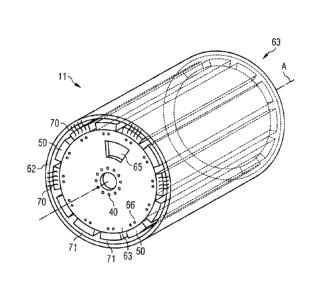
Proceeding to FIG. 6 two alternatives will be discussed to
allow a rotation of the stator arrangement and to provide
interlocking of the stator arrangement to a revolving part of
the generator. In these alternatives, the interlocking is
performed by locking the stator segments via electro-magnetic
force to the rotor, specifically its permanent magnets.
It will be utilised that coils and magnets for generation of
three-phase current will be present in the generator. But
instead of the induction of current into the coils due to the
rotation of the rotor - which is the normal operation of a
generator -, actively direct current is applied to all or
some of the coils in that way, that the stator coils will be
attracted by the opposing permanent magnets of the rotor. In
view of the fact that the air gap between the rotor and the
stator may be small, the magnets may be "strong" and a lot of
coils will be present, it may be possible to attract the
stator with such a force, that, if the stator would not be
bolted to the non-revolving part 16B of the shaft 16, the
stator would revolve with the same speed as the rotor. Thus
the rotor and the stator would be interlocked both as one
united revolving unit.
This effect will be utilised by the present embodiment of the
invention, so that like in the previous embodiment the stator
arrangement will be loosened from the non-revolving part 16B
of the shaft 16 but the fixation to the rotating part 16A
will not be performed by mechanically locking the stator to
the rotating part but only by applying direct current to the
coils, so that the stator segments 50 are attracted via
electro-magnetic force - indicated in Fig. 6 by a plurality
CA 02680308 2009-09-23
200818785
14
of oscillating lines with reference sign 70 - to the rotor 62
and an interlocking with the rotor 62 takes place.
Then, as before, the rotor 62 may be rotated by applying a
revolving force to the revolving part 16A of the shaft 16.
This will not be discussed further because this does not
differ from the previously discussed embodiment. Finally,
once in the proper position, the rotation may be stopped, the
stator arrangement may be mechanically locked again to the
non-revolving part 16B of the shaft 16, and the direct
current will discontinued, thus ending the electro-magnetic
force 70. Then the maintenance work can be executed.
For this embodiment it needs to be acknowledged, that the
stator arrangement including all its stator segments 50 and
its stator end plates 63 physically stays as one entity and
will not be disassembled for revolving the stator. The same
is true for the first embodiment according to FIG. 5.
A further embodiment will also be explained by means of FIG.
6. In this embodiment the stator will be disassembled before
revolving the disassembled stator segments 50. Even though
the stator will be disassembled all stator segments 50 will
stay in their relative positions which will again be forced
by applying direct current and by utilising electro-magnetic
force 70. This will be explained in the following.
Starting situation may be again that the stator segments 50
are attached to end plates 63, the end plates 63 attached to
the non-revolving part 16B of the shaft 16 via bolts 40. Now,
some kind of protective sheet will be inserted into the air
gap 71 between rotor 62 and stator segments 50. The end
plates 63 may stay attached with the non-revolving part 16B
of the shaft 16 and direct current will be applied to the
stator coils of the stator segments 50. Now, once the stator
segments 50 will be attracted to the rotor 62, fixation of
the stator segments 50 to the stator end plates 63 may be
CA 02680308 2009-09-23
200818785
manually be removed, e.g. by removing the bolts 66. Now every
stator segment 50 may itself be attracted to the rotor 62.
Once the shaft and/or the rotor 62 get revolved driven by the
wind blades 5 or by an extra motor, the rotor 62 rotates
5 together with the detached plurality of stator segments 50 as
one unity, but without the stator end plates 63 of the stator
arrangement. Finally, when a proper position is reached, the
single stator segments 50 will be reattached to the end
plates 63 by inserting the bolts 66 again. When finished, the
10 current may be switched off to discontinue the electro-
magnetic force 70.
The last embodiment differs from the previous ones, that a
cut-out 65 within the stator end plates 63 may also stay in
15 its position while the stator segments 50 get revolved. This
may be advantageous in specific situations to reach a defect
stator part through that cut-out 65.
All embodiments have the advantage that an easy access to
defect inner parts of a generator will be allowed without
dismantling the whole generator or the surrounding outer
rotor.
Besides, the embodiments have the advantage that during
adjustment of position the air gap does not vary or is
protected by inserted by soft material. Therefore further
damage of stator segments can be avoided.