Note: Descriptions are shown in the official language in which they were submitted.
CA 02680925 2009-09-29
Method of marking or inscribing a workpiece
The present invention relates to a method of marking or
inscribing a workpiece with high-energy radiation, more
particularly with a laser beam, the workpiece having a
light-scattering surface and the material of the
workpiece being transparent for the radiation
wavelength, and a polymer matrix being disposed on the
workpiece in such a way that the radiation passes
through the workpiece and its light-scattering surface
before impinging on the polymer matrix.
It is known that the use of laser radiation for
machining material of a workpiece is based
fundamentally on the absorption of the radiation and on
an energy conversion with subsequent processes such as
vaporization, ionization, particulate removal and
photochemical events. These processes may take place in
the workpiece itself, with the result that markings or
inscriptions are produced in the form, for example, of
an engraving, or another material is deposited locally
on the workpiece, as part, for example, of laser beam
vaporization (pulsed laser deposition, PLD). Variants
of pulsed laser deposition take place in particular in
the case of workpieces whose material is transparent
for the wavelength of the laser radiation that is used.
The optical properties of a material may be described
by the degree of transmission T, the degree of
reflection R and the degree of absorption A, which are
considered to be functions of the wavelength. The laser
beam typically passes through the air medium to the
site of machining, where it impinges on the surface of
a workpiece. It is known that the laser energy is
coupled only to a particular extent into a workpiece.
These losses come about primarily through reflection
and scattering of the laser radiation at the surface of
the workpiece to the machined. As a result of this,
CA 02680925 2009-09-29
- 2 -
only part of the laser beam is provided for the desired
operation or, respectively, is coupled out again
through scattering or is diverted into unwanted regions
of the workpiece.
Particularly materials having metallic properties
possess a high degree of reflection over a large
wavelength range, which makes machining more difficult
and means that operating variables such as power,
wavelength, pulse length and duration of exposure must
be set with appropriate accuracy in order to allow the
machining of a workpiece having metallic properties.
In considering the optical properties, a distinction is
made between the behaviour at the interface between two
media and the behaviour within the medium. At a planar
interface between two media, the laser light may be
transmitted and/or reflected. In the medium itself,
there may be absorption or there may be complete
transmission, if the workpiece, for example, is a glass
substrate which does not absorb the wavelength of the
light.
If, however, there are interfaces in a microscopic
structure in which these act like a converging lens or
diffusing lens, the laser light may undergo a change in
its path. Surfaces with a roughness in the micrometer
range likewise give rise to not inconsiderable diffuse
reflections.
Overall, these optical phenomena interfere with the
coupling of light into the material and may therefore
considerably impair the machining outcome. Highly
reflective materials in particular, with high machining
thresholds, can be machined only using extremely
powerful lasers. In addition, however, materials which
the laser passes through, such as optical lenses, for
instance, alter the quality of the laser beam and then
CA 02680925 2009-09-29
3 -
lead to poor results in the course of further use.
In the case of a workpiece made of glass, it is common
to use anti-reflection coatings in order to reduce
reflection of visible wavelengths; such coatings find
use in architecture, on sheets of glass, but also on
spectacle lenses.
It is common knowledge that rough surfaces reflect the
light in all directions. A surface is described as
being optically smooth if the roughnesses are signifi-
cantly smaller than the wavelength 7 of the incident
light. If, however, the roughness is greater than the
wavelength 7, the surface is referred to as optically
rough. For example, a glass with an optically rough
surface appears to be opaque, despite the fact that, on
the basis of its other optical properties, the glass
would be transparent.
Since, for the machining of glass by means of laser
radiation, as little laser radiation as possible ought
to be transmitted by the glass, glass is frequently
machined with a CO2 laser, since glass is not translu-
cent for infra-red wavelengths around 10.6 m. Conse-
quently, the laser radiation is absorbed in the glass
and leads to the coupling-in of radiative energy and
hence to the heating of the workpiece. This means that
the wavelength of 10.6 m is used for glass in
machining operations such as cutting and drilling.
Where a solid-state laser having a wavelength of
1064 nm is used, glass does indeed possess an extremely
low degree of absorption, and so this laser radiation
in principle passes through the glass without
structural effect on the glass. If, however, a glass
having an optically rough surface is employed, then a
not inconsiderable part of the laser beam is refracted
at the rough interface, and only a certain proportion
CA 02680925 2009-09-29
4 -
penetrates the glass substrate and passes through it.
Moreover, it is possible to employ glasses which
possess a microstructure in order to trap or divert
high-energy light.
In the case of solar cells in particular, glass
structures are used as solar cell covers which allow an
improvement in the coupling-in of light. This technique
is referred to as "light trapping", since the incident
photons may be returned by reflection via the structure
up to eight times and may therefore be, as it were,
"trapped". Looking at the structure more closely,
according to geometrical optics, it is a system of
concave and convex lenses which act as a diffusing or
converging lens. In addition, however, microparticles
or nanoparticles are applied to the surface which
diffusely reflect the incident light.
At each point of impingement of the light on an
optically rough surface of this kind, the law of
reflection applies. This is also true of the laser
light wavelength of 1064 nm, and so the parallel laser
beam is refracted in an uncontrolled way. If, then, a
workpiece having an optically rough surface of this
kind is to be inscribed using a laser beam having a
wavelength of 1064 nm, it is necessary to use higher
laser powers in comparison to a workpiece having
optically smooth surfaces; this first makes the method
less efficient, and second may have harmful effects on
the workpiece, as a result of the coupling-in of heat.
It is an object of the present invention, therefore, to
provide a method of and apparatus for marking or
inscribing a workpiece with high-energy radiation, more
particularly with a laser beam, in which the coupling-
in of laser light via a light-scattering, rough surface
is more efficient.
CA 02680925 2009-09-29
-
This object is achieved by a method of the invention
and apparatus of the invention according to Claims 1
and 9 respectively. Advantageous embodiments are
subject matter of the dependent claims.
5
The present invention firstly provides a method of
marking or inscribing a workpiece with high-energy
radiation, more particularly with a laser beam. The
workpiece in this case has a light-scattering surface
and the material of the workpiece is transparent for
the radiation wavelength. A polymer matrix, moreover,
is disposed on the workpiece in such a way that the
radiation passes through the workpiece and its light-
scattering surface before impinging on the polymer
matrix. The method is characterized in that the light-
scattering surface of the workpiece is wetted with a
liquid or viscoelastic medium.
A polymer matrix for the present purposes is any matrix
based on polymeric constituents. In addition to the
polymeric constituents, the matrix may also comprise
any desired non-polymeric constituents; only the main
constituent ought to be polymeric in nature. In
particular the term "polymer matrix" also refers to a
mixture of base polymers. In a particularly preferred
embodiment, the polymer matrix is a thermoset polymer
matrix. It has emerged that thermosets in particular
are particularly suitable for marking or inscribing a
workpiece.
As a result of the wetting of the light-scattering
surface of the workpiece with a liquid or viscoelastic
medium, the structure of the light-scattering surface
is filled up, and so the light-scattering, rough
surface becomes optically smooth. As a result of this
the reflection and scattering characteristics of the
surface are altered in such a way that the laser beam
is able to pass through the workpiece without
CA 02680925 2009-09-29
6 -
disruptive total reflection and with a considerably
reduced degree of reflection. The viscoelastic medium
may be, for example, an adhesive having an elastic film
carrier, it being possible for the elastic film carrier
to constitute the polymer matrix.
In order to minimize reflection at the interfaces
between workpiece and the medium, it is advantageous if
the liquid or viscoelastic medium has a refractive
index similar to that of the material of the workpiece.
The radiation source used is preferably a laser which
is suitable for marking, inscribing or engraving of
workpieces. This is, for example, a fibre-coupled
solid-state diode laser such as, for instance, a FAYb
fibre laser (fibre-amplified ytterbium) having a wave-
length of 1064 nm and an average power of 12 to 15 W.
Since, therefore, radiation in the wavelength range of
600 nm-1500 nm is used, it is advantageous if the
liquid or viscoelastic medium in the wavelength range
of 600 nm-1500 nm exhibits no absorption or has a
degree of absorption of less than 10%. The same applies
to the material of the workpiece, which is preferably a
glass substrate.
The light-scattering surface ought advantageously to be
wetted with an extremely thin layer of the liquid or
viscoelastic medium, which is just sufficient to
provide optical smoothing of the light-scattering,
rough surface. Since, however, there may be evaporation
and vaporization of the medium, it is necessary to
ensure that the light-scattering surface is wetted
sufficiently in the course of irradiation. It has
emerged that this is the case, depending on the
application and the roughness of the surface, for layer
thicknesses of the liquid or viscoelastic medium of
250 nm-10 mm. It may also be advantageous to wet the
light-scattering surface two or more times or to carry
CA 02680925 2009-09-29
7 -
out continuous wetting.
In one preferred embodiment of the method the polymer
matrix is disposed in contact with a surface of the
workpiece which is opposite the light-scattering
surface. The radiation passing through the wetted
surface and the workpiece may then induce removal of
material from the adjacent polymer matrix, thereby
allowing constituents of the polymer matrix or
resultant products to be deposited in the form of a
marking or inscription on the workpiece. For the
marking or inscription it is preferred that products
are deposited which are products of a chemical reaction
of reactants which are provided by the polymer matrix
and made available for the reaction by the removal of
material that is induced by the radiation. The further
radiation may then also be used to promote or set in
train the chemical reaction.
The polymer matrix may have, for example, a titanium
donor and also a carbon donor. A useful titanium donor
is pure titanium or a titanium compound which has an
affinity for providing free titanium as a reactant
within a short time on exposure to energy. Where
appropriate, the free titanium may also be provided via
the pathway of a titanium-containing intermediate. The
carbon donor provides free carbon, in particular, under
irradiation with energy. The carbon donor may be a
carbon compound and/or free, unbonded carbon. The
carbon donor may be provided by the polymer matrix
itself, or else an additional carbon component may be
present, in the form of carbon black, for example.
Moreover, the polymer matrix may also comprise further
components such as polymers, absorbers, etc., for
example. As a result of the radiation, the titanium and
carbon reactants are provided - for example, by
disruption of a titanium compound and of a carbon
compound - and, on exposure to further radiation, the
CA 02680925 2009-09-29
8 -
desired titanium carbide product is formed. At a local
temperature of 1700 C to 2200 C, preferably, titanium
dioxide is reduced with carbon black or ultra-pure
graphite to titanium carbide and carbon monoxide. It is
the radiation which produces the temperature which is
necessary for the reaction.
The polymer matrix is formed such that it responds to
laser irradiation predominantly by pulverization,
thereby releasing the individual reactants, more
particularly titanium and carbon, and making them
available for the reaction to titanium carbide. The
titanium carbide deposited on the workpiece, which is
not transparent in the visible wavelength range, then
serves as a marking or inscription on the workpiece.
After the marking or inscribing it is preferred to
remove the liquid or viscoelastic medium from the
light-scattering surface again, since the optical
smoothing of the light-scattering, rough surface may
not be desirable for subsequent uses of the workpiece.
For example, glass surfaces of solar cell covers may be
deliberately structured or roughened for improved light
coupling.
The invention secondly provides an apparatus for
marking or inscribing a workpiece with a laser beam,
the apparatus having a laser beam source and a holder
for a workpiece, the holder being designed to hold a
workpiece, which has a light-scattering surface whose
material is transparent for the wavelength of the laser
beam and is in contact with a polymer matrix, in the
path of the laser beam in such a way that the radiation
passes through the workpiece and its light-scattering
surface before impinging on the polymer matrix,
characterized in that the apparatus additionally has a
dispenser unit which is designed to wet the light-
scattering surface of the material with a liquid or
CA 02680925 2009-09-29
9 -
viscoelastic medium.
The dispenser unit which is designed to wet the light-
scattering surface of the material with a liquid or
viscoelastic medium may therefore ensure that the
light-scattering surface is sufficiently wetted in the
course of marking or inscribing.
The apparatus preferably also has a remover unit, such
as a wiper, a dryer or suction means, in order to
remove the liquid or viscoelastic medium from the
light-scattering surface of the material again.
In the text below, an advantageous embodiment of the
method of the invention is elucidated in more detail
with reference to the attached figures.
Fig. 1 shows the diffuse reflection of a laser beam on
a light-scattering, rough surface of a workpiece.
Fig. 2 illustrates the reduction in the diffuse
reflection by wetting of the light-scattering, rough
surface.
Fig. 1 shows how a laser beam 1 is directed onto a
workpiece 3 which is to be marked or inscribed on a
surface 5. Disposed on the surface 5 of the workpiece 3
is a polymer matrix 7 which is in contact with the
surface 5. The workpiece 3 is transparent for the
wavelength of the laser beam 1, whereas the polymer
matrix 7 primarily absorbs the laser beam 1. The laser
beam 1 enters the workpiece 3 via a rough, light-
scattering surface 9 of the workpiece 3, which is
opposite the surface 5 to be marked, and passes through
the workpiece 3 and impinges on the polymer matrix 7,
which absorbs the laser beam 1. A not inconsiderable
fraction of the laser beam 1, however, is not
transmitted by the rough, light-scattering surface 9 of
CA 02680925 2009-09-29
-
the workpiece 3, but is instead returned as diffuse
reflection, as indicated in Fig. 1 by the radial
arrows. As a result, therefore, only part of the laser
beam 1 reaches the polymer matrix 7. The power density
5 of the laser beam 1 may in this way be reduced within
the workpiece 3 to such an extent that it is not
possible to obtain a sufficient transfer of energy to
the polymer matrix 7 for marking or inscribing. In that
case it is not possible for pulverization or
10 depolymerization to take place in the polymer matrix 7,
and therefore no constituents of the polymer matrix or
resultant products can be deposited as a marking or
inscription on the surface 5 of the workpiece 3. In
this case it would be necessary to increase the power
of the laser, which would make the method less
efficient and would cause unnecessarily and even,
possibly, damagingly greater heating of the workpiece.
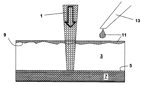
Fig. 2 shows the effect of a liquid 11, such as water,
for example, that wets the rough, light-scattering
surface 9 of the workpiece 3. With a dispenser unit 13
in the form of a spout, pipette or other liquid port,
the liquid 11 is applied, before or in the course of
marking or inscribing, to the rough, light-scattering
surface 9. The surface 9 is therefore optically
smoothed, since the refractive index of the liquid 11
is similar to that of the material of the workpiece 3,
which is a glass substrate. In this case there are no
diffuse reflections at the boundary layer between
workpiece 3 and liquid 11.
Consequently a larger proportion of the laser beam 1 is
coupled into the workpiece 3, and so the method is more
efficient and, even without increasing the laser power,
it is possible to obtain a sufficient transfer of
energy to the polymer matrix 7 for marking or
inscribing. In this case, indeed, the exposure to the
laser beam 1 produces local pulverization and
CA 02680925 2009-09-29
- 11 -
depolymerization in the polymer matrix 7, with
constituents of the polymer matrix or products formed
therefrom being deposited in the form of a marking or
inscription on the surface 5 of the workpiece 3.