Language selection

Search

Patent 2681016 Summary

Third-party information liability

Some of the information on this Web page has been provided by external sources. The Government of Canada is not responsible for the accuracy, reliability or currency of the information supplied by external sources. Users wishing to rely upon this information should consult directly with the source of the information. Content provided by external sources is not subject to official languages, privacy and accessibility requirements.

Claims and Abstract availability

Any discrepancies in the text and image of the Claims and Abstract are due to differing posting times. Text of the Claims and Abstract are posted:

  • At the time the application is open to public inspection;
  • At the time of issue of the patent (grant).
(12) Patent: (11) CA 2681016
(54) English Title: METHOD AND DEVICE FOR SEPARATING OR CLASSIFYING MATERIAL TO BE FED
(54) French Title: PROCEDE ET DISPOSITIF DE SEPARATION OU DE CLASSEMENT DE MATERIAU CHARGE
Status: Granted
Bibliographic Data
(51) International Patent Classification (IPC):
  • B07B 1/14 (2006.01)
  • B07B 1/15 (2006.01)
(72) Inventors :
  • KUPPER, DETLEV (Germany)
(73) Owners :
  • POLYSIUS AG (Germany)
(71) Applicants :
  • POLYSIUS AG (Germany)
(74) Agent: SMART & BIGGAR LP
(74) Associate agent:
(45) Issued: 2015-01-06
(86) PCT Filing Date: 2008-03-19
(87) Open to Public Inspection: 2008-10-23
Examination requested: 2013-02-28
Availability of licence: N/A
(25) Language of filing: English

Patent Cooperation Treaty (PCT): Yes
(86) PCT Filing Number: PCT/EP2008/053328
(87) International Publication Number: WO2008/125415
(85) National Entry: 2009-09-15

(30) Application Priority Data:
Application No. Country/Territory Date
10 2007 018 092.8 Germany 2007-04-17

Abstracts

English Abstract

The device (100) according to the invention for separating or classifying material (1) to be fed into at least two different grain fractions (2, 3) comprises a screen device (5), which is formed by rotatable elements (8), particularly a roller table screen, wherein at least one finer grain fraction (2) passes between the rotatable elements (8) and means (14) are provided for cooling the rotatable elements.


French Abstract

L'invention concerne un dispositif de séparation ou de classement de matériau chargé en au moins deux fractions granulométriques différentes comportant un dispositif de tamisage, lequel est constitué d'éléments rotatifs, en particulier d'une grille à disques, au moins une fraction granulométrique plus fine tombant entre les éléments rotatifs et un moyen de refroidissement des éléments rotatifs étant prévu.

Claims

Note: Claims are shown in the official language in which they were submitted.


8
Claims
1. A plant for the heat treatment of feedstock having a
pre-heater for pre-heating the feedstock and a rotary
tubular kiln for burning the pre-heated feedstock, wherein a
device for separating or classifying feedstock into at least
two different grain fractions is arranged between the pre-
heater and the rotary tubular kiln, the device having a
screen device which is formed by rotatable elements, at
least one finer grain fraction falling through between the
rotatable elements and means being provided for supplying a
cooling medium to the rotatable elements; and
wherein the rotatable elements have a basic body and
an outer casing, the basic body having a duct which extends
in the direction of its axis of rotation and which can be
acted upon by a cooling medium and which is connected to the
means for supplying the cooling medium.
2. The plant according to claim 1, wherein the screen
device is in the form of a roller table screen and the
rotatable elements are in the form of rollers or cylinders.
3. The plant according to claim 1, wherein at least some
of the rotatable elements are connected to a drive.
4. The plant according to claim 1, wherein the distance
between at least some of the rotatable elements is
adjustable.
5. The plant according to claim 1, wherein the rotatable
elements are provided inside a housing and the rotatable
elements are supported in bearings which are arranged
outside the housing.


9
6. The plant according to claim 5, wherein the bearings
have means for cooling.
7. The plant according to claim 1, wherein the outer
casing of the rotatable elements is wear-resistant and/or
temperature-resistant.
8. The plant according to claim 1, wherein material guide
elements are provided between two adjacent rotatable
elements.
9. The plant according to claim 1, wherein there are
provided between two adjacent rotatable elements, means for
cleaning the nip between the two rotatable elements.
10. The plant according to claim 1, wherein the rotatable
elements have a non-circular shape but a substantially
constant nip remains between two adjacent rotatable elements
during the rotational movement.
11. A method for heat treatment of feedstock wherein the
feedstock is pre-heated in a pre-heater and burnt in a
rotary tubular kiln, the method comprising:
providing a feedstock and a device for separating or
classifying which is arranged between a pre-heater and a
rotary tubular kiln;
feeding the feedstock into the device, the feedstock
being separated or classified into at least two different
grain fractions in the device, wherein at least one finer
grain fraction is falling through between rotatable elements
of a screen device and the rotatable elements are cooled by
a cooling medium; and


10
wherein the rotatable elements have a basic body and an
outer casing, the basic body having a duct which extends in
the direction of its axis of rotation and which is acted
upon by the cooling medium.
12. The method according to claim 11, wherein at least some
of the rotatable elements are driven.
13. The method according to claim 11, wherein the direction
of rotation and/or the speed of rotation of the rotatable
elements is alterable.
14. The method according to claim 11, wherein the feedstock
has a temperature of at least 250°C.
15. The method according to claim 11, wherein the feedstock
has a temperature of at least 750°C.

Description

Note: Descriptions are shown in the official language in which they were submitted.


CA 02681016 2009-09-15
1
Method and device for separating or classifying material to
be fed
The invention relates to a method and a device for
separating or classifying feedstock into at least two
different grain fractions, with a screen device which is
formed by rotatable elements, especially a roller table
screen, at least one finer grain fraction falling through
between the rotatable elements.
In the field of the heat treatment of raw materials,
especially in the pre-heating or calcination of raw
materials of the cement or lime industry, a separation or
classification of the material is often necessary between
two heat treatment steps. For that purpose, for example,
classifying screens and fluidised bed devices are used.
Owing to the hot material, which may have temperatures of
more than 75000, blockages and restrictions in the operation
of the screen device occur constantly.
DE-AS-1 124 892 discloses a rotary bar screen system or
sieve bottom system which can be cooled or heated by means
of electrical energy, liquids or gases. A cooled
classifying screen has, however, not been used hitherto in
the heat treatment of raw materials, especially during the
pre-heating or calcination of raw materials of the cement or
lime industry.
The object of the invention is to improve the method and the
device for separating or classifying feedstock in the field
of the heat treatment of raw materials, especially during
the pre-heating or calcination of raw materials of the
cement or lime industry.

CA 02681016 2014-06-06
2
The device according to the invention for separating or
classifying feedstock into at least two different grain
fractions has a screen device which is formed by rotatable
elements, especially a roller table screen, at least one
finer grain fraction falling through between the rotatable
elements and means being provided for supplying a cooling
medium to the rotatable elements. The rotatable elements
have a basic body and an outer casing, the basic body
providing a duct which extends in the direction of its axis
of rotation and which can be acted upon by the cooling
medium and which is connected to the means for supplying the
cooling medium.
Although roller table screens are known in other fields,
especially in coaling plants, those roller table screens are
used only at ambient temperatures. Use under extreme
conditions, such as prevail, for example, during the pre-
heating or calcination of raw materials of the cement or
lime industry, has hitherto still not been proposed.
The outer casing has, in particular, a wear-protection
and/or temperature-protection function, whilst the basic
body is used as a carrying body, the carrying capacity
thereof being markedly increased by the cooling operation.
In the method according to the invention, the feedstock has
a temperature of at least 250 C, especially of at least
750 C. Owing to the provision of the means for cooling the
rotatable elements, the roller table screen can be used
under those extreme conditions.

CA 02681016 2014-06-06
3
The screen device is preferably in the form of a roller
table screen and the rotatable elements are in the form of
rollers or cylinders. The rotatable elements are used as
conveying elements for a larger grain fraction and at least
some of them are driveable for that purpose.
According to a preferred embodiment, insulation can be
provided between the outer casing and the basic body, so
that inexpensive cooling of the basic body by means of air
may be considered.
The rotatable elements are advantageously supported outside
the housing, it being additionally possible to provide for
the bearings to be cooled.
The device for separating or classifying feedstock is
preferably used in a plant for the heat treatment of
feedstock, especially raw material, having a pre-heater for
pre-heating the feedstock, and a rotary tubular kiln for
burning the feedstock. The device for separating and
classifying is arranged between the pre-heater and the
rotary tubular kiln.
)5
Further advantages and configurations of the invention will
be explained in more detail hereinafter by means of the
description and the drawings.
Figure 1 is a diagrammatic view in longitudinal section of
the device according to the invention for separating or
classifying feedstock,

CA 02681016 2009-09-15
4
Figure 2 is a diagrammatic side view in the region of a
rotatable element,
Figure 3 is a sectional view of a rotatable element,
Figure 4 is a sectional view in the region of adjacent
rotatable elements with a material guide element,
Figure 5 is a sectional view in the region of adjacent
rotatable elements with means for cleaning the nip between
the two rotatable elements,
Figure 6 to Figure 8 are various cross-sectional views of
the rotatable elements and
Figure 9 is a diagrammatic view of a plant for the heat
treatment of feedstock.
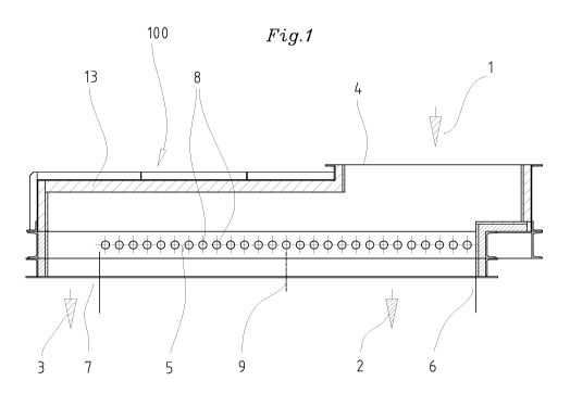
The device 100 shown in Figure 1 and Figure 2 for separating
or classifying feedstock 1 into at least two different grain
fractions 2, 3 has a feed opening 4, a screen device 5 in
the form of a roller table screen and at least one outlet
opening 6 for a finer grain fraction 2 and an outlet opening
7 for a coarser grain fraction 3.
The screen device 5 provides a large number of rotatable
elements 8 in the form of rollers or cylinders, at least
some of which are driveable. The finer grain fraction 2
falls through between the rotatable elements 8, so that the
distance between two adjacent rotatable elements determines
the size of the finer grain fraction 2. The distance may be
the same or different over the length of the screen.
Preferably, the distance between adjacent rotatable elements
8 is adjustable.

CA 02681016 2009-09-15
In Figure 1, it is indicated by means of the wall 9 drawn
with a broken line that different grain fractions could be
drawn off as screened matter over the length of the screen
5 device 5. For that purpose, the distance between the
rotatable elements 8 in the first portion of the screen
device 5 would be made narrower than in the second section.
The coarser grain fraction 3, which does not fall downwards
between the rotatable elements 8, is conveyed by the
rotatable elements to the outlet opening 7. The rotatable
elements therefore also have a conveying function in
addition to the separating or classifying function.
The rotatable elements 8 are supported in bearings 10, 11
and can be driven by means of suitable drive means 12 (shown
only schematically in the drawing). The bearings 10, 11 are
advantageously arranged outside a housing 13 of the device
100 in order to protect them from the effects of dust and
temperature.
As can be seen from Figures 2 and 3, the rotatable element 8
comprises a basic body 8a and a suitably wear-resistant
and/or temperature-resistant casing 8b in order to ensure a
sufficient service life in the processing of the feedstock.
Suitable insulation 8c can optionally also be provided
between the basic body 8a and the casing 8b.
The basic body 8a has a duct 8d which extends in the
direction of its axis of rotation 8e and which can be acted
upon by a cooling medium and which is connected to means 14
for supplying a cooling medium. Liquid and/or gaseous
coolant media, such as water or air, may be considered.
Means for cooling, which are not shown in detail, can also
be provided for the bearings 10, 11.

= CA 02681016 2009-09-15
6
The screen device 5 can be arranged to be both horizontal
and inclined. In both cases, it may be advantageous if a
material guide element 15 is provided between two adjacent
rotatable elements 8 in order to prevent an undesirable
filling of the space between the two cylinders and thereby
to improve the conveying action (Figure 4).
Nevertheless, larger particles will continue to become stuck
in the region of the nip and thereby impair the separating
or classifying action. The rotatable elements 8 could
therefore be constructed and supported in such a manner that
a comminution of such material takes place in the nip
between two adjacent rotatable elements 8.
A further possibility for removing any blockages in the nip
between two rotatable elements 8 is shown in Figure 5. What
is involved here is means or an element 16 for cleaning the
nip as a result of the fact that this element is arranged
beneath the nip and can be inserted upwards into the nip.
The cross-sectional shape of the rotatable elements 8 is in
no way limited to a circular shape. Figures 6 to 8 show
various cross-sectional shapes of the rotatable elements 8.
The characteristic feature of those elements resides in the
fact that, when they are rotated synchronously, a
substantially constant nip remains. The advantage of an
elliptical element (Figure 6), a cross-sectionally
triangular (Figure 7) or rectangular element (Figure 8)
having rounded side faces consists above all in the improved
conveying action.
In the context of the invention, however, it is of course
also possible to use identical or differently shaped

CA 02681016 2009-09-15
7
rotatable elements 8 over the length of the screen device.
Different sizes of a specific shape can also be provided
for.
Generally, all of the rotatable elements 8 are driven in the
same direction of rotation, it being possible to provide for
regulation of the speed of all or some of the rotatable
elements.
In order to clear any blockages in the region of the nips,
it may also be advantageous to drive the rotatable elements
8 for a short period counter to the normal direction of
rotation.
Figure 9 shows very schematically a plant for the heat
treatment of feedstock. The plant has, in particular, a
pre-heater for pre-heating the feedstock, especially raw
material, a device 100 for separating or classifying
feedstock, and a rotary tubular kiln for burning the pre-
heated feedstock. The device 100 for separating or
classifying feedstock is arranged between the pre-heater 200
and the rotary tubular kiln 300 in order to separate out a
grain fraction which is undesirably fine for the rotary
tubular kiln.

Representative Drawing
A single figure which represents the drawing illustrating the invention.
Administrative Status

For a clearer understanding of the status of the application/patent presented on this page, the site Disclaimer , as well as the definitions for Patent , Administrative Status , Maintenance Fee  and Payment History  should be consulted.

Administrative Status

Title Date
Forecasted Issue Date 2015-01-06
(86) PCT Filing Date 2008-03-19
(87) PCT Publication Date 2008-10-23
(85) National Entry 2009-09-15
Examination Requested 2013-02-28
(45) Issued 2015-01-06

Abandonment History

There is no abandonment history.

Maintenance Fee

Last Payment of $473.65 was received on 2023-03-06


 Upcoming maintenance fee amounts

Description Date Amount
Next Payment if small entity fee 2024-03-19 $253.00
Next Payment if standard fee 2024-03-19 $624.00

Note : If the full payment has not been received on or before the date indicated, a further fee may be required which may be one of the following

  • the reinstatement fee;
  • the late payment fee; or
  • additional fee to reverse deemed expiry.

Patent fees are adjusted on the 1st of January every year. The amounts above are the current amounts if received by December 31 of the current year.
Please refer to the CIPO Patent Fees web page to see all current fee amounts.

Payment History

Fee Type Anniversary Year Due Date Amount Paid Paid Date
Application Fee $400.00 2009-09-15
Maintenance Fee - Application - New Act 2 2010-03-19 $100.00 2010-02-19
Maintenance Fee - Application - New Act 3 2011-03-21 $100.00 2011-02-17
Maintenance Fee - Application - New Act 4 2012-03-19 $100.00 2012-03-15
Maintenance Fee - Application - New Act 5 2013-03-19 $200.00 2013-02-21
Request for Examination $800.00 2013-02-28
Maintenance Fee - Application - New Act 6 2014-03-19 $200.00 2014-02-19
Final Fee $300.00 2014-10-20
Maintenance Fee - Patent - New Act 7 2015-03-19 $200.00 2015-03-09
Maintenance Fee - Patent - New Act 8 2016-03-21 $200.00 2016-03-08
Maintenance Fee - Patent - New Act 9 2017-03-20 $200.00 2017-03-06
Maintenance Fee - Patent - New Act 10 2018-03-19 $250.00 2018-03-06
Maintenance Fee - Patent - New Act 11 2019-03-19 $250.00 2019-03-11
Maintenance Fee - Patent - New Act 12 2020-03-19 $250.00 2020-03-09
Maintenance Fee - Patent - New Act 13 2021-03-19 $255.00 2021-03-08
Maintenance Fee - Patent - New Act 14 2022-03-21 $254.49 2022-03-07
Maintenance Fee - Patent - New Act 15 2023-03-20 $473.65 2023-03-06
Owners on Record

Note: Records showing the ownership history in alphabetical order.

Current Owners on Record
POLYSIUS AG
Past Owners on Record
KUPPER, DETLEV
Past Owners that do not appear in the "Owners on Record" listing will appear in other documentation within the application.
Documents

To view selected files, please enter reCAPTCHA code :


To view images, click a link in the Document Description column. To download the documents, select one or more checkboxes in the first column and then click the "Download Selected in PDF format (Zip Archive)" or the "Download Selected as Single PDF" button.

List of published and non-published patent-specific documents on the CPD .

If you have any difficulty accessing content, you can call the Client Service Centre at 1-866-997-1936 or send them an e-mail at CIPO Client Service Centre.


Document
Description 
Date
(yyyy-mm-dd) 
Number of pages   Size of Image (KB) 
Abstract 2009-09-15 1 11
Claims 2009-09-15 3 83
Drawings 2009-09-15 9 95
Description 2009-09-15 7 268
Representative Drawing 2009-09-15 1 9
Cover Page 2009-11-26 2 39
Claims 2012-02-28 3 88
Description 2014-06-06 7 261
Claims 2014-06-06 3 87
Cover Page 2014-12-11 1 37
Fees 2010-02-19 1 36
PCT 2009-09-15 6 221
Assignment 2009-09-15 5 130
Fees 2011-02-17 1 36
Prosecution-Amendment 2013-02-28 5 149
Prosecution-Amendment 2014-02-27 2 65
Prosecution-Amendment 2014-06-06 8 244
Correspondence 2014-10-20 1 50