Note: Descriptions are shown in the official language in which they were submitted.
CA 02681040 2009-09-15
WO 2008/116891
PCT/EP2008/053602
SUPER HIGH TORQUE DOPE-FREE THREADED JOINT
FIELD OF THE INVENTION
[0001] This invention is directed to a high torque threaded joint having a
flank-to-
flank contact thread profile, trapezoidal threads with both a positive and
very low load
flank angle, [131 or a.] ; and a positive and very low stabbing flank angle,
[132 or b.],
wherein the threads are coated with a solid, dope-free surface treatment .
BACKGROUND OF THE INVENTION
[0002] In the oil and gas industries, there is a need for a threaded joint
having "super
high torque performance," which numerically means an overtorque capacity of
about
40% of pipe body resistance. Conventional technologies generally provide up to
about 20% overtorque capacity. There is limited prior art technology which is
capable of reaching super high torque performance. One technology requires a
wedge
thread, and is illustrated by U.S. Patent No. Re. 34,467 (Reeves) and WO
94/29627
(Mott). U.S. Patent No. 6,412,831 (Noel et al.) discloses a variation on the
wedge
thread to achieve a high tightening torque.
[0003] The tapered wedge threads described in U.S. Patent No. Re. 34,467 are
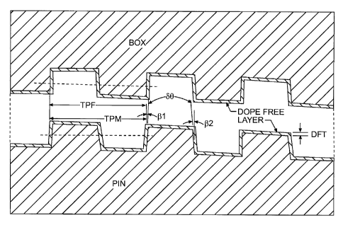
known
to provide an unusually strong connection that can control the stress and
strain of the
connected pin and box members within acceptable levels. For this reason, wedge
threads are employed in many heavy-duty applications. The wedge threads
generally
have a dovetail shape, with load flanks and stab flanks that diverge outwardly
to
create crests that are substantially wider than the contiguous roots. This
creates an
interlocking thread form configuration, and the threads do not rely on
shoulders to
bear loads caused by make up. The dovetail shape of the threads, however,
presents a
problem in that unless the axial alignment of the joints is perfect during
make up and
break down, the edges of the threads of the pin and the box may contact. Such
contact can prevent the pin from completely penetrating the box during make up
and
can cause damage to the threads.
[0004] WO 94/29627 is another example of wedge threads, having wider crests
than
the respective roots and both stab flanks and load flanks generally angled in
the same
direction, or with positive and negative angles as conventionally measured
with
respect to the longitudinal axis of the connection. Such a configuration can
decrease
CA 02681040 2009-09-15
WO 2008/116891
PCT/EP2008/053602
2
the chances that the thread edges will come into contact during make up and
break
down, thus, minimizing risk of thread damage.
[0005] However, the wedge thread configurations disclosed in the '627
publication,
and the '467 patent have the common disadvantage of a very low energy
absorption to
the final torque point; a low fatigue resistance due to the high stress
present in the last
engaged thread; and a higher tendency to disengagement, which commonly is
known
as spring back. Such wedge thread connections require tight machining
tolerances,
which makes them difficult and expensive to manufacture, as well as difficult
to
inspect for defects. Still further, the acute angles of the wedge threads
disposed on
the load flank side and/or the stabbing flank side have sharp cuts that are
deleterious
to the function of the connection. Such threads also become more fragile
during use
as a consequence of thread root notching, that is caused by the shape angles.
[0006] U.S. Patent No. 6,412,831 discloses a threaded connection of two metal
pipes,
which includes a tapered thread with one type of male trapezoidal threads on a
pin
element and a mating female trapezoidal thread on the box element. While the
width
of the thread at the crest is less than the width of the thread at the root,
that is achieved
by a small, negative load flank angle (a. is preferably -3 ) paired with a
much larger
positive stabbing flank angle (b. is preferably 13 ), which combine to define
an
included angle ( 6e) between the load flank and stabbing flank surfaces that
still is
positive (preferably 10 ). While the male and female elements are said to able
to
reach a position beyond where two flanks of the male thread come into contact
with
two flanks of the female thread, it is emphasized that a viscous grease form
of dope
critically is required. (See column 8, line 46).
[0007] Hence, achieving a makeup with a higher torque requires a viscous
grease
with the modified wedge thread geometry illustrated in the '831 patent. This
is
disadvantageous. While there might not be any radial interference, the
presence of
the viscous dope creates a high pressure in both the crests and the roots,
which
diminishes the contact pressure between flanks, and results in a decrease in
torque.
For these reasons, as well as for environmental reasons, it is highly
desirable to avoid
the use of dope in order to reach a high torque value.
[0008] The advantages and disadvantages of conventional dope or grease (i.e.,
API
5A3, which is an API modified grease) as a thread treatment is known. A
particular
CA 02681040 2014-05-23
3
class of dry thread pretreatments, which do not require the application of
dope or
grease as a lubricant, also now are known, and such dry thread pretreatments
are
broadly referred to herein as "dope-free".
[0009] Reference may be made to the disclosures of U.S. Patent Application
Publication No. 2005/0176592 Al for further details of a dope-free dry
lubricant
coating achieved by applying a dry film including an intrinsically conductive
polymer
to a thread surface. Reference may also be made to the disclosures of U.S.
Patent No.
6,971,681 B2, for details of dry surface treatments of threads for use in the
oil and gas
extraction industry that increase both the corrosion resistance and galling
resistance of
a connection joint.
SUMMARY OF THE INVENTION
[0010] In one aspect, the present invention is directed to a threaded joint
comprising a
box member having threads and a pin member having threads configured and
positioned to mate with the threads of the box member, wherein the box member
and
the pin member each have a flank-to-flank contact thread profile and low and
positive
load flank angles [131 or a.] and low and positive stabbing flank angles [132
or b.] which
match on mating pins and boxes. The low and positive flank angles should be
approximately 30 to approximately 15 , more preferably approximately 30 to
approximately 10 , and most preferably approximately 3 to approximately 5 ,
as
conventionally measured from a vertical axis that is normal to the centerline
of the
connection. These combinations of low, positive angle values define a
trapezoidal
thread with an included angle between the two flank surfaces of a thread (.3o)
that will
range from between 6 and 30 and preferably will be 8 . The threads of at
least one
of the box member and the pin member also may be chamfered.
[0011] The machined threads on either or both the box member and the pin
member
then are pretreated with a dope-free surface coating. The dope-free surface
coating
allows for full compliance with a disclosed mathematical model and avoids the
effect
of a pressure difference as between a make up and a break out. The unique
combination of dope-free surface treatments and low, positive values for both
the load
and stabbing flank angles, cooperates to produce a surprisingly high torque
connection that is consistent in either a make up or a break out of the
connection. A
CA 02681040 2009-09-15
WO 2008/116891
PCT/EP2008/053602
4
high make-up and break-out torque is particularly advantageous for drilling
operations
employing rotation tools, because it reduces greatly the risk of disengagement
(spring
back).
[0012] These and other aspects of the present invention will be apparent upon
consideration of the following detailed description taken in conjunction with
the
accompanying drawings, in which preferred embodiments of the present invention
are
described and illustrated.
BRIEF DESCRIPTION OF THE DRAWINGS
[0013] FIG. 1 schematically depicts, in explosion view, a thread configuration
of a
box and pin with trapezoidal threads each having a dope-free coating,
according to
the present invention, and
[0014] FIG. 2 schematically depicts, in explosion view, a
preferred thread
configuration of a box and pin with trapezoidal threads chamfered or rounded
between each flank surface and an adjoining crest surface or root surface,
each surface
of the threads having a dope-free coating according to the present invention,
and
[0015] FIG. 3 depicts positive, low load and stabbing flank angles for a
modified
buttress type of trapezoidal thread configuration of a pin with preferred
dimensions
according to an embodiment of the present invention, and
[0016] FIG. 4 depicts positive, low load and stabbing flank angles for a
modified
buttress type of a trapezoidal thread configuration of a box with preferred
dimensions
according to an embodiment of the present invention, and
[0017] FIG. 5 is a TABLE illustrating variation of maximum torque for
different
configurations, with either an API dope or a dope-free coating, according to
the
present invention, and
[0018] FIG. 6 is a GRAPH illustrating variation of maximum torque for
different low
load and stabbing flank angle combinations, as a function of different
interference
values, according to the present invention, and
[0019] FIG. 7 is a GRAPH illustrating variation of maximum torque as a
function of
different low to higher stabbing flank angles, according to the present
invention.
[0020] FIG. 8 is a TABLE illustrating variation of maximum torque for
different
configurations of thread geometry according
to the present invention.
CA 02681040 2009-09-15
WO 2008/116891
PCT/EP2008/053602
DETAILED DESCRIPTION OF THE PRESENT INVENTION
[0021] The present invention is directed to providing a threaded joint having
a flank-
to-flank contact thread profile that is defined by trapezoidal threads with
both a
positive and very low load flank angle, [131 or a.] , and a positive and very
low stabbing
flank angle, [132 or b.]. Specifically, the present invention is directed to
providing a
threaded joint comprising a box member and a pin member each having a flank-to-
flank contact due to a trapezoidal thread profile with a preferred included
angle
between flanks of about 8 that is defined by very low, but positive load and
flank
angles that preferably each are between about 3 and 5 . Such threads for a
box and
the pin schematically are shown in FIGS 1 and 2 after machining, and also
after
application of a dope-free coating.
[0022] FIGS. 3 and 4 schematically show details preferred embodiment,
comprising
an OD of 3.5 inches and a modified buttress thread shape, wherein chamfers or
rounds
are applied to intersections of flank surfaces with either a crest surface or
a root
surface, and without the dope-free coating for clarity . FIG. 3 illustrates
preferred,
positive load and stabbing flank angles for a trapezoidal thread configuration
of a pin
with preferred dimensions according to embodiments of the present invention.
FIG. 4
illustrates preferred, positive load and stabbing flank angles for a
trapezoidal thread
configuration of a box with preferred dimensions according to an embodiment of
the
present invention. The threads of the pin portion of the threaded joint and
the pin
portion of the threaded joint each have a load flank angle [131 or a.] of
about 3 , and a
stabbing flank angle [132 or b.] of about 5 . The present invention, however,
is not
limited and contemplates useful, positive flank angles from approximately 3
to
approximately 15 as measured from a plane perpendicular to the centerline of
the
connection. Preferably, the flank angle ranges from approximately 3 to
approximately 10 . As shown in FIGS. 3 and 4, a load flank angle of 3 and a
stabbing
flank angle of 5 is defined by the machining. The thin layer of a dope free
coating to
be applied to the threads of either or both the pin and the box after
machining is very
thin and uniform, and does not alter the geometry.
[0023] The following mathematical model derived from the mathematical theory
of
elasticity is used to calculate the expected torque for a determinate profile
as a
function of the thread flank angles:
CA 02681040 2009-09-15
WO 2008/116891
PCT/EP2008/053602
6
[sec(A) + sec(/32)] L
T = ,u = A - = .5 = E = (b2 _ a2). (c2 _ b2 ).
(1- v2 ) = b = (c 2 - a 2 ) tan(A ) + tan(32 ) + b = v (1)
where:
T = torque;
1..t, = coefficient of friction;
6 = radial interference;
E = elasticity module;
a = internal radius;
b = thread medium radius;
131 = load flank angle;
132 = stabbing flank angle;
u = Poisson coefficient; and
L = axial length of an active complete thread.
C = external radius
[0024] Once the preferred flank profile of the pin and box has been
determined, and
box and pin members have been machined based on the preferred flank profile,
the
joint could be made up in either a doped or a dope-free state. However, it has
been
discovered that use of a viscous dope causes deviation from the above
mathematical
model due to the pressurized flow or movement over time of viscous dope
trapped
between flank surfaces and in spaces between a crest and a root portion of a
mated
thread. The dope in such a scenario can act as a non-compressive media
homogenizing pressures in the crests and roots. The presence of the dope,
therefore,
has been found to make it very difficult to obtain full flank-to-flank contact
at make-
up. Surprisingly, the dope-free dry layer configurations taught herein allow
for full
compliance with the mathematical model. Additionally, with a dope-free coating
the
desired full flank-to-flank contact can be obtained at the initial make up of
the joint,
and there is no variation in time as with viscous dope.
[0025] In addition to the flank-to-flank contact thread profile and low flank
angles,
the thread profile according to the present invention preferably also include
chamfers
or rounded corners at intersections of a flank surface with a crest or root
surface, in
order to improve thread stabbing, as illustrated in FIGS 1 , 3 and 4. The
crest and the
root surfaces may have any profile and chamfer shape that is consistent with
the
angles for the load flank and stabbing flank surfaces that are disclosed
herein. The
CA 02681040 2009-09-15
WO 2008/116891
PCT/EP2008/053602
7
present invention is not limited to any particular root or crest surface shape
and
modifications such as including a groove in one or both of the root and crest
may be
made without departing from the scope of the present invention. Additionally,
the
joint may be constructed with or without a torque shoulder. For example, if
the
torque is high enough, make up can be defined by position, without the need
for a
torque shoulder. Examples 1 and 2 do not include a torque shoulder. Examples 3
and
4 do include a torque shoulder.
[0026] Radial interference [6 ] values for all embodiments are low and
preferably
range from about 0 to about 0.5 mm.
[0027] The connection of the present invention can be applied to every type of
connection, particularly either in cases when the female member is formed at
an end
portion of a pipe or when a sleeve with two female members at both ends to
join two
male pipes is used. Useful materials for the connection are common carbon
steels,
stainless steels, or chromium alloy steels having a yield strength from about
552
MPa(80 ksi) to about 1034 MPa (150 ksi) and a preferred connection employs a
grade
L80 API steel. While a 3.5 inch OD embodiment is illustrated by FIGS 3 and 4,
preferred examples which follow are for a 4.5 inch OD connection and a 7 inch
OD
connection, which also are common API connector dimensions.
[0028] The trapezoidal thread combinations illustrated in explosion view by
FIGS. 1
and 2 are provided to provide a schematic definition of particular references
as used
herein. The box and pin are characterized by tapered male and female threads
that
have a common load flank angle, 131, a common stabbing flank angle 132; a male
thread
pitch TPM that is the same as the female thread pitch, TPF and an included
angle
between the two flank surfaces of each male or female thread (6e) which is
positive
and less than about 20 0. As illustrated, the stabbing flank surfaces and load
flank
surfaces will make a substantial surface contact when mated. Upon those thread
surfaces a thin dope-free layer comprising a dry lubricant has been applied,
with a
thickness, DFt, that is on the order of 10-20 m in thickness. FIG. 2 differs
from FIG.
1 in that the flank surfaces intersect root and crest surfaces with a rounded
or
chamfered transition.
[0029] FIGS. 3 and 4 illustrate more details and dimensions of one embodiment
having preferred, chamfered trapezoidal threads for both flank and stabbing
surface
contact between a pin and a box respectively, with the dope-free coating not
shown
CA 02681040 2009-09-15
WO 2008/116891
PCT/EP2008/053602
8
for clarity. This illustration is for a modified buttress thread of 5 threads
per inch,
with flank to flank contact geometry. The following dimensions are
representative for
an OD of 3.5 inches, and demonstrate flank to flank contact geometry using
very low,
but positive load flank angles and very low, but positive stabbing flank
angles.
[0030] FIG 3 illustrates a pin with a tapered male thread 10 of the modified
buttress
type with a load flank surface 12, a stabbing flank surface 14, a male thread
crest
surface 16, and a male thread root surface 18. The male thread pitch line 11
is spaced
a distance 13 from crest that is .74 mm. The distance 15 between the root and
crest
surface is 1.27 mm. The thread width 17 at the pitch line is 2.54 mm. The
flank
surface spacing 19 at the pitch line is 2.54 mm. The low but positive load
flank angle
131 is 3 and the low but positive stabbing flank angle 132 is 5 . The
included angle
between flank surfaces 6,9 is 8 . The thread pitch TPM of the box is 5.08 mm.
The
load flank chamfer R1 is 0.2 mm and the load flank round R2 is 0.2mm.
[0031] FIG 4 illustrates a box with a tapered female thread 20 of the modified
buttress type with a load flank surface 22, a stabbing flank surface 24, a
female thread
crest surface 26, and a female thread root surface 28. The female thread pitch
line 21
is spaced a distance 23 from crest that is .74 mm. The distance 25 between the
root
and crest surface is 1.27 mm. The thread width 27 at the pitch line is 2.54
mm. The
flank surface spacing 29 at the pitch line is 2.54 mm. The low but positive
load flank
angle 131 is 3 and the low but positive stabbing flank angle 132 is 5 . The
included
angle between flank surfaces 6,9 is 8 . The stabbing flank round R3 is 0.4 mm
and the
stabbing flank chamfer R4 is 0.4 mm.
DETAILED EXAMPLES
Example 1
[0032] In this first embodiment, the box and pin members have a flank-to-flank
contact thread profile with a low, positive load flank angle [131 or a. = 3 ]
and a low,
positive stabbing flank angle [132 or b. = 5 ] for both the box member and
pin
members so as to define a trapezoidal thread with an included angle between
flanks 6,9
of 8 . Further parameters of this first example include:
Weight: 12.7 ppf;
Tpi: 5 ;
u: 0.32 (carbon steel)
OD: 4.5"; and
CA 02681040 2014-05-23
9
6 (radial interference): 1.5 x 10⁴ m
The joint of this embodiment was made up with use of a dope, and particularly
API
5A3, which is an API modified grease. As can be seen from Tablesl -1 and 1-2,
below, the breakout torque was higher than the makeup torque making a
significant
difference as compared to with the use of dope-free technology, as shown below
in
Example 2. Also, note that the maximum torque values are much lower as
compared
to with the use of dope-free technology.
Table 1-1
Makeup Maximum Shoulder Delta Shoulder Delta RPM at Final
Run Torque Torque Torque Turns Turns Shoulder Turns
(ft-lbs.) (ft-lbs.) (ft- (revs) (revs)
lbs.)
1 2850 0 0 0 0 0 1.934
2 2316 0 0 0 0 0 1.646
Table 1-2
Breakout Maximum Final
Run Torque Turns
(ft-lbs.)
1 6299 2.833
Example 2
[0033] In this second embodiment, the same material and thread configuration
of
Example 1 is employed. The box and pin members have a flank-to-flank contact
thread profile, a low, positive load flank angle [131 or a.] of 30 and a low,
positive
stabbing flank angle [I32 or b.] of 5 for both the box member and the pin
member, so
as to define a trapezoidal thread with an included angle between flanks [6o]
of 8 . The
joint of this embodiment was made up with use of a two layer, dope-free
solution
coating that exhibited a dry lubricant and anticorrosion properties, according
to the
teachings of US 6,971,681 B2. The first uniform layer was approximately 10 m
in
thickness and comprised an epoxy resin containing particles of Zn as a dry
corrosion
inhibiting coating. The first layer was covered by a second uniform layer
approximately 10um in thickness and comprised a mixture of
CA 02681040 2009-09-15
WO 2008/116891
PCT/EP2008/053602
MoS2 in an inorganic binder as a dry lubricant coating. As can be seen from
Tables 2-
1 and 2-2, below, the make up and break out torque values are significantly
higher
than the make up and break out torques of the equivalent dope embodiment, as
detailed by Tables 1-1 and 1-2, above.
Table 2-1
Makeup Maximum Shoulder Delta Shoulder Delta RPM at Final
Run Torque Torque Torque Turns Turns Shoulder Turns
(ft-lbs.) (ft-lbs.) (ft- (revs) (revs)
lbs.)
1 10830 0 0 0 0 0 1.032
2 10320 0 0 0 0 0 0.93
Table 2-2
Breakout Maximum Final
Run Torque Turns
(ft-lbs.)
1 10140 1.03
2 9970 0.94
Example 3
[0034] In this third embodiment, both the box and pin members have a flank-to-
flank
contact thread profile, a low, positive load flank angle [131 or a.] of 3 and
a low,
positive stabbing flank angle [132 or b.] of 5 for the box and pin members so
as to
define a trapezoidal thread with an included angle between flanks [6e] of 8 .
The
joint of Example 3 was a 4.5" connection of grade L80 API steel with a torque
shoulder, having a weight of 12.6 pounds per feet (ppf) and a diametrical
interference
between 0 and 0.5 mm. Further parameters of this third embodiment include:
Weight: 12.7 ppf;
Tpi: 5;
u: 0.32 (carbon steel)
OD: 4.5"; and
6 (radial interference): 1.5 x 10⁻⁴.
CA 02681040 2009-09-15
WO 2008/116891
PCT/EP2008/053602
11
The joint of Example 3 was made up with use of a dope, and particularly API
5A3, which is an API modified grease. As can be seen from Tables 3-1 and 3-2,
below, the breakout torque was higher than the makeup torque. Again, there is
a
significant difference as compared to the first embodiment, as detailed above
wherein
a dope-free technology is employed.
Table 3-1
Makeup Maximum Shoulder Delta Shoulder Delta RPM at Final
Run Torque Torque Torque Turns Turns Shoulder Turns
(ft-lbs.) (ft-lbs.) (ft- (revs) (revs)
lbs.)
1 3313 2143 1170 0.011 1.31 5.3 1.31
2 2688 1915 773 0.008 1.038 5.1
1.038
Table 3-2
Breakout Maximum Final
Run Torque Turns
(ft-lbs.)
1 6508 1.58
2 7850 1.263
Example 4
[0035] In this fourth embodiment, the same material and thread configuration
of
Example 3 is employed.
[0036] The box and pin members have a flank-to-flank contact thread profile
and the
load flank angle [131 or a.] is 3 and the stabbing flank angle [132 or b.] is
5 for both
the box member and the pin member, so as to define a positive, included flank
angle
[6e] of 80. The joint of this embodiment was made up with use of a dope-free
solution
coating with both lubricant and anticorrosion properties: a first uniform
layer of a dry
corrosion inhibiting coating and said first layer being covered by a second
uniform
layer of dry lubricant coating. The first uniform layer was approximately 10 m
in
thickness and comprised an epoxy resin containing particles of Zn as a dry
corrosion
CA 02681040 2009-09-15
WO 2008/116891
PCT/EP2008/053602
12
inhibiting coating. The first layer was covered by a second uniform layer
approximately 10 m in thickness and comprised a mixture of MoS2 in an
inorganic
binder as a dry lubricant coating.
[0037] As in Example 3, the joint of Example 4 was a 4.5" OD connection of
grade
L80 API steel with a torque shoulder, having a weight of 12.6 pounds per feet
(ppf)
and a low diametrical interference of between 0 and 0.5 mm.
[0038] As can be seen from Tables 4-1 and 4-2, below, the make up and break
out
torque values are significantly higher than the make up and break out torques
of the
embodiments in the comparative examples utilizing a dope, as shown in Tables 3-
1
and 3-2.
Table 4-1
Make- Max Shoulder Delta Shoulder
Delta RPM at Final
Up Torque Torque Torque Turns Turns
Shoulder Turns
Run (ft- (ft-lbs.) (ft- (revs) (revs)
lbs.) lbs.)
1 13220 10530 2690 0.721 0.022 5.8 0.743
2 12510 10050 2460 0.750 0.031 5.51 0.781
3 12780 10647 2133 0.711 0.029 5.4 0.740
Table 4-2
Breakout Maximum Final
Run Torque Turns
(ft-lbs.)
1 12850 1.12
2 13020 1.45
3 12540 1.52
[0039] From a comparison of dope Example 1 with the comparable structure but
with
a thin dope-free layer comprising a dry lubricant, in Example 2, as well as
from a
comparison of dope Example 3 with the comparable structure but with a thin
dope-
free layer comprising a dry lubricant layer over a corrosion resistant layer,
in Example
CA 02681040 2009-09-15
WO 2008/116891
PCT/EP2008/053602
13
4, surprising results can be seen. By employing, in combination, a thin and
dry, dope-
free solution coating in combination with a trapezoidal thread configuration
having a
very low, positive load flank angle, a very low, positive stabbing flank
angle, and a
flank-to-flank contact profile, it is possible to achieve a much higher torque
value than
by using the same thread geometry but with a conventional grease or dope, both
during the steps of make-up and break out.
[0040] Surprisingly, it also has been found that when using a dope-free
configuration
with very low and positive flank angle, as taught herein, the torque for the
connection
increases depending on the decrement of the positive value of stabbing flank
angle.
That fact is evident from Examples 5 and 6, which follow..
[0041] Furthermore, while in theory that Equation (1) should be valid both to
describe
make up and breakout torques, experimentally it has been discovered that
unless a
thin, dry lubricant and dope-free solution is used, make-up torque value will
reach
lesser values due to the time-dependent pressure changes that are produced by
grease.
Example 5
[0042] In a fifth embodiment, the box and pin members have a flank-to-flank
contact
thread profile, a load flank angle [131 or a.] of 3 and a stabbing flank
angle [132 or b.]
of 7 for both the box member and the pin member, so as to define a positive,
included flank angle [6e] of 100. The joint of this embodiment was made up
with use
of a dope (API 5A3). Data for the make up and breakout of the fifth embodiment
can
be seen in Tables5-1 and 5-2, below.
Table 5-1
Makeup Max Shoulder Delta Shoulder Delta RPM at Final
Run Torque Torque Torque Turns Turns Shoulder Turns
(ft- (ft-lbs.) (ft- (revs) (revs)
lbs.) lbs.)
1 2588 0 0 0 0 0 0.838
2 2488 0 0 0 0 0 0.791
3 2586 0 0 0 0 0 0.882
CA 02681040 2009-09-15
WO 2008/116891
PCT/EP2008/053602
14
Table 5-2
Breakout Maximum Final
Run Torque Turns
(ft-lbs.)
1 2259 1.222
2 2248 1.75
3 2328 2.176
Example 6
[0043] In a sixth embodiment, the box and pin members have a flank-to-flank
contact
thread profile, a load flank angle [131 or a.] of 3 and a stabbing flank
angle [132 or b.]
of 7 for both the box member and the pin member, so as to define a positive,
included flank angle [6e] of 100. The joint of this embodiment was made up
with use
of a dope-free solution coating having lubricating and/or anticorrosion
properties.
[0044] Data for the make up and breakout of the sixth embodiment can be seen
in
Tables 6-1 and 6-2, below.
Table 6-1
Makeup Max Shoulder Delta Shoulder Delta RPM at Final
Run Torque Torque Torque Turns Turns Shoulder Turns
(ft-lbs.) (ft-lbs.) (ft- (revs) (revs)
lbs.)
1 7820 0 0 0 0 0 1.013
2 7840 0 0 0 0 0 0.97
Table 6-2
Breakout Maximum Final
Run Torque Turns
(ft-lbs.)
1 8420 1.02
2 8200 0.98
CA 02681040 2009-09-15
WO 2008/116891
PCT/EP2008/053602
[0045] Example 6 shows that, when the stabbing flank is greater, torque values
of
make-up and break out, are lower, maintaining the same load flank angle and
the
dope-free condition.
[0046] FIG. 5 is a TABLE that shows the variation of torque with different
configurations of load and stabbing flank angles. The first 15 rows define
torque
values for different thread configurations, where the threads conventionally
were
coated with API 5A3 dope. The second 15 rows define torque values for
different
thread configurations, where the threads instead were coated with a dope-free
coating
very similar to the embodiment of Examples 2, 4 and 6 but within a 7" OD
connection.
[0047] FIG. 6 is a GRAPH that shows the variation of torque values for a
representative, 7 inch OD connection with different configurations of load and
stabbing flank angles, as function of radial interference. The bottom three
curves plot
torque values for different thread configurations, where the threads
conventionally
API 5A3 dope were used. The upper three curves plot torque values for
different
thread configurations, where the threads instead were coated with a dope-free
coating
according to the embodiment of Examples 2, 4 and 6 but using a 7" OD
connection.
[0048] FIGS. 7 and 8 are respectively a GRAPH and a TABLE that illustrate the
unexpected result that maximum torque is very dependent upon an unexpected
parameter of thread geometry, and particularly the value of a low, positive
stabbing
flank angle [132 or b.] between about 0.5 and 45 when using a dope-free
coating.
FIG. 8 illustrates in a tubular form representative torque values employing a
dope-free
coating on different trapezoidal threads that each has a constant flank load
angle [131 or
a.] of about 3 .
[0049] FIGS. 7 and 8 also demonstrate the surprisingly higher torques possible
with
dope-free coatings, at very low, positive stabbing flank angles [132 or b.]
approaching a
minimum positive value of about 0.5 . This is believed to be a result of the
far
superior friction factor of a solid, non-viscous dope-free coating. It is
important to
note that this effect will be more notorious in practice due to the above-
mentioned
problem of a viscous dope pressure effect in these types of thread geometries.
[0050] In order to clarify the concept, and using the formula (1), it is
possible to
compare the torque values of a load flank angle of 3 and a stabbing flank
angle that
CA 02681040 2009-09-15
WO 2008/116891
PCT/EP2008/053602
16
varies from 0.5 to 45 . The maximum torque values for a similar dope coated
connection will be much lesser that what is illustrated by FIGS. 7 and 8.
[0051] With a stabbing flaffl( angle that is decreased below 15 , the torque
value
increases notoriously, to torque values that quickly exceed 2,000 lb.ft. It
also can be
seen from FIG 7 that torque variation from varying a stabbing flaffl( angle
between
15 and 45 (or higher) is not significant, so it would not be useful to seek
a high
torque value by choosing a stabbing flaffl( angle higher than 15 .