Note: Descriptions are shown in the official language in which they were submitted.
CA 02681562 2009-09-22
WO 2008/116469 PCT/DK2008/050065
1
A METHOD OF WELDING DUPLEX STAINLESS STEEL STRIP FOR THE
PRODUCTION OF AN ARMOURING LAYER OF A FLEXIBLE PIPE.
TECHNICAL FIELD
The present invention relates to the production of a strip for an armouring
layer of a flexible pipe. The invention in particular relates to the
production of
a duplex stainless steel strip.
BACKGROUND ART
Flexible pipes for offshore transportation are well known in the art. Such
pipes comprise an inner liner which forms a barrier against the outflow of the
fluid which is conveyed through the pipe, and one or more armouring layers
on the outer side of the inner liner (outer armouring layer(s)). The flexible
pipe may comprise additional layers such as one or more inner armour
layers to prevent the collapse of the inner liner. Such inner armouring layer
or layers are normally referred to as a carcass. An outer sheath may be
provided with the object of forming a barrier against the ingress of fluids
from
the pipe surroundings to the armour layers.
Typical unbonded flexible pipes are e.g. disclosed in W00161232A1, US
6123114 and US 6085799.
The term "unbonded" means in this text that at least two of the layers
including the armouring layers and polymer layers are not bonded to each
other. In practice the pipe will comprise at least two armouring layers, which
are not bonded to each other directly or indirectly via other layers along the
pipe. Thereby the pipe becomes bendable and sufficiently flexible to roll up
for transportation.
The above-mentioned type of flexible pipes is used, among other things, for
off shore as well as some on-shore applications for the transport of fluids
and gases. Flexible pipes can e.g. be used for the transportation of fluids
where very high or varying water pressures exist along the longitudinal axis
CA 02681562 2009-09-22
WO 2008/116469 PCT/DK2008/050065
2
of the pipe, such as riser pipes which extend from the seabed up to an
installation on or near the surface of the sea, pipes for transportation of
liquid and gases between installations, pipes which are located at great
depths on the seabed, or between installations near the surface of the sea.
In traditional flexible pipes, the one or more outer armouring layers are most
often in the form of helically wound steel strips in the form of wires e.g.
shaped as profiles, where the individual layers may be wound with different
winding angles relative to the pipe axis. The carcass is typically made from
wound stainless steel strips.
A pipe of the above type needs to fulfil a number of requirements. First of
all
the pipe should have high mechanical strength to withstand the enormous
forces it will be subjected to during transportation, laying down and in
operation. The internal pressure (from inside of the pipe and outwards) and
the external pressure (from outside of the pipe) are very high and may vary
considerably. Simultaneously the flexible pipe should be very resistant to
corrosive fluids. Furthermore, it is important that the weight is kept
sufficiently low as a too high weight may rupture the pipe during laying out
and further the more weight, the more expensive the transportation.
In general such pipes are expected to have a lifetime of about 20 years in
operation.
For obtaining a high strain, high corrosion resistant flexible pipe at least
one
of the armouring layers, such as the carcass is made from duplex stainless
steel.
Duplex stainless steel is a steel consisting essentially of a mixed
microstructure of austenite and ferrite most often in an about 50:50 volume
% mix, and preferably mix may be about 40:60 to about 60:40 volume % mix
of austenite and ferrite. During the production and use of such Duplex
stainless steel formation of martensite from the austenite should preferably
be avoided, because this may lead to an undesired increase in brittleness
and/or a reduced corrosion resistance.
CA 02681562 2009-09-22
WO 2008/116469 PCT/DK2008/050065
3
The flexible pipes are normally produced in relatively long lengths such as
about 50 m or more, such as about 500 m or more or even in lengths of up to
2 or 3 kilometres or even more. Due to the long length it is necessary to weld
sections of duplex stainless steel strips together. Such weldings are usually
performed by flash welding. However it has been found that this welding
does not provide a sufficiently string and reliable structure.
DISCLOSURE OFTHE INVENTION
The object of the invention is to provide an improved method of providing a
duplex stainless steel strip for an armouring layer of a flexible pipe.
This object has been achieved by the invention as it is described below and
defined in the claims.
Embodiments of the invention provide additional beneficial effects as it will
be clear from the following description.
The method of providing a duplex stainless steel strip for an armouring layer
of a flexible pipe, said method comprising
= providing at least two duplex stainless steel pieces each having an
end-face,
= welding said end-faces of said two pieces of duplex stainless steel
together to form a welded interface section using resistance welding,
and
= providing a controlled cooling of said welded interface section.
The duplex stainless steel pieces are normally oblong elements which may
preferably have a substantially identical cross-sectional profile along their
length. Preferably the duplex stainless steel pieces have the cross sectional
profile as they should have in use when wound to form the armouring layer
or layers of the flexible pipe.
CA 02681562 2009-09-22
WO 2008/116469 PCT/DK2008/050065
4
The duplex stainless steel pieces may preferably be welded to each other in
an end-to-end configuration, preferably providing a duplex stainless steel
strip having a cross-sectional profile which is substantially uniform along
its
length.
The end faces to be welded should preferably correspond to each other to
be in close contact when abutted to each other prior to performing the
welding. In one embodiment the end faces to be welded are essentially
plane prior to the welding.
The steel strip products in the form of the duplex stainless steel pieces may
be provided using any method such as the method known according to prior
art. The duplex stainless steel pieces may for example be manufactured from
steel slabs known as billets. A billet is heated and hot-rolled to produce
relatively thick strips of steel which are subsequently further processed to
have the desired cross sectional profile. The length of strips (duplex
stainless steel pieces) provided this way are there after welded according to
the invention.
In one embodiment the two or more duplex stainless steel pieces are welded
to each other prior to producing the armouring layer of the flexible pipe. In
an
alternative embodiment the duplex stainless steel pieces are welded in-line
in the production of the pipe as described below. In one embodiment the
number of duplex stainless steel pieces welded in length configuration to
form one long strip may in principle be any number, and depend mainly on
the length of the duplex stainless steel pieces prior to welding and the
desired length of the flexible pipe and thereby the armouring layer thereof.
The resistance welding in combination with the controlled cooling of the
welded interface section of the duplex stainless steel strip has been found to
provide a very strong and reliable weld in a very fast and simple way, even
for duplex stainless steel alloys which previously have not been possible to
weld with the desired weld structure. Furthermore the duplex stainless steel
essentially maintains its microstructure of austenite and ferrite in the
welded
CA 02681562 2009-09-22
WO 2008/116469 PCT/DK2008/050065
interface and thereby the material in the welded section comprising this
interface maintains its high strength, low brittleness and high corrosion
resistance.
5 As mentioned in the introduction a requirement to flexible pipes is that
they
have a long life time, such as about 20 year. Weaknesses due to weak
weldings are therefore not acceptable.
For many applications, e.g. when the flexible pipe is to be used in acidic
environments e.g. for transporting aggressive gasses such as H2S, the
requirement put on the armouring layer(s) and in particular a possible
carcass and the material they are made of, is very high.
For duplex stainless steel the invention has shown to provide unexpected
benefits with respect to weld structure equal or better than possible with
normal welding methods. This welding process is much faster and much
better reproducible that all other processes.
The duplex stainless steel pieces of at least end sections comprising the end
faces of the duplex stainless steel pieces may in one embodiment be
preheated prior to performing the resistance welding. The duplex stainless
steel pieces of at least end sections comprising the end faces of the duplex
stainless steel pieces may in one embodiment be preheated to about 100 C
or more, such as to about 200 C or more, such as to about 300 C or more,
such as to about 400 C or more, such as to about 500 C or more prior to
performing the resistance welding. The heat applied prior to the resistance
welding may be applied using any heat source and heating method.
In one embodiment the resistance welding is a dual upset welding. This is a
welding process that combines heating up the material and pressing it
together.
In one embodiment the dual upset welding is a resistance welding process
which produces coalescence simultaneously over the entire area of abutting
end-faces or progressively along the welding, by the heat obtained from
CA 02681562 2009-09-22
WO 2008/116469 PCT/DK2008/050065
6
resistance to electric current through the area where those end-faces are in
contact.
Pressure may be applied before heating is started and it may be maintained
throughout the heating period. The difference from the flash welding
described below is that the parts are clamped in the welding machine and
force is applied bringing them tightly together. High-amperage current is
then passed through the joint, which heats the abutting surfaces. When they
have been heated to a suitable forging temperature an upsetting force is
applied and the current is stopped or reduced according to the invention.
The high temperature of the work at the abutting surfaces plus the high
pressure causes coalescence to take place.
The method may for example be performed as follows: In the first step the
two duplex stainless steel piece ends are pressed together. When contact is
obtained a predefined current is used for heating up the material. When
there is full contact between the two duplex stainless steel pieces, the
pressure is raised. After the duplex stainless steel pieces have travelled a
certain fixed, distance sensors may activate the next step in the welding
process. This is the upsetting cycle under higher pressure. After the duplex
stainless steel pieces have travelled a certain fixed distance, sensors may
switch off welding current and welding pressure.
In one embodiment the dual upset welding comprises
= bringing said two end faces in contact with each other
= heating at least a section of said two duplex stainless steel pieces by
applying a current, the heated sections comprising said end-faces,
and
= pressing said end-faces against each other.
The two end faces may be brought in contact prior to applying the current or
after having initiated the current.
CA 02681562 2009-09-22
WO 2008/116469 PCT/DK2008/050065
7
In one embodiment the application of current and the pressing of the end-
faces against each other are performed at least partly overlapping each
other.
The application of current may preferably be sufficient to raise the
temperature of the duplex stainless steel pieces at their respective end-faces
to at least soften said duplex stainless steel, preferably the application of
current being sufficiently low to avoid burning off the duplex stainless
steel.
In general the dual upset welding may be according to the prior art combined
with the controlled cooling. Apparatus for dual upset welding and
information about how to perform the prior art dual upset welding can e.g. be
obtained from AUGUST STRECKER GmbH & Co, Limburg, Germany.
In one embodiment the resistance welding is a flash welding.
In one embodiment the flash welding is a resistance welding process which
produces coalescence simultaneously over the entire area of abutting
surfaces, by the heat obtained from resistance to electric current between
the two surfaces, and optionally by the application of pressure after heating
is substantially completed.
In this embodiment flashing and upsetting are accompanied by expulsion of
duplex stainless steel from the joint. During the welding operation there may
be an intense flashing arc and heating of the duplex stainless steel on the
surface abutting each other. After a predetermined time the two pieces may
be forced together and coalescence occurs at the interface. Current flow is
possible because of the light contact between the two parts being flash
welded.
The heat is generated by the flashing and is mainly localized in the area
between the two parts. The surfaces may be brought to the melting point and
expelled through the abutting area. As soon as this material is flashed away,
another small arc is formed which preferably continues until the entire
CA 02681562 2009-09-22
WO 2008/116469 PCT/DK2008/050065
8
abutting surfaces are at the melting temperature. Pressure may then be
applied.
In one embodiment the flash welding comprises
= bringing said two end faces in contact with each other
= heating at least a section of said two duplex stainless steel pieces by
applying a current, the heated sections comprising said end-faces,
and
= optionally applying a pressure to press the end faces together.
The two end faces may be brought in contact prior to applying the current or
after having initiated the current.
In one embodiment the application of current and the pressing of the end-
faces against each other are performed at least partly overlapping each
other.
In one embodiment the application of current is in the form of a relatively
high current density, such as at least about 25 A/mm2 surface to be welded,
for a relatively short period, such as about 1 second or less, such as about
0.5 seconds or less, such as about 0.1 seconds.
In one embodiment the application of current is sufficiently high to at least
burn off a surface layer of at least one of the abutting end-faces.
In general the flash welding may be according to the prior art combined with
the controlled cooling. Apparatus for flash welding and information about
how to perform the prior art flash welding can e.g. be obtained from IDEAL
Werk, Lippstadt, Germany.
The optimal welding temperature depends largely on the method used and
the material welded. In one embodiment the welding comprises heating the
duplex stainless steel strip at least in said interface section to a
temperature
CA 02681562 2009-09-22
WO 2008/116469 PCT/DK2008/050065
9
of at least about 1100 C, preferably at least about 1200 C, such as at least
about 1300 C, such as at least about 1500 C.
The controlled cooling of the welded interface section preferably comprises
prolonging the cooling of the interface section preferably at least for the
cooling from about 800 to about 600 C, such as from about 1100 C to
about 600 C.
The cooling in the temperature interval from about 1100 C to about 600 C
has shown to be the most critical cooling interval. In one embodiment the
cooling from about 1100 C to about 600 C is arranged to be prolonged to
at least 2 times, such as at least 3 times, such as at least 4 times, such as
at
least 5 times the time it would have taken without the controlled cooling.
In a preferred embodiment cooling is provided by applying heat to reduce
the cooling rate in at least a part of the cooling of the interface section,
the
heat may preferably be applied in the form of current to reduce the cooling
rate in at least a part of the cooling of the interface section.
By applying heat by applying a current the prolonged cooling may be
controlled to a very high degree and furthermore possible variations of
temperature within the material in the interface section may be kept at a very
low level.
In one embodiment the duplex stainless steel strip is of a duplex comprising
an austenite and ferrite mixture in the interval from about 40:60 volume %, to
about 60:40 volume %.
An example of a desired duplex stainless steel is described in
W006097112.
In one embodiment the strip is in the form of a wire, such as a wire having a
profile selected from round, square, rectangular, X-profiled, K-profiled, I
profiled, C- profiles or T-profiled. Examples of such profiles are e.g.
described in US 7,032,623,US 6,889,717, US 6,668,867, US 2004/0055657,
CA 02681562 2009-09-22
WO 2008/116469 PCT/DK2008/050065
US 6,840,286, US 6,691,743, WO 01 81809, WO 00 36324, US 6,415,825,
US 6,354,333, US 6,253,793, US 5,275,209, US 5,730,188, US 6,192,941,
US 5,813,439, US 6,283,161, US 6,065,501 and US 4,549,581.
5 In one embodiment the strip is in the form of a flat strip having a
thickness
which is at least 10 times less than its width, such a strip may preferably be
used in an inner armouring layer (a carcass), but it may also be used in
outer armouring layers e.g. in combination with a profiled wire.
10 The invention also relates to a method of providing a flexible pipe. This
method comprises
= providing an inner liner providing the innermost barrier to a fluid to be
transported in the pipe, and
= surrounding said inner liner with at least one outer armouring layer,
wherein at least one armouring layer is provided by helically winding
at least one duplex stainless steel strip produced as described above.
In one embodiment the welding of the pieces of duplex stainless steel is
performed in line with helically winding the produced strip(s).
In one embodiment the welding of the pieces of duplex stainless steel is
performed in a separate step prior to winding the produced strip.
For producing an armouring layer one or more strips may be used. The
optimal number of strips depends on the type of armouring layer and the
desired lay angle of the strip.
In one embodiment the armouring layer provided by the strip(s) comprises at
least one outer armouring layer.
In one embodiment the flexible pipe comprises an inner armouring layer
(carcass) inside the inner liner, preferably at least this inner armouring
layer
being provided by the strip(s).
CA 02681562 2009-09-22
WO 2008/116469 PCT/DK2008/050065
11
In one embodiment the flexible pipe comprises three or more unbonded
layers including an inner layer, surrounded by two or more outer armouring
layers, preferably at least one of said outer armouring layers being provided
by said duplex stainless steel strip(s).
The invention also relates to an apparatus for welding duplex stainless steel
pieces together wherein the duplex stainless steel pieces each comprise an
end part with an end-face. The apparatus comprises a pair of conductive
platens capable of holding the two duplex stainless steel pieces in their
respective end parts. The pair of conductive platens is movable relative to
each other and are arranged to bring said end faces in contact with each
other, and said pair of conductive platens are capable of heating said
respective end parts of said duplex stainless steel pieces. The apparatus
further comprises a computer programmed to apply current through said
conductive platens to heat said end parts to a sufficient level to weld said
end-faces together to form an interface section, and allowing said interface
section to cool under controlled conditions comprising applying current
through said conductive platens during at least a part of the cooling of the
interface section.
The computer may be an integrated part of the welding apparatus or it may
be an external computer connected to the welding apparatus.
In one embodiment the pair of conductive platens is capable of pressing said
end faces together. The computer is programmed to press said end faces
together during or after applying current through said conductive platens to
heat said end parts to a sufficient level to weld said end-faces together to
form the interface section.
In one embodiment the computer is programmed to allow the interface
section to cool down to at least about 1300 C, such as at least about 1100
C, without application of additional heat where after the cooling rate is
controlled by applying heat, until the temperature of the interface section is
about 600 C or less or even until the temperature is about 300 C or less.
CA 02681562 2009-09-22
WO 2008/116469 PCT/DK2008/050065
12
In one embodiment the apparatus comprises an Infra Red Pyrometer
temperature sensor arranged to determine the temperature of an interface
section under welding.
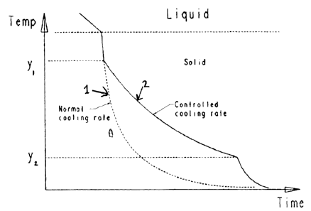
Fig. 1 shows a comparable example of producing a duplex stainless steel
strip by welding according to prior art having a normal cooling curve without
controlled cooling and an example of the invention comprising controlled
cooling as shown by the controlled cooling curve.
As it can be seen following the time line the interface section has an initial
temperature during the welding where it is at least partly in liquid phase.
According to the prior art method the interface section is allowed to cool (or
sometimes even subjected to a fast cooling). According to an embodiment of
the invention the interface section is allowed to cool to the temperature y,,
which may for example be about 900 C or about 1100 C, where after the
cooling rate is controlled so that the cooling is prolonged compared to what
it
would have been without the controlled cooling in particular in the
temperature interval y, - y2, where y2 e.g. may be about 600 C or about 300
C. The remaining cooling to the temperature of the environment may be
without cooling control.