Note: Descriptions are shown in the official language in which they were submitted.
CA 02682062 2009-10-09
BACKGROUND OF THE INVENTION
This invention concerns an antifreezing valve device for hydraulic and/or wa-
ter storage systems, particularly suitable for preventing freezing of water in
stor-
age systems of solar panels, in pipes, plants or valve devices for gardening
and
irrigation, in hydraulic plants of cold stores for food products, or, however
in any
hydraulic system exposed to freezing in which, due to potability requirements,
it is
not possible to add antifreeze liquids to the water.
STATE OF THE ART
In general, the use of antifreezing valves is known to protect hydraulic
and/or
io water storage systems from damages caused by the cold, the valves being con-
formed in such a way that, when the atmospheric temperature drops below a pre-
set value, they allow the water in the system to flow or to be discharged,
thereby
preventing the formation of ice which could cause breakage or cracks of the
sys-
tem itself.
Traditionally, an antifreezing valve of this kind comprises an extended valve
body which has a water inlet, connectable to a hydraulic and/or water storage
sys-
tem, and a water outlet, which open into an internal chamber for housing a
linear
thermostatic actuator.
The thermostatic actuator, which is slidably supported in the housing cham-
2o ber to be moved by a movable control rod of the same actuator in contrast
with a
first and a second coaxially arranged biasing springs, actuates a closing
member
in such a way as to move it from a closed position of the valve body inlet,
main-
tained for ambient temperatures equivalent to or higher than a preset value,
to an
open position for lower ambient temperatures, in which it discharges water.
CA 02682062 2009-10-09
2
However, these traditional antifreezing valves have reliability problems over
time, mainly related to the formation of encrustations and deposits on the
actuator
control rod and to the entry of dirt into the internal chamber of the valve
body
through the water outlet openings, with a consequent change in the
intervention
threshold of the valve, and with the possibility at worst that the valve could
be-
come blocked.
Also, from a constructional viewpoint, the configuration of the thermostatic
actuator and the relative contrast springs in these traditional antifreezing
valves
involves to adopt a valve body formed by several parts in order to allow the
as-
io sembling of the same valves, such a solution however entailing higher
production
and assembly costs.
Lastly, the coaxial positioning of the biasing springs involves high radial di-
mensions of the valve body, with consequent limitations in relation to the
installa-
tion possibilities of the valve.
Furthermore, with particular reference to plants for gardening and irrigation,
one or more delivering cocks are conventionally provided for delivering water,
which, together with the relevant pipes, can be damaged when the ambient tem-
perature goes down under 0 C, due to the freezing of the water remaining
therein.
Therefore a further need exists to suitably arrange an antifreezing valve in
20 such gardening and irrigation plants in order to protect both the
delivering cocks
and the relevant pipes from the risk of freezing.
OBJECTS OF THE INVENTION
The main object of this invention is to provide an antifreezing valve device
for
hydraulic and/or water storage systems, which is constructionally simple and
easy
CA 02682062 2009-10-09
3
to assemble, and which has a high degree of reliability over time, being
essentially
free from incrustation and dirt problems both on the thermostatic actuator
control
rod and in its housing chamber.
Another object is to provide an antifreezing valve device according to the in-
vention suitably associated with a fluid flow stop or adjusting valve device
con-
formed in such a way as to prevent freezing of water in the same stop or
adjusting
valve device and in the pipes to which it is connectable, when ambient tempera-
tures are equivalent or lower than a preset value.
BRIEF DESCRIPTION OF THE INVENTION
io The above may be achieved by an antifreezing valve device for hydraulic
and/or water storage systems, comprising:
a valve body having a water inlet, connectable to a hydraulic and/or water
storage system, the water inlet opening into an internal housing chamber for
hous-
ing a linear thermostatic actuator through a sealing seat, said valve body
having at
least one water outlet from said housing chamber;
a linear thermostatic actuator movably supported in said housing chamber,
said actuator having a cylindrical body from which a movable control rod
extends;
and
a closing member operatively connected to said thermostatic actuator, to be
20 moved from a closed position for closing said sealing seat for ambient
tempera-
tures equivalent to or higher than a preset value, to an open and water
discharg-
ing position for lower ambient temperatures,
wherein the closing member is conformed with a cup-shaped support ele-
ment sealingly slidable along the cylindrical body of the actuator, said cup-
shaped
CA 02682062 2009-10-09
4
element defining, with the actuator body, a closed chamber into which the
actuator
control rod extends to act against a bottom wall of the same cup-shaped
element,
wherein first biasing spring means are provided between one end of the
housing chamber and the closing member, and second biasing spring means are
provided between a second opposite end of the housing chamber and the linear
actuator, and
wherein guide means are provided for the linear actuator, respectively for the
closing member, axially sliding along internal walls of the housing chamber of
the
valve body.
io BRIEF DESCRIPTION OF THE DRAWINGS
These and further characteristics according to this invention will be more
clearly evident from the following description, with reference to the
accompanying
figures, in which:
Fig. 1 is longitudinal cross-sectional view of the antifreezing valve device
ac-
cording to this invention, with the closing member in the open position;
Fig. 2 is a further longitudinal cross-sectional view of the valve device in
Fig.
1, according to line 2-2, with the closing member in a closed position;
Fig. 3 is a cross-sectional view of an antifreezing valve device according to
this invention applied to a fluid flow stop or adjusting valve device of a
first type;
2o and
Fig. 4 is a cross-sectional view of an antifreezing valve device according to
this invention applied to a fluid flow stop or adjusting valve device of a
second
type.
DETAILED DESCRIPTION OF THE INVENTION
CA 02682062 2009-10-09
The general characteristics of this invention will be shown below through
several examples.
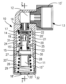
Figures 1 and 2 show an antifreezing valve device according to this inven-
tion, which is particularly suitable for installation on water storage systems
of solar
panels, or on water tanks in general, on pipes for gardening and irrigation,
on hy-
draulic systems of cold stores for food products, or on any other hydraulic
system
exposed to freezing which is connected to the water system and under pressure,
in order to prevent freezing of the water within them.
The valve device, indicated as a whole with reference number 10, comprises
io a valve body 11 extending along a longitudinal axis, the valve body 11
having at a
first front end a water inlet 12 connectable to a hydraulic and/or water
storage sys-
tem, not shown, by a suitable connector 13; in particular, in the
exemplificative
embodiment of Fig. 1, the water inlet 12 is in the form of a side opening at
the
aforementioned first end of the valve body 11, from which a connector 13
radially
extends, the connector 13 comprising a threaded connecting ring 13' internally
supported in order to be angularly rotatable and orientable according to its
own
axis.
The inlet 12 opens into an intemal housing chamber 14 inside valve body 11,
in which a linear thermostatic actuator 15 is arranged, such as a wax type
actua-
20 tor; the inlet 12 and the housing chamber 14 are connected to each other
through
an annular sealing seat 16 for a closing member 17 actuated by the linear
actua-
tor 15, as explained below.
As better illustrated in Fig. 2, the valve body 11 also has at least a water
out-
let opening for the outlet of water from the housing chamber 14, for example
an
CA 02682062 2009-10-09
6
axial opening 18' at a rear end of valve body 11 opposite to the inlet 12 and
a se-
ries of side openings 18" along the same valve body 11, such openings also al-
lowing the thermostatic actuator 15 to be exposed to the temperature of the
ambi-
ent air.
The thermostatic actuator 15, which, as specified further on, is movably sup-
ported in the housing chamber 14 by suitable guide means, has a cylindrical
body
15', and a movable control rod 19 extending from one end of the body 15', the
movable rod 19 being controlled by a temperature-sensitive wax bulb 15" ar-
ranged at the opposite end of the body 15' of actuator 15 itself.
io The aforementioned closing member 17 is operatively connected to the
thermostatic actuator 15 to be moved from an advanced closed position for clos-
ing the sealing seat 16 for ambient temperatures equivalent to or higher than
a
preset value, for example 4 C, to a retracted open position for discharging
water
for lower ambient temperatures, in order to prevent freezing of the water
present
in the system connected to the antifreezing valve device 10.
In particular, when the preset value of the ambient temperature is reached,
the closing member 17 is brought into the open position, allowing the water
pre-
sent in the pipe or in the tank to flow out; if, as normally happens, the
discharged
water is at a temperature higher than the ambient air, when it laps against
the
20 thermostatic actuator 15, it causes the closing member 17 to reclose,
stopping the
flow and exposing again the actuator 15 to the temperature of the ambient air.
Therefore, as long as the temperature of the discharged water remains
higher than the temperature of the ambient air, there is a sequence of
openings
and reclosings of the member 17, which limits the amount of water wasted while
CA 02682062 2009-10-09
7
still guaranteeing antifreeze protection of the system; if, on the other hand,
the
temperature of the discharge water and the ambient air are similar, the
closing
member 17 remains open, therefore discharging a constant flow of water which
prevents freezing of the water upstream.
According to this invention, the closing member 17 is conformed with a cup-
shaped support element 20 sealingly sliding along the cylindrical body 15' of
ac-
tuator 15, in such a way as to define with the body 15' of the actuator 15 a
closed
chamber 21 into which the control rod 19 of actuator 15 extends, thereby being
protected from incrustations and dirt.
In particular, the cup-shaped element 20 is slidable coaxially to the
cylindrical
body 15' and to the rod 19 of actuator 15, the rod 19 extending into the
closed
chamber 21 to an extent allowing the same rod to act against a bottom wall 20'
of
the cup-shaped element 20 itself, the bottom wall 20' having a disc gasket 22
for
sealingly closing the annular seat 16.
In order to form the necessary seal on the cylindrical body 15' of actuator
15,
the cup-shaped element 20 has an internal annular gasket 23 positioned in a
suit-
able annular housing slot.
The aforementioned advantageous configuration of the closing member 17
and the linear actuator 15 is also possible thanks to a new arrangement of the
2o necessary biasing spring means for the closing member 17 and the actuator
15 it-
self; in particular, the valve device 10 according to this invention comprises
first
biasing spring means, for example in the form of a first helical contrast
spring 24,
positioned between a first front end of housing chamber 14 and a first annular
shoulder 25 of the cup-shaped element 20 of the closing member 17, and second
CA 02682062 2009-10-09
8
biasing spring means, for example in the form of a second extra-stroke helical
spring 26, between the second opposite rear end of the housing chamber 14 and
a second annular shoulder of the linear actuator 15, consisting of an enlarged
body part 27 of the actuator itself.
The biasing spring means 24, 26 according to such configuration have lim-
ited radial dimensions which allow both to have sufficient space inside the
valve
body 11 for the aforementioned closed chamber 21 for the control rod 19, and
also to have a valve body 11 of reduced radial dimensions, with consequent
bene-
fits in terms of installation possibilities; also, since first spring 24 acts
directly on
to the closing member 17, biasing it to open, the danger of blocking of the
closing
member 17 itself, typical of traditional devices, is avoided.
The valve device 10 according to this invention also comprises, as said,
guide means for the linear actuator 15, for example in the form of a guide
ring 28,
which is inserted onto the sensitive bulb 15" and held against the enlarged
body
part 27 by the action of the second biasing spring 26; this guide ring 28 has
a pe-
ripheral edge conformed to axially slide along a first cylindrical wall 29
intemally
extending into the housing chamber 14, at the rear part of the valve body 11,
the
wall 29 ending on a front side with an annular stop surface 30 for the ring
28.
The valve device 10 also comprises guide means for the closing member 17,
20 for example defined by the annular shoulder 25 of the cup-shaped element
20,
which has a peripheral edge conformed to axially sliding along a second
cylindrical
wall 31 intemally extending into the housing chamber 14 at the front part of
valve
body 11.
In order to allow passage of the water between the iniet 12 and the outlets
CA 02682062 2009-10-09
9
18', 18", the guide ring 28 and the annular shoulder 25 have respective
passage
openings 28' and 25', for example provided along their peripheral edge, as
indi-
cated in Fig. 2.
In order to allow simplification of construction and assembly of the device,
the valve body 11 is preferentially formed in a single piece, for example by
hot
forming of brass, providing at a rear end an axial opening which may be
reclosed
by a suitable lid 32, attachable by screwing on or in another appropriate
manner,
in order to allow introduction of the actuator 15 and the closing member 17
inside
the valve body 11 itself; in this case, the axial outlet 18' for the water is
created on
io the lid 32.
Also, in order to prevent dirt and deposits from entering inside the chamber
14 of valve body 11, which could hinder the sliding movement of the
thermostatic
actuator 15 and of the closing member 17, the device 10 according to this
inven-
tion preferentially comprises suitable protection nets 33', 33", for example
in metal
material, at the outlet openings 18', 18" for the water, thereby achieving a
high
level of reliability over time.
In particular, in the embodiment shown, the protection net 33' for the axial
opening 18' is in the form of a disc-shaped net 33' inside lid 32, whereas the
pro-
tection net 33" for the side openings 18" is in the form of a tubular net 33"
in-
20 serted externally on valve body 11 and held in position between the lid 32
and a
shoulder part 34 on the valve body itself 11.
With reference to the mentioned problem of protecting gardening and irriga-
tion plants from the risk of water freezing, in Fig. 3, in which the same
reference
numbers have been used to indicate equivalent or similar parts, an
antifreezing
CA 02682062 2009-10-09
valve device according to this invention is illustrated, suitably applied to a
fluid flow
stop or adjusting valve device of a first type, for example in the form of a
ball cock.
The ball cock, indicated as a whole with reference number 35, comprises a
hollow body 36 having an inlet 37 and an outlet 38 for fluid which open into
an in-
ternal chamber 39 for housing a fluid flow stop and/or adjusting valve member,
in
this case in the form of a ball closing member 40, having an axial hole 40'
for pas-
sage of the fluid, as explained further on.
The hollow body 36 is preferentially formed of a first and a second body part
36', 36", connectable with each other through appropriate connecting means, in
io such a way as to make easy the assembly of the cock itself; in particular,
the first
body part 36' is conformed to have a cavity inside defining the housing
chamber
39, which is open on one side towards the fluid outlet 38, and on the opposite
side
towards a connector 41, internally threaded for connection of the second body
part 36", tubular in shape, which defines the fluid inlet 37.
Inside the housing chamber 39, there are a first and a second sealing annu-
lar seats 42, 43 for the ball closing member 40, which are provided on
separate
sealing rings, axially aligned with each other on opposite sides of the
chamber 39
at the inlet 37, respectively the outlet 38 for the water.
The ball closing member 40, which is positioned between these sealing seats
2o 42, 43 to be movably supported, has a rotatable control rod 44
perpendicular to
the axial hole 40' of the closing member 15, the rod sealingly extending
outside
the hollow body 36 through a hole 45 of the first body part 36', in a manner
to be
connected to a control knob, not shown, for the closing member.
In particular, since the control rod 44 is sealingly inserted in the hole 45
with
CA 02682062 2009-10-09
11
the possibility of rotating around its own axis, the closing member 40 is
angularly
movable according to the axis of control rod 44, to be rotated between a first
an-
gular open position, in which the passage hole 40' in the closing member 40 is
axially aligned with inlet 37 and outlet 38, and a second angular closing
position,
rotated of 90 with respect to the previous one, in which the closing member
40
closes the flow, by interacting with the sealing seat 43 towards the fluid
outlet 38.
In order to protect the ball cock from the risk of freezing, the housing cham-
ber 39 of the closing member 40 has a fluid discharge opening 46 communicating
with the outside through a thermostatic anti-freeze valve 10 according to the
in-
lo vention, the features of which are described above, in a manner to cause
dis-
charge and/or flow towards the outside of the water remaining in the housing
chamber 39 and upstream of it, when the cock 35 is closed, for ambient tempera-
tures lower than a preset value, for example 4 C.
Preferentially, the discharge opening 46 is made in the first body part 36' on
a lower side of the housing chamber 39 opposite to the control rod 44, in a
man-
ner to allow, in the case of low ambient temperatures, an efficient flow
towards the
outside of the water present in chamber 39 itself and in the axial hole 40',
which,
in the closing position of the closing member 40, is freely communicating with
the
housing chamber 39.
20 In order to allow the water present upstream to the housing chamber 39 to
flow and be discharged in the case of low ambient temperatures, with
particular
reference to the water present at the inlet 37, in the second body part 36",
and in
the pipes, not shown, to which cock 35 is connectable, the ball closing member
40
includes a through connecting opening 47 which, in the closing position of the
CA 02682062 2009-10-09
12
closing member 40, extends transversally between an intemal side wall of axial
hole 40' and the external surface of closing member 40 facing towards the
inlet
37, thereby placing in communication the zone of inlet 37 with the axial hole
40' in
the closing member 40 and therefore with the discharge opening 46.
Preferentially, the first body part 36' at the discharge opening 46 has a
threaded connector 48 for connection of the thermostatic anti-freeze valve 10;
it is
possible for the body of the anti-freeze valve to be manufactured as a single
piece
with the body 36 of the cock 35.
From the above, it is clear that the ball cock 35 provided with the anti-
freeze
io valve 10 according to the invention allows efficient flowing and/or
discharge of the
water present in the cock itself, and also in the pipes to which it is
connected,
when the closed cock is exposed to ambient temperatures close to or lower than
0 C, thereby preventing freezing of the water.
In Fig. 4, in which the same reference numbers have been used to indicate
equivalent or similar parts, an antifreezing valve device according to this
invention
is illustrated, suitably applied to a second type of fluid flow stop or
adjusting valve
device, for example in the form of a cock having a disk shaped closing member.
The disk cock, indicated as a whole with reference number 49, comprises a
hollow body 50 having an inlet 51 and an outlet 52 for fluid which open into
an in-
20 ternal chamber 53 for housing a fluid flow stop and/or adjusting valve
member, in
this case in the form of a disk shaped closing member 54, which is axially
movable
by a rotatable control rod 55 to interact with an annular sealing seat 56,
coaxially
arranged to the disk closing member 54.
In order to protect the disk cock 49 and the relevant pipes upstream to the
CA 02682062 2009-10-09
13
same cock from the risk of freezing, the housing chamber 53 for the closing
mem-
ber 54 has a fluid discharge opening 57 provided at the bottom part of the
body
50, the opening 57 communicating with the outside through a thermostatic anti-
freeze valve 10 according to the invention.
Preferentially, the hollow body 50 at the discharge opening 57 has a
threaded connector 58 for connection of the thermostatic anti-freeze valve 10.
What is stated and shown with reference to the accompanying drawings has
been provided simply by way of example and to illustrate the general
characteris-
tics of the invention and also preferential embodiments; therefore, other
modifica-
lo tions and variations to the antifreezing valve for hydraulic and/or water
storage
systems are possible, without thereby deviating from the claims.