Note: Descriptions are shown in the official language in which they were submitted.
CA 02682124 2009-09-25
WO 2008/129015
PCT/EP2008/054768
INTEGRALLY BLOW-MOULDED BAG-IN-CONTAINER HAVING A BAG
ANCHORING PONT; PROCESS FOR THE PRODUCTION THEREOF;
AND TOOL THEREFOR
Field of the Invention
The present invention relates in general to new developments in dispensing
bag-in-containers and, in particular, to anchoring means for fixing the bag to
the
container at at least one point in order to stabilize it during collapse
thereof upon use.
It also relates to a method and tool for producing said bag-in-containers.
Background of the Invention
Bag-in-containers, also referred to as bag-in-bottles or bag-in-boxes
depending
on the geometry of the outer vessel, all terms considered herein as being
comprised
within the meaning of the term bag-in-container, are a family of liquid
dispensing
packaging consisting of an outer container comprising an opening to the
atmosphere -
- the mouth -- and which contains a collapsible inner bag joined to said
container and
opening to the atmosphere at the region of said mouth. The system must
comprise at
least one vent fluidly connecting the atmosphere to the region between the
inner bag
and the outer container in order to control the pressure in said region to
squeeze the
inner bag and thus dispense the liquid contained therein.
Traditionally, bag-in-containers were --and still are-- produced by
independently producing an inner bag provided with a specific neck closure
assembly
and a structural container (usually in the form of a bottle). The bag is
inserted into the
fully formed bottle opening and fixed thereto by means of the neck closure
assembly,
which comprises one opening to the interior of the bag and vents fluidly
connecting
the space between bag and bottle to the atmosphere; examples of such
constructions
can be found inter alia in U5A3484011, U5A3450254, USA4,330,066, and USA-
4892230. These types of bag-in-containers have the advantage of being
reusable, but
they are very expensive and labour-intensive to produce.
1
CA 02682124 2009-09-25
WO 2008/129015
PCT/EP2008/054768
More recent developments focused on the production of "integrally blow-
moulded bag-in-containers" thus avoiding the labour-intensive step of
assembling the
bag into the container, by blow-moulding a polymeric multilayer preform into a
container comprising an inner layer and an outer layer, such that the adhesion
between
the inner and the outer layers of the thus produced container is sufficiently
weak to
readily delaminate upon introduction of a gas at the interface. The "inner
layer" and
"outer layer" may each consist of a single layer or a plurality of layers, but
can in any
case readily be identified, at least upon delamination. Said technology
involves many
challenges and many alternative solutions were proposed.
The multilayer preform may be extruded or injection moulded (cf. USA-
6238201, JPA10128833, JPA11010719, JPA9208688, U5A6649121. When the
former method is advantageous in terms of productivity, the latter is
preferable when
wall thickness accuracy is required, typically in containers for dispensing
beverage.
Preforms for the production of integrally blow-moulded bag-in-containers
clearly differ from preforms for the production of blow-moulded co-layered
containers, wherein the various layers of the container are not meant to
delaminate, in
the thickness of the layers. A bag-in-container is comprised of an outer
structural
envelope containing a flexible, collapsible bag. It follows that the outer
layer of the
container is substantially thicker than the inner bag. This same relationship
can of
course be found in the preform as well, which are characterized by an inner
layer
being substantially thinner than the outer layer. Moreover, in some cases, the
preform
already comprised vents which are never present in preforms for the production
of co-
layered containers (cf. EPA1356915).
The formation of the vents fluidly connecting the space or interface between
bag and bottle to the atmosphere remains a critical step in integrally blow-
moulded
bag-in-containers and several solutions were proposed in e.g., USA5301838, USA-
5407629, JPA5213373, JPA8001761, EPA1356915, U5A6649121, JPA10180853.
One redundant problem with integrally blow-moulded bag-in-containers is the
choice
2
CA 02682124 2009-09-25
WO 2008/129015
PCT/EP2008/054768
of materials for the inner and outer layers which must be selected according
to strict
criteria of compatibility in terms of processing on the one hand and, on the
other hand,
of incompatibility in terms of adhesion. These criteria are sometimes
difficult to fulfil
in combination as illustrated below. The thermal properties of the materials
of the
inner and outer layers should be as close as possible for the blow-moulding
step, but
should differ sufficiently for the injection moulding production of an
integral
multilayer preform.
Beside the thermal properties, it should be ensured that the inner and outer
layers form a weak interface to ensure proper delamination of the inner layer
from the
outer layer upon use; JP2005047172 states that the inner and outer layers
should be
made of "mutually non-adhesive synthetic resins."
As an interface between inner and outer layer is inevitably formed upon blow-
moulding, which strength may not always be as uniform as one could desire, due
to
various phenomena during the blow-moulding stage, such as local heat
gradients,
differential resin stretch and flow rates at different points of the vessel,
etc., the
delamination of the inner bag from the outer layer is not always perfectly
controllable.
It has been observed that the two layers may delaminate preferentially on one
side of
the bag-in-container due to a local weakness of the interface and, as the bag
starts shrinking asymmetrically bending and folding with the risk of forming
pockets full of liquid separated from the container's mouth. If this happens,
the bag-
in-container cannot be used anymore although it can still contain a
considerable
amount of liquid.
JP4267727 suggests to fix the inner and outer layers at their bottoms without
disclosing how to achieve this. In Japanese Utility Model JP7048519, one end
of a
co-extruded multilayer parison is pinched off such that mutually engaging
corrugations are formed, and fixing the structure through an additional device
prior to
blow-moulding. USA6649121 proposes to fix the inner bag to the outer layer by
3
CA 02682124 2009-09-25
WO 2008/129015
PCT/EP2008/054768
forming at the bottom of the inner layer of the preform to be blow-moulded
into the
bag-in-container, a protrusion which fits a through hole formed at the bottom
of the
outer layer and engages mechanically on the outer surface of the outer layer.
This geometry appears to be maintained through the blow-moulding process by
limiting the axial stretch of the bottom area of the container through the
driving
downwards of a stretching rod.
Co-extruded parisons as described in the foregoing Japanese Utility Model do
not allow the same wall thickness control as when injection moulded preforms
are
used, which is required in applications in the field of pressurized beverage
dispense
bag-in-containers. The solution proposed in USA6649121 applies to bag-in-
containers wherein the liquid contained in the bag is dispensed by decreasing
the
pressure in the bag and does not allow to dispense liquid by injection of a
pressurized
gas at a point of the interface between the inner and outer layers because the
inner
layer's protrusion is not meant to engage hermetically on the outer surface of
the outer
layer. Indeed, the solution proposed in USA6649121 includes that air must
penetrate
through the interstice between the protrusion and the through hole wall to
compensate
for the growing pressure drop as a gap is formed between the inner and outer
layers
upon extracting the liquid by vacuum and the resulting shrinking of the bag.
It follows from the foregoing that there remains a need in the art for an
integrally blow-moulded bag-in-container that allows controlled delamination
of the
inner bag from the outer container upon injection of a pressurized gas at the
interface
thereof
Summary of the Invention
The present invention is defined in the appended independent claims.
Preferred embodiments are defined in the dependent claims. In particular the
present
4
CA 02682124 2009-09-25
WO 2008/129015
PCT/EP2008/054768
invention relates to an integrally blow-moulded bag-in-container obtainable by
blow-
moulding an injection moulded multi-layer preform. The bag-in-container
includes an
inner layer forming the bag and an outer layer forming the container, and a
single
opening, the mouth, fluidly connecting the volume defined by the bag to the
atmosphere. The container further includes at least one interface vent fluidly
connecting the interface between inner and outer layers to the atmosphere,
wherein
the bag is anchored to the outer layer at at least one point remote from the
single
opening.
It also concerns a process for producing a bag-in-container as described above
comprising the following steps:
= providing a polymer preform comprising two layers;
= bringing the preform to blow-moulding temperature;
= blow-moulding the thus heated preform to form a bag-in-container;
wherein during the process, the inner bag is anchored to the outer layer at at
least one
point remote from the bag-in-container's mouth.
The anchoring may be realized through locally enhanced mechanical, physical,
or chemical adhesion between the inner and outer layers, or combinations
thereof
Locally enhanced mechanical adhesion may be provided with a blow-
moulding tool comprising for example a sump or depression in which inner and
outer
layers engage during the blow-moulding process and thus become interlocked.
The sump or depression may be provided in the blow-moulding tool by
5
CA 02682124 2009-09-25
WO 2008/129015
PCT/EP2008/054768
inserting therein a chime defining said sump or depression. When effecting the
blow-
moulding operation with the chime incorporated in the blow-moulding tool the
interlocking between the inner and outer layers is achieved and additionally
the chime
is readily fixed to the container.
Brief Description of the Drawings
Figure lA is a schematic cross-sectional representation of a first embodiment
of a preform according to the present invention and the bag-in-container
obtained
after blow-moulding thereof
Figure 1B: is a schematic cross-sectional representation of a second
embodiment of a preform according to the present invention and the bag-in-
container
obtained after blow-moulding thereof.
Figure 2: is a schematic representation of a blow-moulding tool with a bag-in-
container therein.
Detailed Description of the Invention
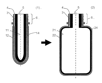
Referring now to appended Figures lA and 1B, there is illustrated an
integrally blow-moulded bag-in-container (2) and a preform (1)&(1') for
its manufacturing. The preform (1) comprises an inner layer (11) and an outer
layer
(12) joined at least at the level of the neck region (6) by an interface
(shown on the
right hand side). The region between inner and outer layers (11) and (12) may
either
consist of an interface (14) wherein the two layers are substantially
contacting each
other, or comprise a gap (14') in fluid communication with at least one vent
(3). Said
vent (3) comprises an opening to the atmosphere in (4).
Many vent geometries have been disclosed and it is not critical which
geometry is selected. It is preferred, however, that the vent be located
adjacent to, and
oriented coaxially with said preform's mouth (5) as illustrated in Figure 1.
More
preferably, the vents have the shape of a wedge with the broad side at the
level of the
opening (4) thereof and getting thinner as it penetrates deeper into the
vessel, until the
two layers meet to form an interface (14) at least at the level of the neck
region.
6
CA 02682124 2009-09-25
WO 2008/129015
PCT/EP2008/054768
This geometry allows for a more efficient and reproducible delamination of the
inner
bag upon use of the bag-in-container. The container may comprise one or
several
vents evenly distributed around the lip of the bag-in-container's mouth.
Several
vents are advantageous as they permit the interface of the inner and outer
layers (21)
and (22) of the bag-in-container (2) to release more evenly upon blowing
pressurized
gas through said vents. Preferably, the preform comprises two vents opening at
the
vessel's mouth lip at diametrically opposed positions. More preferably, three,
and
most preferably, at least four vents open at regular intervals of the mouth
lip.
The preform may consists of an assembly of two independent injection
moulded preforms (11) and (12) produced independently from one another and
thereafter assembled such that the inner preform (11) fits into the outer
preform (12).
This solution allows for greater freedom in the design of the neck and vents,
as well
as in the choice of materials constituting each preform component.
Alternatively, it
can be an integral preform obtained by injection moulding one layer on top of
the
other. The latter embodiment is advantageous over the assembled preform in
that it
comprises no assembly step and one production station only is required for the
preform fabrication. On the other hand, the design of the vents in particular
is restricted and the respective melting temperatures of the inner and outer
layers must
be carefully matched depending on which layer is injected first; the rule of
thumb
being that the layer being injected first generally requires a higher melting
temperature.
The inner and outer layers of the preform (1) may consist of different
materials or the same material. In
case different materials are used, some
requirements must be fulfilled depending on the process parameters in the
injection
moulding of the preform as well as in the blow-moulding of the bag-in-
container. It
is important of course that both materials may be processed in a rather
similar process
window and that they will not form too strong an interface which would not
satisfactorily release upon injecting pressurized gas at the interface.
7
CA 02682124 2015-06-11
CA 02682124 2009-09-25
WO 2008/129015
PCT/EP2008/054768
Alternatively and surprisingly, good results can be obtained also with
preforms wherein both inner and outer layers consist of the same material.
Particularly in case of integral, over-moulded preforms, it is generally
believed that
better results are obtained with semi-crystalline polymers.
The same polymer is considered in contact on either side of the interface
between the inner and outer layers in the following cases:
= inner and outer layers consist of the same material (e.g..
PETinmerPETautcr, regardless of the specific grade of each PET); or
= the inner and outer layers consist of a blend or copolymer
having at least one polymer in common, provided said polymer in common
is at the interface, whilst the differing polymer is substantially absent of
said
interface (e.g., (0.85 PET+0.15 PA6)ina.40.8 PET+0.2 PE)outer.
The presence in a layer of low amounts of additives is not regarded as
rendering the
material different, so far as they do not alter the interface substantially.
Preferred materials for the preform and bag-in-container of the present
invention are polyesters like PET, PEN, P11, PTN; polyamides like PA6, PA66,
PA11, PA12; polyolefins like PE, PP; EVOH; biodegradable polymers like
polyglycol
acetate (PGAc), Polylactic acid (PLA); and copolymers and blends thereof. In
case
different materials are used for the inner and outer layers, their optimal
blow-
moulding temperature should not differ from one another by more than 70 C,
preferably 40 C, most preferably 10 C, and ideally should have the same blow-
moulding temperature.
The two layers (11) and (12) of the preform may be connected by an interface
(14) throughout substantially the whole inner surface of the outer layer.
Inversely,
they may be separated over a substantial area of the preform's body by a gap
(14')
8
CA 02682124 2015-06-11
wo 2008/129015 PCT/EP2008/054768
containing air and which is in fluid communication with at least one interface
vent (3).
The latter embodiment is easier to realize when using a preform assembly
designed
such that the inner preform is firmly fixed to the outer preform at the neck
region (6)
and a substantial gap (141 may thus be formed between inner and outer layers
(11) and
(12).
The bag-in-container (2) of the present invention is obtained by providing a
preform as described above; bringing the inner and outer layers of said
preform to
blow-moulding temperature; fixing the thus heated preform at the level of the
neck
region with fixing means in the blow-moulding tool; and blow-moulding the thus
heated preform to form a bag-in-container, such that the inner layer is
locally
anchored to the outer layer at a location remote from the bag-in-
container's neck
region.
The inner and outer layers (21) and (22) of the thus obtained bag-in-container
are connected to one another by an interface (24) over substantially the whole
of the
inner surface of the outer layer. Said interface (24) is in fluid
communication with the
atmosphere through the vents (3), which maintained their original geometry
through
the blow-moulding process since the neck region of the preform where the vents
are
located is held firm by the fixing means and is not stretched during blowing.
It is essential that the interface (24) between inner and outer layers (21)
and
(22) releases upon blowing pressurized gas through the vents in a consistent
and
reproducible manner. The success of said operation depends on a number of
parameters, in particular, on the interfacial adhesive strength, the number,
geometry,
and distribution of the vents, the pressure of the gas injected, and the inner
bag
stability. The latter can be substantially improved by fixing the inner layer
to the
outer layer at a location remote from the neck region and mouth of the bag-in-
container, such that the interface between inner and outer layers will not
release at
said anchoring point upon injecting pressurized gas at a point of the
interface. The
bag is thus fixed at two points remote from one another: the neck region and
the
9
CA 02682124 2015-06-11
CA 02682124 2009-09-25
WO 2008/129015 PCT/EP2008/054768
anchoring point. This allows to better control the collapse of the bag, which
is
essential for a reliable and reproducible operation of the bag-in-container.
The anchoring of the inner to the outer layers may be provided by a locally
enhanced mechanical, physical. or physical adhesion. Mechanical adhesion
includes any interaction between inner and outer layers at all scales spanning
from
macroscopic mechanical interlocking to cross-crystallinity as well as
molecular inter-
diffusion across the interface, all phenomena well known to the person skilled
in the
art. Physical and chemical adhesion is also well studied and involves
dispersive
forces (e.g., London and Keaton forces), acid base interactions (sometimes
also
referred to as polar forces), hydrogen bonds, and covalent bonds.
All, but macroscopic interlocking, of the above adhesion mechanisms are
temperature dependent and may be locally promoted, e.g., by controlling the
local
temperature of the interface at the point where anchoring is desired. In case
of
preform assemblies, an adhesive may be applied at the desired anchoring point
prior
to fitting the inner preform into the outer one. The adhesive must resist the
blow-
moulding temperature and be compliant enough to stretch with the preform upon
blowing.
Macroscopic interlocking may be achieved by using a blow-moulding tool
comprising a sump or depression at the desired anchoring point, preferably at
the
bottom of the container as illustrated in Figure I, Upon blow-moulding the
heated
preform expands and the inner and outer layers engage into the sump. The
angle,
formed by the sump wall with the surrounding container's body wall maybe
greater to
or equal to 90 degrees, in which case an anchoring point is formed by enhanced
friction between the inner and outer layer at the level of the thus produced
protrusion
or, alternatively, the angle can be smaller than 90 degrees, in which case a
mechanical
interlocking of the two layers is formed like a rivet.
CA 02682124 2009-09-25
WO 2008/129015
PCT/EP2008/054768
Preferably a stretching rod drives the preform downwards during the blow-
moulding process to promote longitudinal stretching and to ensure that good
contact
of the preform with the tool's wall is effected at the desired point of
anchoring.
In the case the angle, a, formed by the sump wall with the surrounding
container's
body wall is smaller than 90 degrees and the mechanical interlocking of the
two layers
is formed like a rivet, the anchoring point comprises an undercut. The
creation of this
undercut can be achieved in several methods, some of which are described
below.
According to a first method, the undercut is created by using a blow-moulding
tool
comprising two half-moulds that are only partially closed at the location of
the sump,
the side walls of the half-moulds at the sump location defining a negative of
the
anchoring point to be created. The preform is driven down in the sump by means
of a
stretching rod, where after both half-moulds are moved towards each other to
entirely
close the mould, creating the undercut.
According to another method, a blow-moulding tool is used comprising axially
moving pins that can be introduced in the mould cavity during blow-moulding,
allowing creation of the undercut.
According to yet another method, the blow-moulding tool with half-moulds
defining a
sump negative to the anchoring point to be created. The preform beind driven
into the
sump by means of the fluid pressure applied during blow-moulding thereof. In
this
method, a stretching rod may be used that either stops at a position distant
from the
sump or that extends into the sump. In the last case, it is preferred to use a
stretching
rod provided with a central fluid channel and lateral openings at its distal
end (the end
extending in the blow-moulding tool) that extends into the sump during
stretching,
such that part of the fluid used to stretch the preform is guided through the
fluid
channel and the lateral openings to facilitate stretching of the preform into
the sump
and against the inner wall the mould cavity defining the sump.
Figure 2 schematically represents a blow-moulding tool with provided therein a
chime
comprising said sump or depression at the desired anchoring point. This chime
is
inserted in the blow-moulding tool prior to blow-moulding the preform, such
that
11
CA 02682124 2015-06-11
wo 2008/129015 PCT/EP2008/054768
upon blow moulding the heated preform expands and the inner and outer
layers engage into the sump. In this manner, the desired macroscopic
interlocking is
achieved and additionally a chime is provided on the container. In the case
the sump
defined by the chime is designed for the creation of an anchoring point in the
form of
a rivet, the anchoring point can successfully be created by means of fluid
pressure
forcing the material of the preform into the sump. Both methods applying a
stretching
rod and not applying a stretching rod can be used.
A release agent may be applied at the interface on either or both surfaces of
the inner and outer layer, which are to form the interface of the bag-in-
container. In
the case the outer layer is injection moulded onto the inner layer, the
release agent can
be applied at the outer surface of the inner layer prior to moulding the outer
layer.
Any release agents available on the market and best adapted to the material
used for
the preform and resisting the blowing temperatures, like silicon- or PTFE-
based
release agents (e.g., Freekote ) may be used. The release agent may be applied
just
prior to loading the preforms into the blowmoulding unit, or the preforms may
be
supplied pretreated.
The application of a release agent is particularly beneficial with respect to
the
design of the inner layer. Indeed, lowering the interferential adhesive
strength
facilitates delamination of the inner layer from the outer layer and hence
reduces
stress exerted on the inner layer upon delamination, as such the inner layer
can be
designed very thin and flexible without risking that the inner layer is
damaged upon
delamination. Clearly, the flexibility of the inner bag is a key parameter for
the liquid
dispensing and moreover costs savings can be achieved in temis on material
savings
when the inner layer can be designed very thin.
12