Note: Descriptions are shown in the official language in which they were submitted.
CA 02682181 2009-09-18
WO 2008/121538 PCT/US2008/057089
TITLE
MEANS FOR SECURING A TRANSPORT BASE
TO A SHIPPING PALLET
BACKGROUND
Field Of The Invention
This patent relates to a palletized packaging assembly. More
particularly, this patent relates to a packaging assembly in which the outer
carton and the manufacturing transport base are secured to the shipping
pallet to prevent lateral movement of the packaged article relative to the
shipping pallet.
Description Of The Related Art
Articles such as outside air conditioners or large household appliances
(washers, dryers, ranges, etc.) are often carried along assembly lines on
transport bases made of corrugated fiberboard, honeycomb, foam or a
combination of these materials. When these units are boxed and placed on
shipping pallets (skids), they tend to shift, causing the boxed article to
overhang the edges of the shipping pallet, sometimes resulting in damage to
the packaged article and/or stacking and handling difficulties.
Thus the primary object of the present invention is to provide a
packaging system that prevents a boxed article from the shifting with respect
to the shipping pallet on which it rests.
Another object of the invention is to provide a shipping package in
CA 02682181 2009-09-18
WO 2008/121538 PCT/US2008/057089
2
which the manufacturing transport base and outer box or carton are secured
to the shipping pallet to prevent shifting of the product on the shipping
pallet.
Further and additional objects will appear from the description,
accompanying drawings, and appended claims.
CA 02682181 2009-09-18
WO 2008/121538 PCT/US2008/057089
3
SUMMARY OF THE INVENTION
The present invention is unitary palletized assembly for packaging an
article in which a manufacturing transport base and an outer carton are
removably secured to a shipping pallet to prevent movement of the packaged
article with respect to the shipping pallet in any lateral (horizontal)
direction.
The packaging assembly comprises three main components: a shipping
pallet, typically made of wood, a composite manufacturing transport base
that rests on the pallet, and an open bottom carton that surrounds and
protects the sides and top of the packaged article. Corner posts may be
inserted inside the carton between the carton and the packaged article for
lateral impact protection and axial strength. The article to be packaged can
be any large article, such as an air conditioning unit or a large household
appliance.
The shipping pallet has a load bearing surface, typically defined by a
plurality of parallel cross members, which are themselves supported by two
parallel runners. Elongated front and rear stops are affixed to opposing ends
of the shipping pallet. The carton and transport base are wedged between the
front and rear stops to prevent lateral movement of the packaged article in
two directions (forward and rearward).
The transport base is substantially rectangular and comprises a bottom
panel having a perimeter defined by first and second sets of opposing fold
lines, front and rear panels hingedly attached to the bottom panel along one
CA 02682181 2009-09-18
WO 2008/121538 PCT/US2008/057089
4
set of opposing fold lines, and side panels hingedly attached to the bottom
panel along the other set of opposing fold lines. A plurality of load bearing
cushioning elements are arranged in spaced relation near the perimeter of the
bottom panel for supporting and cushioning the packaged article. The front
and rear panels are folded upward and inward to at least partially encapsulate
the cushioning elements.
The carton, when placed over the article and transport base, encloses
the four sides of the transport base and extends upwardly therefrom. The
carton comprises four side walls, four top flaps and four relatively narrower
bottom flaps. The bottom flaps consist of front and rear flaps and two side
flaps and are narrower than the top flaps.
In the assembled package the carton front and rear flaps are folded or
tucked under the transport base and are interposed between the transport base
and the shipping pallet during shipping. The carton side flaps extend
downward, over the transport base side panels, and are secured to the
shipping pallet runners by staples or other attachment means, with the
transport base side flaps sandwiched and secured therebetween.
The assembled package is referred to as "unitary" because the carton,
manufacturing transport base and shipping pallet are secured together to
form a stable unit.
CA 02682181 2009-09-18
WO 2008/121538 PCT/US2008/057089
THE DRAWINGS
Figure 1 is an exploded view of a unitary palletized packaging
assembly according to the present invention.
Figure 2 is a perspective view of a shipping pallet which forms part of
5 the unitary packaging assembly of Figure 1.
Figure 3 is a partial close up view of the shipping pallet of Figure 2.
Figure 4 is a perspective view of a transport base which forms part of
the unitary packaging assembly of Figure 1.
Figure 5 is another perspective view of the transport base of Figure 4.
Figure 6 is a perspective view of the transport base of Figure 4 shown
resting on the shipping pallet of Figure 2.
Figure 7 is a partial close up view of the transport base and shipping
pallet of Figure 6.
Figure 8 is a perspective view of a carton which forms part of the
unitary packaging assembly of Figure 1.
Figure 9 is a partial close up view of the carton and transport base of
Figures 4 and 8 being placed onto the shipping pallet of Figure 2.
Figure 10 is a partial close up view of the carton and transport base
resting on the shipping pallet.
Figure 11 is another partial close up view of the carton and transport
base resting on the shipping pallet.
CA 02682181 2009-09-18
WO 2008/121538 PCT/US2008/057089
6
Figure 12 is still another partial close up view of the carton and
transport base resting on the shipping pallet, shown with a carton bottom flap
and transport base side flange folded downward and stapled to the side of the
shipping pallet.
Figure 13 is an interior view of the assembled carton, transport base
and shipping pallet of Figure 12, shown without the packaged article or
interior corner posts.
CA 02682181 2009-09-18
WO 2008/121538 PCT/US2008/057089
7
DETAILED DESCRIPTION OF THE INVENTION
While this invention may be embodied in many forms, there is shown
in the drawings and will herein be described in detail one or more
embodiments, with the understanding that this disclosure is to be considered
an exemplification of the principles of the invention and is not intended to
limit the invention to the illustrated embodiment(s). Although the invention
will now be described as a packaging assembly for an air conditioner, it
should be understood that the invention can be used to package other
articles, including but not limited to large household appliances.
Turning to the drawings, there is shown in Figure 1 an exploded view
of one embodiment of the present invention, a unitary palletized packaging
assembly 10 in which a carton 32 and manufacturing transport base 18 are
secured to a shipping pallet 12 to prevent lateral (horizontal) movement of
the packaged article 50 with respect to the shipping pallet 12. The packaging
assembly 10 comprises three main components: the shipping pallet 12,
typically made of wood, a composite manufacturing transport base 18 that
rests on the pallet 12, and an open bottom carton 32 that is placed over the
article 50 and transport base 18 while or after the article is assembled.
Optional corner posts 17 may be inserted between the carton 32 and the
packaged article 50 for protecting the article 50 from impact forces and
providing axial compression strength to the overall package 10. Other
optional components include corner post caps 19 mounted to the top ends of
CA 02682181 2009-09-18
WO 2008/121538 PCT/US2008/057089
8
the corner posts 17 and a top frame 21, both of which are the subject of a co-
pending and co-owned patent application.
The article 50 to be packaged can be any large article, such as the air
conditioning unit depicted in Figure 1. The article 50 typically rests on the
transport base 18 during manufacture, with the transport base 18 ultimately
functioning as the bottom of the carton 32. By wedging the carton 32 and
transport base 18 between two opposing end stops 16 which form part of the
shipping pallet 12, and by securing the carton side bottom flaps 38 and
transport base side panels 28 to the sides of the shipping pallet 12, the
packaged article cannot move laterally relative to the shipping pallet 12.
As shown in Figures 2 and 3, the shipping pallet 12 comprises a load
bearing surface defined by a plurality of load bearing cross members 14
arranged in parallel and secured at opposing to parallel side runners 15. The
basic shipping pallet 12 may be modified as shown by affixing to the
opposing front and rear ends of the shipping pallet 12 parallel, elongated,
spaced apart front and rear stops 16. The front and rear stops 16 may be
attached to the side runners 15 either directly, as shown in Figure 3, or
indirectly by being attached to the load bearing cross members 14. Further,
the front and rear stops 16 may be oriented perpendicular to the runners 15 as
shown in the figures or parallel thereto.
As explained below, the front and rear stops 16 help prevent forward
or rearward movement of the carton 32 and transport base 18 relative to the
CA 02682181 2009-09-18
WO 2008/121538 PCT/US2008/057089
9
shipping pallet 12. The shipping pallet may be made from wood or any other
suitable material. Preferably the load bearing surface is raised off the
ground
to enable the packaging assembly 10 to be moved with a fork lift truck.
Referring now to Figures 4 and 5, the transport base 18 that serves as
the bottom of the carton 32 and rests on the shipping pallet 12 comprises a
flat (planar) bottom pane120 having a perimeter defined by first and second
sets of opposing fold lines 24, 22, front and rear panels 26 hingedly attached
to the bottom pane120 along the second set of opposing fold lines 22, side
panels 28 hingedly attached to the bottom pane120 along the first set of
opposing fold lines 24, and two or more load bearing cushioning elements 30
arranged in spaced relation near the perimeter of and affixed to the bottom
pane120.
The cushioning elements 30 may be positioned in any suitable
locations on the bottom pane120, but preferably they are spaced around the
perimeter of the bottom panel near the corners so that the article 50 rests on
the encapsulated cushioning elements 30. In the embodiment illustrated in
the figures two cushioning elements 30 are placed at each corner of the
bottom pane120 for a total of eight cushioning elements 30. Each pair of
cushioning elements 30 at each corner are positioned at right angles to each
other alongside adjoining orthogonal fold lines 22, 24 and are spaced away
from their mutual corner in order to leave space to accommodate corner posts
17.
CA 02682181 2009-09-18
WO 2008/121538 PCT/US2008/057089
Still referring to Figures 4 and 5, the front and rear panels 26 are
configured to partially encapsulate the cushioning elements 30 by folding
each front and rear pane126 up and over the cushioning elements 30.
Specifically, each front and rear pane126 comprises a side wa1127 foldably
5 connected to the transport base bottom pane120 along first fold line 22 and
a
top wa1129 connected to the side wa1127 along a third fold line 25. In order
to encapsulate the cushioning elements 30, the front and rear panels 26 are
folded upward along second fold lines 22 at a ninety degree angle and then
inward (toward each other) along third fold lines 25 at a ninety degree angle
10 to cover at least a portion of the outer facing sides and tops of the
cushioning
elements 30. The side walls 27 and top walls 29 may be glued or otherwise
affixed to the sides and tops of the cushioning elements 30. As shown in the
figures, the top walls 29 are substantially U-shaped to at least partially
encapsulate (cover) all eight cushioning elements 30, and are beveled (cut at
an angle relative to the corners of the transport base 18) to accommodate the
corner posts 17.
Referring to Figures 1 and 8, the shipping carton 32 comprises four
vertical side walls 34, top flaps 40 and four relatively narrow bottom flaps
36, 38. The bottom flaps 36, 38 comprise front and rear flaps 36 and side
flaps 3 8 and do not function as the carton bottom, at least not by
themselves.
Rather, as explained below, the carton front and rear flaps 36 cooperate with
the transport base 18 to form the carton bottom. More specifically, in the
CA 02682181 2009-09-18
WO 2008/121538 PCT/US2008/057089
11
assembled packaging unit 10, the carton front and rear flaps 36 are tucked
under the transport base 18 between the transport base 18 and the shipping
pallet 12 (see Figures 9 and 11) while the side flaps 38 extend downward in
roughly the same plane as the carton side walls 34 and are stapled to the
pallet runners 15 (see Figure 12).
The corner posts 17 shown in Figure 1 are disposed within the carton
32 adjacent the inner corners of the carton 32 to provide for corner impact
protection and axial strength. The corner posts 17 can be conventional
corner posts of the type manufactured and marketed by Sonoco Products
Company of Hartsville, South Carolina. However, any suitable support
structures may be used for corner impact protection and axial strength,
including without limitation angle board.
The unitary palletized packaging assembly 10 of the present invention
may be assembled and used in the following manner.
First, the composite transport base 18 is assembled by positioning the
cushioning elements 30 on the bottom pane120 as shown in Figure 1, then
folding the front and rear panels 26 up and over the cushioning elements 30
to form the transport base 18 shown in Figures 4 and 5. The side panels 28
may be left extending outward approximately within the same plane as the
bottom pane120.
Next, the article 50 to be assembled and transported is placed on the
transport base 12, typically as the article 50 moves along a manufacturing
CA 02682181 2009-09-18
WO 2008/121538 PCT/US2008/057089
12
assembly line. In the illustrated embodiment, the article is an outdoor air
conditioning unit 50 having an embossed (protruding) bottom (not shown)
that fits within the three dimensional space defined by the cushioning
elements 30 and the bottom pane120. The air conditioner frame or housing
rests on the top walls 29 covering the cushioning elements 30. The transport
base top panels 29 are thus positioned underneath the article 50 while the
transport base side panels 28 remain extended outward.
Next, an open bottomed shipping carton 32 is placed over the article
50 and the transport base 18. At this stage in the assembly of the final
packaging unit 10 the carton bottom flaps 36, 38 may be splayed outward as
shown in Figure 8.
Corner posts 17 with optional corner posts caps 19 are then inserted
adjacent the inside corners of the carton 32 between the carton 32 and the
article 50. An optional top frame 21 may be secured to the corner posts top
caps 19. The corner posts bottom ends rest on the transport base bottom
pane120 near the corners of the bottom pane120. If the optional caps 19 and
top frame 21 are used, the corner posts 17, top caps 19 and top frame 21
together extend the full height of the carton 32. If the optional caps 19 and
top frame 21 are not used, the corner posts 17 extend the full height of the
carton 32.
As the article 50, carton 32 and transport base 18 continue to move
along the conveyor line the carton front (leading) and rear (trailing) flaps
36
CA 02682181 2009-09-18
WO 2008/121538 PCT/US2008/057089
13
may be automatically folded underneath the transport base 18 and may or
may not be secured to the underside of the transport base bottom pane120.
The carton side flaps 38 remain splayed outward, overlaying the still
outwardly extending transport base side panels 28.
At the end of the conveyor line the article 50, carton 32 and transport
base 18 are lifted up together and placed on a shipping pallet 12. The carton
32 and transport base 18 are wedged between the front and rear stops 16 of
the shipping pallet 12 as shown in Figures 9 - 12 to prevent forward and
rearward movement of the carton 32 and transport base 18. As best shown in
Figures 9 and 11, the carton front and rear bottom flaps 36 remain folded
under the transport base 18 and are interposed (sandwiched) between the
transport base 18 and the shipping pallet 12.
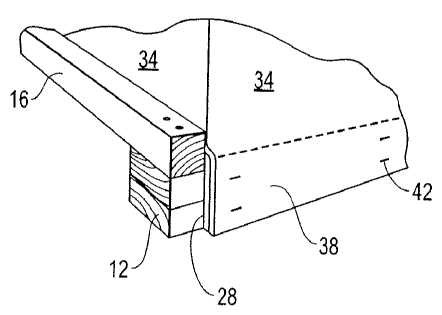
The carton side flaps 38, which have been splayed outward over the
transport base side panels 28 as shown in Figure 10, are then folded
downward so that the transport base side panels 28 are interposed between
the pallet side runners 15 and the carton side flaps 38 as shown in Figure 12.
The carton side flaps 38 and side panels 28 are then removably secured to the
shipping pallet runners 15 by staples 42 or other means.
Figure 13 is a view of the inside of the carton 32 (without the article
50 or corner posts 17), showing how the transport base 18 serves as the
bottom of the package on which the article 50 rests.
CA 02682181 2009-09-18
WO 2008/121538 PCT/US2008/057089
14
Finally, the carton top flaps 40 are folded together to complete the
packaging assembly 10. The finished packaging assembly 10 is unitary in
the sense that the carton 32, transport base 18 and shipping pallet 12 are
secured together by the staples 42 and, to a lesser extent, by the fit of the
carton 32 and transport base 18 between the shipping pallet end stops 16.
The corner posts 17, with or without the caps 19 and top frame 21, extend
from the transport base bottom pane120 to the carton top flaps 40 and
provide sufficient axial (vertical) strength to allow other packaging units 10
to be stacked on top.
Thus there has been described a unitary packaging assembly 10
comprising a shipping pallet 12, a transport base 18 resting on the pallet 12,
a shipping carton 32 enclosing the packaged article 50, and corner posts 17
inserted between the carton 32 and the packaged article 50. In a key aspect
of the invention the transport base 18 and shipping carton 32 are both
secured to the shipping pallet 12 to prevent lateral movement of the
packaged article 50 relative to the shipping pallet 12. The transport base 18
may be made from composite materials, such as paperboard and expanded
polystyrene foam (EPS). The corner posts 17 may be made from paperboard
and the carton 32 may be made from corrugated board. Of course, any
suitable materials may be used for the various packaging assembly
components.
It is understood that the embodiments of the invention described above
CA 02682181 2009-09-18
WO 2008/121538 PCT/US2008/057089
are only particular examples which serve to illustrate the principles of the
invention. Modifications and alternative embodiments of the invention are
contemplated which do not depart from the scope of the invention as defined
by the foregoing teachings and appended claims. It is intended that the
5 claims cover all such modifications and alternative embodiments that fall
within their scope.