Note: Descriptions are shown in the official language in which they were submitted.
CA 02682204 2009-09-28
WO 2008/122110 PCT/CA2008/000615
705075PCT
1
COMPLEX PROJECTOR LENS FOR LED HEADLAMP
FIELD OF THE INVENTION
[0001] The present invention relates to lenses used in conjunction
with LED lights to produce a desired beam pattern.
BACKGROUND OF THE INVENTION
[0002] Typical projector lamps incorporate a reflector and a light
shield. The reflector creates a smooth distribution of light that is imaged by
an
aspheric convex lens onto the road. Projector lamps can also be used along
with light emitting diodes (LED) to provide light that is distributed through
light
guides, typically in the form of fiberoptic cables, and deflected through the
lens. The LEDs can provide a uniform light, points of light, or be surrounded
by dark areas. If a normal lens is used along with the LEDs, the resulting
beam pattern will exhibit any present dark patches. Additionally, performing
additional functions of the projector lamp, such as high-beam and low-beam
functions, also requires controlling the light from a second array of LEDs, so
that they combine with the distribution of the original set of LEDs to produce
a
head lamp beam pattern. Additional LEDs may be illuminated to create a high
beam or fog lamp functions. Other LEDs may be used to produce light
bending functions to aid in seeing around corners. Simply imaging these
arrays would not create a beam pattem that can meet the required optical
performance. Applying a second standard spreader lens to be used with the
LEDs could achieve the required blending; however, it would increase the
number of parts, and decrease the system performance by introducing
additional fresnel losses into the optical system. Adding additional optical
elements between the projector lens and the luminous patches would likewise
add additional parts and decrease system performance.
[0003] Accordingly there exists a need for a lens which can be used
with two or more sets of LEDs to produce various types of beam patterns.
CA 02682204 2009-09-28
WO 2008/122110 PCT/CA2008/000615
705075PCT
2
SUMMARY OF THE INVENTION
[0004] The present invention is a lighting arrangement having at
least one light source, light at least two light pipes for receiving iight
from the
light source, and a lens having two or more sections. The lens is configured
to receive light from at least one of the at least two light pipes, wherein
each
one of the sections projects light in a desired isomeric beam pattern.
[0005] Further areas of applicability of the present invention will
become apparent from the detailed description provided hereinafter. It should
be understood that the detailed description and specific examples, while
indicating the preferred embodiment of the invention, are intended for
purposes of illustration only and are not intended to limit the scope of the
invention.
BRIEF DESCRIPTION OF THE DRAWINGS
[0006] The present invention will become more fully understood
from the detailed description and the accompanying drawings, wherein:
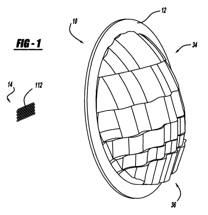
[0007] Figure 1 is a perspective view of a lens and a light pipe
bundle, according to the present invention;
[0008] Figure 2 is a front view of a major group of light pipes, a
minor group of light pipes, and an auxiliary group of light pipes, according
to
the present invention;
[0009] Figure 3 is a front view of a lens divided into horizontal
segments, according to the present invention;
[0010] Figure 4 is a graph depicting a group of isocurves used for
producing a high-beam pattern and a low-beam pattern, produced by a lens,
according to the present invention;
[0011] Figure 5 is a graph of a first group of isocurves, along with a
first source isocurve, produced by a lens, according to the present invention;
[0012] Figure 6 is a graph of a second group of isocurves, along
with a second source isocurve, produced by a lens, according to the present
invention;
CA 02682204 2009-09-28
WO 2008/122110 PCT/CA2008/000615
705075PCT
3
[0013] Figure 7 is a side view of a graph depicting a lens moved
along a vertical plane to create one of the segments shown in Figure 3,
according to the present invention;
[0014] Figure 8 is a lens according to the present invention, taken
along lines 8-8 of Figure 7;
[0015] Figure 9 is a perspective view of a lens and mounting
assembly, according to the present invention;
[0016] Figure 10 is an alternate embodiment of a major group of
light pipes and a minor group of light pipes, according to the present
invention;
[0017] Figure 11 is a front view of an alternate embodiment of a
major group of light pipes, a minor group of light pipes, and an auxiliary
group
of light pipe, according to the present invention; and
[0018] Figure 12 is a perspective view of an alternate embodiment
of a lens, according to the present invention.
DETAILED DESCRIPTION OF THE PREFERRED EMBODIMENTS
[0019] The following description of the preferred embodiment(s) is
merely exemplary in nature and is in no way intended to limit the invention,
its
application, or uses.
[0020] Several components of a lighting arrangement according to
the present invention are shown generally in Figure 1 at 10. The lighting
arrangement 10 includes a lens 12 and a light pipe bundle 14. The light pipe
bundle 14 is used for directing light toward the lens 12 from a light source
(not
shown). Figure 2 shows a front view of the light pipe bundle 14, in this view,
the light is being directed from the light source through the light pipe
bundle
14 out of the page. The light pipe bundle 14 includes at least one light pipe,
and more preferably includes a group of major light pipes 16 receiving light
from a first light source, a group of minor light pipes 18 receiving light
from a
second light source, and a group of auxiliary light pipes 20. The light pipes
16, 18, 20 of the present invention could be fiber optic cabies, or could also
be
CA 02682204 2009-09-28
WO 2008/122110 PCT/CA2008/000615
705075PCT
4
a combination of an LED (Light Emitting Diode) or group of LED's with closely
coupled optics. The light pipes 16, 18, 20 of the present invention could also
be LED's with direct imaging.
[0021] In this embodiment the auxiliary light pipes 20 are divided
into a group of first auxiliary light pipes 22, a group of second auxiliary
light
pipes 24, a group of third auxiliary light pipes 26, a group of fourth
auxiliary
light pipes 28, a group of fifth auxiliary light pipes 30, and a group of
sixth
auxiliary light pipes 32. The major light pipes 16, minor light pipes 18, and
auxiliary light pipes 20 can be used to perform various lighting functions,
such
as producing a high-beam, a low-beam, or a turn signal in an automobile.
More specifically, the major light pipes 16 can be used to produce a wide
beam pattern, and the group of minor light pipes 18 can be used to produce a
"hot spot" beam, where an area of light is intensified. The auxiliary light
pipes
can be used to produce a light bending function, as well as additional hot
15 spot beam patterns.
[0022] Referring back to Figure 1, the lens 12 is divided into various
horizontal sections, shown generally at 34 and vertical sections, shown
generally at 36. The shape of the horizontal sections 34 and the vertical
sections 36 depends on the desired light beam pattern. Referring to Figures
20 4-6, an example of a desired beam pattern is generally shown at 48. The
desired beam pattern 48 is divided into several isocurves. The beam pattern
48 may have as many isocurves as needed to produce the desired beam
pattern 48 with the desired hotspot. In this embodiment, a portion of the
beam pattern 48 is made up a first group of isocurves produced by the major
light pipes 16 shown as the first isocurve 50, second isocurve 52, third
isocurve 54, fourth isocurve 56, and fifth isocurve 58. The remaining portion
of the beam pattern 48 is made up of a second group of isocurves produced
by the minor light pipes 18 shown as sixth isocurve 60, a seventh isocurve 62,
an eighth isocurve 64, and a ninth isocurve 66.
[0023] The isocurves 50, 52, 54, 56, 58, 60, 62, 64, 66 are shown in
Figures 4-6 on a horizontal axis 68 and a vertical axis 70, and represent the
CA 02682204 2009-09-28
WO 2008/122110 PCT/CA2008/000615
705075PCT
area that the desired beam pattern 48 will illuminate. Each isocurve 50, 52,
54, 56, 58, 60, 62, 64, 66 is of a different intensity and illuminates a
different
area of the desired beam pattern 48.
[0024] The first set of isocurves 50, 52, 54, 56, 58 are shown in
5 Figure 5. Also shown in Figure 5 is a typical first source isocurve 72. The
first
source isocurve 72 is the type of isocurve produced when the major light
pipes 16 are used along with a simple aspheric projector lens, for example the
base lens 73 shown in Figure 7, having the appropriate focal length, and not
the modified lens 12 of the present invention. The focal length chosen must
be no shorter than one that will produce an image with a height that is no
more than twice the distance from the center of the smallest zone to be
illuminated and the horizontal axis 68. Images that are larger cannot be
blended to produce the desired vertical image size and will result in patterns
taller than desired.
[0025] The second set of isocurves 60, 62, 64, 66 are shown in
Figure 6, along with a typical second source isocurve 74. The second source
isocurve 74 is the type of isocurve produced when the minor light pipes 18 are
used along with a simple aspheric projector lens, such as the base lens 73
shown in Figure 7, having the appropriate focal length, and not the modified
lens 12 of the present invention. The focal length chosen must be no shorter
than one that will produce an image with a height that is no more than twice
the distance from the center of the smallest zone to be illuminated and the
horizontal axis 68. Images that are larger cannot be blended to produce the
desired vertical image size and will result in patterns taller than desired.
[0026] In order to have the major light pipes 16 produce isocurves
50, 52, 54, 56, 58 when used with the lens 12 of the present invention,
instead
of first source isocurve 72 when the major light pipes 16 are used with the
base lens 73, and for minor light pipes 18 to produce isocurves 60, 62, 64, 66
when used with the lens 12 of the present invention, instead of second source
isocurve 74 when the minor light pipes 18 are used with the base lens 73, the
CA 02682204 2009-09-28
WO 2008/122110 PCT/CA2008/000615
705075PCT
6
following steps for producing the shape of the lens 12 of the present
invention
will now be described.
[0027] The first step in defining the shape of the lens 12 is to
determine the lumen content (amount of luminous flux) of the portion of the
desired beam pattem 48 produced by isocurves 50, 52, 54, 56, 58 by
integrating the intensity of isocurves 50, 52, 54, 56, 58 over the angular
area
covered by the isocurves 50, 52, 54, 56, 58. The lumen output produced by
the major light pipes 16 and controlled by the lens 12 is determined by
integrating the intensity defined in the first source isocurve 72 (produced by
the major light pipes 16 when projected through the aspheric projector lens
described above) over the angular area covered by the first source isocurve
72.
[0028] The lumen content of the portion of the desired beam pattem
48 produced by isocurves 50, 52, 54, 56, 58 and the lumen content produced
by the major light pipes 16 to create the first source isocurve 72 must be
nearly equal. The reason for this is that the lens 12 of the present invention
is
using the light produced by the major light pipes 16, which produce the first
source isocurve 72 when used with the base lens 73, to produce the portion of
the beam pattern 48 made up of isocurves 50, 52, 54, 56, 58 by projecting the
light from the major light pipes 16 through the lens 12 of the present
invention.
If the lumen contents are not equal, then light intensity or area coming from
the major light pipes 16 must be increased, or the desired light intensity
defined by isocurves 60, 62, 64, 66 must be reduced by sacrificing
performance (or the amount of light required) between the isocurves 50, 52,
54, 56, 58 and the isocurves 60, 62, 64, 66 and rebalancing the system by
adjusting the location and/or intensity of the fifth isocurve 58 and sixth
isocurve 60. Once the balance of available vs. desired lumen contact is
achieved for isocurves 50, 52, 54, 56, 58 and isocurves 60, 62, 64, 66 the
detailed shape of the surface of the lens 12 can be defined.
[0029] Referring back to Figure 3, one of the steps for producing the
shape of the lens 12 is achieved by taking the base lens 73, and dividing the
CA 02682204 2009-09-28
WO 2008/122110 PCT/CA2008/000615
705075PCT
7
base lens 73 into horizontal segments 38, 40, 42, 44, 46. The size of each
horizontal segment 38, 40, 42, 44, 46 is selected such that each segment
controls the same amount of lumen content required by an associated
isocurve. The amount of lumen content of each of the isocurves 50, 52, 54,
56, 58, 60, 62, 64, 66 is determined by a process of looking at each of the
isocurves 50, 52, 54, 56, 58, 60, 62, 64, 66 individually taken as a separate
component of the beam pattem 48.
[0030] Beginning with the isocurve having the lowest intensity, the
first isocurve 50, the lumen content is calculated by integrating over the
isocurve's 50 area, assuming the entire area is of uniform intensity. The
average light intensity of the area of the first isocurve 50 is then
subtracted
from the area of all the other isocurves 52, 54, 56, 58, 60, 62, 64, 66. The
lumen content of the isocurve having the next lowest intensity, in this
embodiment the second isocurve 52, is then calculated using the same steps
used to calculate the lumen content of the first isocurve 50. This process
continues until the lumen content of each isocurve 50, 52, 54, 56, 58, 60, 62,
64, 66 is determined. Once the lumen content of each of the isocurves 50,
52, 54, 56, 58, 60, 62, 64, 66 is determined, then size of each of the
segments
38, 40, 42, 44, 46 can then be determined. The process for determining the
size of each of the segments 38, 40, 42, 44, 46 is repeated until the lens
area
required to control the lumen content of each of the isocurves 50, 52, 54, 56,
58, 60, 62, 64, 66 is attained.
[0031] To create each of the segments 38, 40, 42, 44, 46 the
following steps are taken. Referring to Figure 3 and 7, and beginning with
fifth
horizontal segment 46, and the first isocurve 50, the angular distance,
indicated generally at 76, is determined by calculating the anguiar distance
between the center of the first isocurve 50, and the center of the source
isocurve 72 in Figure 5. This forms an angle 78 having a first ray 80 and a
second ray 82 which intersect at a vertex 84. The base lens 73 also includes
an axis 86 and a focal plane 88 which intersect perpendicularly to form a
first
intersection point 90. The base lens 73 also has a rear plane 92 which
CA 02682204 2009-09-28
WO 2008/122110 PCT/CA2008/000615
705075PCT
8
intersects perpendicularly with the axis 86. The angle 78 is positioned such
that the vertex 84 is aligned with the first intersection point 90, and one of
the
rays, in this embodiment the second ray 82, is aligned with the axis 86. When
in this position, the first ray 80 intersects the rear plane 92 to form a
second
intersection point 94, and the second ray 82 intersects the rear plane 92 to
form a third intersection point 96. The base lens 73 is shifted the distance
between the second intersection point 94 and the third intersection point 96,
shown as a vertical distance 97. An upper boundary 98 and lower boundary
100 are chosen and are dependent upon the area to be covered by each
isocurve. The portion of the base lens 73 located between the upper
boundary 98 and lower boundary 100 after the lens 73 is shifted forms the
fifth
horizontal segment 46, which forms a portion of the shape of the lens 12.
[0032] Once the segment 46 is created, the segment 46 is further
divided into multiple horizontal subsegments, generally shown at 102 in
Figure 8. Depending on the size of the subsegments 102, the distance
between the source isocurve 72 and the desired spread of the isocurve 50, a
concave radius of curvature 104 and a convex radius of curvature 106 can be
calculated to allow the light from the isocurve 50 to be deflected over the
desired angle. The concave radius of curvature 104 must be larger than the
convex radius of curvature 106 due to the divergent characteristics of the
light
emitted from the major light pipes 16. The concave radius of curvature 104
and convex radius of curvature 106 are positioned in altemating fashion to
form the lens 12, and the concave radius of curvature 104 connects to the
convex radius of curvature 106 at interconnection points 108 between each of
the concave radius of curvatures 104, the convex radius of curvatures 106,
and the subsegments 102. Note that only a portion of the concave radius of
curvature 104, shown as a concave arc 110, and a portion of the convex
radius of curvature 106, shown as an arc 112 are used to form the lens 12.
[0033] Once the fifth segment 46 is formed, the process described
above is repeated for each isocurve and each segment, until the lens 12
shown in Figure 1 is complete. Once the lens 12 is complete, the lens 12 can
CA 02682204 2009-09-28
WO 2008/122110 PCT/CA2008/000615
705075PCT
9
be installed onto a lamp assembly 114 as shown in Figure 9. The lamp
assembly 114 has a base 116, and a support member 118 for supporting the
lens 12.
[0034] The present invention is not limited to the embodiments
previously described. Instead of having major light pipes 16, minor light
pipes
18, and auxiliary light pipes 20, the present invention can also simply have
major light pipes 16 and minor light pipes 18, and the various light pipes can
be arranged in different ways. The major light pipes 16 can be arranged
above the minor light pipes 18, as shown in Figure 10. Also, the major light
pipes 16, minor light pipes 18, and auxiliary light pipes 20 can be packed
tightly together to form a lighted segment, as shown in Figures 2 and 10, or
each of the major light pipes 16, minor light pipes 18, and auxiliary light
pipes
can be a single large pixel, as shown in Figure 11.
[0035] It should also be noted that the process for defining the
15 shape of the lens 12 of the present invention is not limited to the lenses
described above. The process can also be applied to a lens of Fresnel type
optics as shown in Figure 12 if a reduced maximum thickness is required.
[0036] The description of the invention is merely exemplary in
nature and, thus, variations that do not depart from the gist of the invention
20 are intended to be within the scope of the invention. Such variations are
not
to be regarded as a departure from the spirit and scope of the invention.