Note: Descriptions are shown in the official language in which they were submitted.
CA 02682398 2014-10-07
=
DEVICES, SYSTEMS, AND METHODS FOR CLOSING THE LEFT ATRIAL
APPENDAGE
FIELD
[0002] In general, the devices, systems, and methods described here are for
closing off a portion of tissue, e.g., the left atrial appendage, using a
surgical, minimally
invasive, or intravascular approach.
BACKGROUND
[0003] Atrial fibrillation is a common problem that afflicts millions of
patients.
Unfortunately, atrial fibrillation often results in the formation of a
thrombus, or clot, in the
appendage of the left atrium. This presents a problem, inasmuch as the
thrombus can
dislodge and embolize to distant organs, resulting in adverse events such as a
stroke. For this
reason, most patients with atrial fibrillation are treated with a blood
thinner to help prevent
the formation of a thrombus. Blood thinners, however, can present health risks
(e.g.,
bleeding), particularly in the elderly, and often also require that the user
make significant
lifestyle changes.
[00041 Several methods have been developed to address the potential problem
of thrombus formation in the left atrial appendage. One such method is
suturing along the
base, or ostial neck of the appendage, where it joins the atrial chamber. In
this way, blood
flow into the atrial appendage is cut-off, eliminating the risk of thrombus
formation therein.
This is typically done through open-heart surgery, making the availability of
the procedure
available to only those who are otherwise undergoing an open-heart procedure,
or who are at
particularly high risk. In addition, open-heart surgery requires general
anesthesia and has a
number of well-know risks, making it less desirable.
[0005] Other methods have also been investigated. For example, methods of
stapling the base of the appendage and methods have been investigated, as have
methods of
filling the appendage with a space occupying, or occluding member. However,
stapling is
- I -
PCT/US2008/003938
CA 02682398 2009-09-29
WO 2008/121278 PCT/US2008/003938
not a preferred method given the fragility of the appendage and the likelihood
of its rupture.
Occlusion devices may not effectively prevent all blood flow into the
appendage, leaving
areas of potential thrombus formation.
[0006] Additional devices and methods for closing the left atrial appendage
would therefore be desirable. In particular, devices and methods for closing
the left atrial
appendage using minimally invasive, intravascular, or a combination of these
techniques,
would be desirable in order to avoid the need for opening the chest. Of
course, additional
devices for use in open surgical procedures are desirable as well, especially
when those
devices offer additional advantages over standard devices.
BRIEF SUMMARY
[0007] Described here are devices, systems and methods for closing the left
atrial appendage. Some of the methods described here utilize one or more guide
members
having alignment members to aid in positioning of a closure device. In
general, these
methods comprise advancing a first guide having a first alignment member into
the left atrial
appendage, advancing a second guide, having a second alignment member, into
the
pericardial space, aligning the first and second alignment members, advancing
a left atrial
appendage closure device into the pericardial space and adjacent to the left
atrial appendage,
and closing the left atrial appendage with the closure device. In these
variations, the closure
device typically comprises an elongate body having a proximal end and a distal
end, and a
closure element at least partially housed within the elongate body. The
closure element
comprises a loop defining a continuous aperture therethrough.
[0008] Any of the devices used in any of the methods described here may be
advanced under any of a variety of visualization techniques, e.g.,
fluoroscopic visualization,
ultrasound, etc. For example, the first guide, second guide, or both guides
may be advanced
under fluoroscopic visualization in some variations. Similarly, any of the
devices used in any
of the methods described here may be advanced over a guide element or guide
wire. For
example, the first guide, second guide, closure device, any additional guide,
or any
combination thereof, may be advanced over a guidewire. In some variations, the
second
guide is coupled to the closure device for at least a portion of the method.
[0009] The alignment members may be, or may comprise, any suitable
alignment member. For example, they may be or may comprise magnets, radiopaque
markers, echogenic markings, members configured to produce one or more audible
signals,
- 2 -
PCT/US2008/003938
CA 02682398 2009-09-29
WO 2008/121278 PCT/US2008/003938
interconnecting or interlocking members, one or more vacuum members, or the
like. In some
variations, the alignment members are magnets.
[0010] The first guide may further comprise an expandable member, e.g., an
expandable cage, an expandable strutted structure, an expandable balloon, or
the like. In
some variations, the expandable member comprises an expandable balloon. The
expandable
member may be used for any suitable purpose, e.g., to atraumatically displace
tissue, to help
with identifying, sizing, protecting, isolating, stabilizing, or positioning
tissue, or the like. In
some variations, the expandable member is expanded within the left atrial
appendage. In
other variations of the methods described here, a third guide is advanced into
the left atrial
appendage, where the third guide has a proximal end and a distal end and
comprises an
expandable member. In some additional variations, the first and third guides
are coupled
together for at least a portion of the method. Again, the expandable member
may comprise
any suitable expandable member. In some variations, the expandable member is a
balloon,
which may or may not have one or more apertures therein. The apertures, for
example, may
be useful in enabling inflation and deflation of the balloon, may be useful
for enabling
passage of one or more guides or guidewires therethrough, or may be useful in
enabling
delivery of fluids, such as saline, contrast, drugs, etc., distal of the
balloon.
[0011] The closure device may further comprise a suture for encircling the
left
atrial appendage after it has been closed with the closure device. Of course,
the closure
device may also have the ability to encircle the left atrial appendage without
having a suture
coupled thereto. The closure element alone may capture and release the left
atrial appendage
(i.e., it can open and close around the left atrial appendage), which may help
facilitate
optimal closure of the left atrial appendage, prior to permanent exclusion. In
some
variations, where a suture is used, the suture may comprise a surgical slip
knot. The suture
may or may not be coupled to the closure element.
100121 The methods described here may further comprise tensioning the suture.
The methods may additionally comprise releasing the tension on the suture,
e.g., to help
facilitate repositioning of the device, and the like. The methods may further
comprise
releasing the suture from the closure element, tightening the suture, and
severing the suture.
When the methods include severing the suture, the suture may be severed in any
suitable
fashion. For example, the suture may be severed with a cutting element, or may
be severed
by the application of energy (e.g., light energy, thermal energy, RF energy,
electrical energy,
magnetic energy, electromagnetic energy, kinetic energy, chemical energy and
combinations
- 3 -
PCT/US2008/003938
CA 02682398 2009-09-29
WO 2008/121278 PCT/US2008/003938
thereof). When a cutting element is used, it may be an element on the closure
device itself, or
it may be part of a separate device.
[0013] The methods described here may also include confirming satisfactory or
optimal closure of the left atrial appendage prior to permanent exclusion,
excluding or
opening the left atrial appendage with the closure device, repositioning the
closure device,
reclosing the left atrial appendage, and permanently excluding the left atrial
appendage.
[0014] Other methods for closing the left atrial appendage are also described.
In these methods, a closure device is advanced into the pericardial space and
adjacent to the
left atrial appendage, the left atrial appendage is closed with the closure
device, the left atrial
appendage is secured with a suture, and then the suture is severed. In these
variations, the
closure device typically comprises an elongate body having a proximal end and
a distal end,
and a closure element that comprises a loop defining a continuous aperture
therethrough.
[0015] As with the methods described just above, the severing of the suture
may be accomplished in any suitable fashion. For example, the suture may be
severed with a
cutting element, or by the application of energy (e.g., light energy, thermal
energy, RF
energy, electrical energy, magnetic energy, electromagnetic energy, kinetic
energy, chemical
energy and combinations thereof). When a cutting element is used, it may be an
element on
the closure device itself, or may be part of a separate device, or some
combination of both
may be used.
[0016] The closure device may comprise one or more expandable elements, and
the closure device, the suture, or both may comprise a radiopaque material,
echogenic
material, or some combination thereof In some variations, the closure device
is made from a
shape-memory material (e.g., a nickel titanium alloy, or the like), and in
some variations, the
suture is coupled to the closure device. In these methods, the closure device
may be
visualized while advanced, e.g., using fluoroscopy, ultrasound, a combination
thereof, etc.,
and may or may not be advanced over a guide element or guidewire.
[0017] Additional methods for closing a left atrial appendage are also
described
here. These methods typically comprise advancing a first guide having a
proximal end and a
distal end into the left atrial appendage, through the left atrial appendage,
and out of the left
atrial appendage, such that one of the proximal or distal ends is within the
vasculature, and
one of the proximal or distal ends is within a subthoracic space, and
advancing a left atrial
appendage closure device into the pericardial space and adjacent to the left
atrial appendage,
- 4 -
PCT/US2008/003938
CA 02682398 2009-09-29
WO 2008/121278 PCT/US2008/003938
and closing the left atrial appendage with the closure device. In these
methods, the closure
device typically comprises an elongate body having a proximal end and a distal
end, and a
closure element housed within the elongate body, where the closure element
comprises a loop
defining a continuous aperture therethrough.
[0018] In these methods, the proximal end of the first guide may be within the
vasculature, or within the stubthoracic space. In some variations, the closure
device is
advanced into the pericardial space over the first guide. Again, as with all
the methods
described here, any of the devices may be advanced under any of a variety of
visualization
techniques. For example, the first guide, closure device, or both may be
advanced under
fluoroscopic or ultrasound visualization, or both. In some variations, the
methods further
comprise advancing a second guide into the left atrial appendage, where the
second guide has
a proximal end, a distal end, and comprises an expandable member. The
expandable member
may be any suitable expandable member (e.g., expandable struts, expandable
cage,
expandable balloon, or the like). In some variations, the first and second
guides are coupled
together for at least a portion of the method.
[0019] Devices for closing the left atrial appendage are also described here.
Some of the devices described here comprise an elongate body having a proximal
end and a
distal end, a closure element comprising a loop defining a continuous aperture
therethrough at
least partially housed within the elongate body, and a suture loop. The suture
loop may or
may not be coupled to the closure element. For example, the device may further
comprise a
retention member, where the retention member is configured to retain the
closure element and
the suture loop. The retention member may be configured to accomplish this
task in any
suitable fashion. For example, it may comprise first and second lumens, where
the closure
element is housed within the first lumen and the suture loop is housed within
the second
lumen. The second lumen may have a weakened region, a perforated region, or a
slit or other
opening configured to release and/or close the suture with the application of
a force. In other
variations, the retention member and the closure element are withdrawn or
otherwise
removed, leaving behind and/or closing the suture loop. In still other
variations, the retention
member comprises a first lumen and one or more releasable retention elements,
where the
closure element is housed within the first lumen and the suture loop is
retained by the one or
more releasable retention elements. The retention element may be any suitable
element, for
example, a releasable prong, a polymer tack, and the like.
- 5 -
PCT/US2008/003938
CA 02682398 2009-09-29
WO 2008/121278 PCT/US2008/003938
[0020] The closure element may be made from any suitable material. In some
variations, the closure element is made from a shape-memory material (e.g., a
nickel titanium
alloy). Similarly, the suture loop may be made from any suitable material
(e.g., any suitable
material useful for exclusion or closure). It may be bioabsorbable (e.g.,
biodegradable
polymers, etc.), or non-bioabsorbable (e.g., non-biodegradable polymers,
metals, etc.). The
closure element, suture loop, or both may comprise a radiopaque or echogenic
material.
[0021] In some variations, the elongate body has one or more curves along its
length. The elongate body may or may not be steerable, and may or may not be
configured as
a catheter. In some variations, the closure element and the suture loop are
separately
actuatable. In other variations, the device further comprises a cutting
element.
[0022] Systems for closing a left atrial appendage are also described here.
Typically, the systems comprise a first guide having a size and length adapted
for accessing
the left atrial appendage through the vasculature, where the first guide
comprises a first
alignment member, a second guide having a size and length adapted for
accessing the
pericardial space from a subthoracic region, where the second guide comprises
a second
alignment member, and a closure device comprising an elongate body having a
proximal end
and a distal end, and a closure element housed at least partially therein,
where the closure
element comprises a loop defining a continuous aperture therethrough. The
system may
further comprise any suitable or useful device or component.
[0023] For example, in some variations the system further comprises an
expandable member. The expandable member may be any suitable expandable
member, and
in some variations the expandable member is an expandable balloon with or
without one or
more apertures therein. The expandable member may be configured to be
couplable to the
first guide.
[0024] The systems described here may further comprise a suture, which may
or may not be coupled to, or couplable with, the closure device. The systems
may also
comprise a device or element for severing the suture. In some variations, the
closure device
is couplable to the second guide.
[0025] The first and second alignment members may be any suitable alignment
members. For example, they may be or may comprise magnets, radiopaque markers,
echogenic markings, members configured to produce one or more audible signals,
interconnecting or interlocking members, one or more vacuum members, or the
like. In some
- 6 -
PCT/US2008/003938
CA 02682398 2009-09-29
WO 2008/121278 PCT/US2008/003938
variations, the alignment members are magnets, which may or may not be located
at the distal
ends of the first and second guides. The systems may further comprise
instructions for using
the first guide, second guide, closure device, or any combination thereof. In
some variations,
the elongate body of the closure device has one or more curves along its
length, and the
systems further comprise a straightening tube, configured to temporarily
straighten the one or
more curves.
BRIEF DESCRIPTION OF THE DRAWINGS
[0026] FIG. 1 provides a cross-sectional representation of a heart showing
various anatomical structures.
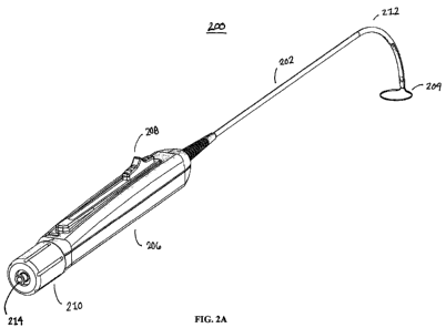
[0027] FIGS. 2A-2B are different views of an illustrative device that may be
used with the systems and methods described herein.
[0028] FIG. 3A provides a close-up view of a distal end of an illustrative
device
having a retention member.
[0029] FIGS. 3B-3D depict illustrative retention members that may be used
with the devices described herein.
[0030] FIG. 4 provides a close-up view of a distal end of an illustrative
device,
without a retention member.
[0031] FIG. 5 is a depiction of an illustrative device with the catheter body
removed for purposes of description and clarity.
[0032] FIG. 6 provides another depiction of an illustrative device with the
catheter body removed, here, showing more of the device.
[0033] FIG. 7 is a close-up view of an illustrative suture retention
mechanism,
here, shown as a suture hook.
[0034] FIG. 8 is a close-up view of a distal end of an illustrative device
having
a lumen therethrough.
[0035] FIG. 9 is a top side view of one variation of the proximal end of the
devices described here.
- 7 -
PCT/US2008/003938
CA 02682398 2009-09-29
WO 2008/121278 PCT/US2008/003938
[0036] FIG. 10 is a skewed end view of one variation of the proximal end of
the
devices described here.
[0037] FIG. 11 provides a cross-sectional view of one variation of the
proximal
end of the devices described here.
[0038] FIG. 12 is an illustrative suture cutter that may be used with the
systems
and methods described here.
[0039] FIGS. 13A and 13B are illustrative guides having alignment members.
[0040] FIGS. 14A-14D depict an illustrative method of closing the left atrial
appendage.
[0041] FIGS. 15A-15D depict an alternative illustrative method of closing the
left atrial appendage.
[0042] FIG. 15E depicts an illustrative device that may be used to perform the
method depicted in FIGS. 15A-15D.
DETAILED DESCRIPTION
[0043] Described here are devices, systems, and methods for closing the left
atrial appendage. In this regard, it may be helpful to start by briefly
identifying and
describing the relevant heart anatomy. Shown in FIG. 1 is a cross-sectional
view of the heart
(100). Shown there is left atrium (102) and left ventricle (104). In between
the left atrium
(102) and the left ventricle (104) is the mitral valve (also known as the
bicuspid valve), which
is defined by a pair of mitral valve leaflets (106). The leaflets are
connected to chordae
tendinae (108) that are in turn, connected to papillary muscles (110). The
papillary muscles
join ventricular wall (112). The left atrial appendage (114) is shown adjacent
to, and is
formed from, the wall of the left atrium (102).
[0044] As can be seen, the left atrial appendage (114) lies within the
boundaries
of the pericardium (116), and is in close proximity to the ventricular wall
(112). The left
atrial appendage typically has a tubular shape that approximates a cone, with
a slight
narrowing or neck in the plane of the orifice where it joins the left atrium
(102). In patients
with atrial fibrillation, the left atrial appendage (114) is the most common
location for
thrombosis formation, which, in time, may dislodge and cause a devastating
stroke. Because
- 8 -
PCT/US2008/003938
CA 02682398 2009-09-29
WO 2008/121278 PCT/US2008/003938
stroke is the primary complication of atrial fibrillation, the left atrial
appendage is frequently
excluded from the left atrium in those patients undergoing procedures to treat
atrial
fibrillation, and is often removed or excluded at the time of other surgical
procedures, such as
mitral valve surgery, to reduce the risk of a future stroke. The devices and
systems described
here, help ensure proper closure of the left atrial appendage, at the neck or
base of the left
atrial appendage, along the anatomic ostial plane. In this way, exclusion of
the entire left
atrial appendage from systemic circulation may be facilitated.
I. Devices
[0045] The devices described here for closing the left atrial appendage
generally comprise a closure element having one or more loops. The devices may
be suitable
for use with minimally invasive access to the left atrial appendage (e.g.,
through a small sub-
xyphoid or other intercostal incision, through an incision in the costal
cartilage, through a
port, through the vasculature, etc.) or may be suitable for use with open
surgical procedures.
The lengths of the devices may be chosen as desirable.
[0046] FIGS. 2A and 2B provide different views of an exemplary device that
may be used to close the left atrial appendage. Shown in FIG. 2A is device
(200) comprising
an elongate body (202) having a proximal end and a distal end, and a closure
element (204).
In this variation, the closure element comprises a loop that defines a
continuous aperture
therethrough suitable for encircle the left atrial appendage therein. The
closure element is at
least partially housed within the elongate body (202) and may be advanced
therefrom, or
retracted therein. Also shown in FIG. 2A is a lumen (214) for passage of a
tools or fluids
therethrough. For example, the lumen (214) may enable passage of a guide (with
or without
an alignment member), a guidewire, a suture cutter, fluids and/or drugs, and
the like. Any
number of lumens may be used for any suitable purpose. Suitable lumens will be
described
again with reference to FIG. 8. Also shown in FIGS. 2A and 2B is handle (206)
having a
linear actuation slide (208) and knob (210). Additional details of the handle
will be discussed
below.
[0047] In the variation shown in FIGS. 2A and 2B, the elongate body (202)
comprises a curve (212) at a distal portion thereof. In instances where the
elongate body
(202) of the device comprises one or more curves, a straightening tube, or
other straightening
mandrel or mechanism may be used to temporarily straighten the elongate body
during
delivery (e.g., until the pericardial space is reached). After a particular
location has been
- 9 -
PCT/US2008/003938
CA 02682398 2009-09-29
WO 2008/121278 PCT/US2008/003938
reached, the straightening tube or mandrel may then be withdrawn. The
straightening tube
may be made of any suitable material (e.g., a rigid plastic, stainless,
combination thereof,
etc.). Of course, it should be understood that the device need not comprise
one or more
curves as shown in FIGS. 2A and 2B. For example, the elongate body may be
straight and
flexible, and a pre-curved tube or mandrel may be employed during the methods
to aid in
delivery and use (e.g., while advanced to the left atrial appendage).
Similarly, the elongate
body may be straight and flexible, and have a pull wire attached thereto, so
that when the
pullwire is pulled proximally, the elongate body flexes and bends. In this
variation, the
elongate body may be maneuvered as appropriate. It should be understood that
any of the
devices described here may be configured for steerability, or may be
configured for robotic
use (e.g., configured for use with one or more robotic or other automated type
device).
[0048] FIG. 3A provides additional detail of a suitable closure element. Shown
there is a distal portion (300) of a suitable closure device having an
elongate body (302) and a
closure element assembly (304). In FIG. 3A, details of an elongate body
extension, or tip
(306) can be seen. This tip may be thermoformed or injection molded, or may be
integral
with the rest of the elongate body (302). In instances where a suture loop
(308) is used, the
tip (306) may serve to house a suture knot therein. It should be understood
that when
reference is made to the elongate body, it is meant to include any such tip
(306) as shown in
FIG. 3A. Also apparent in FIG. 3A is suture loop (308), which is shown passing
through the
tip (306) in a proximal direction and into a retention member (312) in a
distal direction. Also
shown passing through tip (306) in a proximal direction and into retention
member (312) in a
distal direction is closure element (310), which will form a loop to encircle
the left atrial
appendage. As can be seen by FIG. 3A, the retention member is configured to
retain the
closure element and the suture loop.
[0049] FIGS. 3B-3D depict illustrative retention members that may be used
with the devices described herein. FIG. 3B shows an end view of a retention
member (314)
having first and second lumens (316, 318) for retaining a closure element and
a suture loop
therein. In this variation, the second lumen (318) has a slit or other opening
(320) along its
length, for allowing the suture to pass therethrough when it is ready to be
deployed. Of
course, it should be understood that the first and second lumens may be
positioned or oriented
in any suitable way with respect to each other, and similarly, the slit or
other opening on the
second lumen may be positioned or oriented in any suitable fashion with
respect to the first
lumen (e.g., it may be approximately 180 , approximately 150 , approximately
120 ,
- 10-
PCT/US2008/003938
CA 02682398 2009-09-29
WO 2008/121278 PCT/US2008/003938
approximately 90 , approximately 60 , approximately 300, or the like, from the
first lumen
(316)). FIG. 3C provides an illustration of a retention member having a first
lumen (322), a
second lumen (324), and a slit (326). In this variation, the slit (326) is
positioned closer to
the first lumen (322) than the slit of FIG. 3B. The width or spacing of the
slit opening may
selected as desired or appropriate. Similarly, the slit need not extend or be
continuous along
the entire length of the retention member. In some variations, the slits may
have prongs or
arms along its length to help capture and retain the suture therein. In other
variations, the
slits may be covered at spaced apart locations therealong with a biodegradable
polymer,
temporarily used to tack or hold down the suture. Of course, in still other
variations, the
retention member does not comprise a slit, and instead comprises some other
type of
retention mechanism, such as the prongs or tacks described just above. In yet
other
variations, there are no slits or openings in the retention member and the
suture loop is
released upon removing or withdrawing the retention member and closing the
device.
[0050] FIG. 3D provides another variation of a retention member. In this
variation, the retention member has a first lumen (328), second lumen (330),
and a separation
region (332). The separation region may be constructed in any suitable
fashion. For
example, the separation region may comprise a perforated region adapted to
perforate and
release the suture with the application of force. Alternatively, the
separation region may be a
thin-walled or other type of weakened region that may be configured to break
and release the
suture. It should be understood that the retention member may have any
suitable geometry or
shape, and may be made from any suitable material. Similarly, the lumens need
not be full
circles or have a circular cross-sectional geometry. When these or other types
of retention
members are used, the suture loop may be torn out, pulled through, or
otherwise released
from the retention member after it has been properly positioned and tightened
as desirable.
[0051] The above described components may be made of any suitable material.
For example, the closure element may be made from a shape-memory material,
such as a
shape-memory alloy (e.g., nickel titanium alloy, etc.), may be made from
stainless steel,
polyester, nylon, polyethylene, polypropylene, some combination thereof, etc.
Similarly, the
suture loop may be made of any suitable material useful in exclusion or
closure, and the term
"suture loop" should be understood accordingly. For example, it may be made of
a
biodegradable material (e.g., polylactic acid, polyglycolic acid, polylactic-
co-glycolic acid,
etc.), or may be made of a non-biodegradable material (e.g., metal, steel,
polyester, nylon,
propylene, silk, and combinations thereof). In some variations, as will be
described in more
- 11 -
PCT/US2008/003938
CA 02682398 2009-09-29
WO 2008/121278 PCT/US2008/003938
detail below with reference to the methods, the suture loop is made from a
biodegradable
material such that the suture loop degrades after a period of time has elapsed
(e.g., for
sufficient scarring to be achieved). It should be understood, the any part of
the device may
comprise, include, or be made from a radiopaque or echogenic material to help
facilitate
visualization. For example, the closure element, the suture loop, the elongate
body, or any
combination of these components may comprise a radiopaque or echogenic
material.
[0052] The suture loop and the closure element may be configured to have any
appropriate perimeter. For example, they may have a perimeter of 4.5 inches in
a fully
expanded state, a perimeter of about 4.3 inches, about, 3.3 inches, about 4.0
inches, about 3.5
inches, about 3.3 inches, 3.0 inches, about 2.7 inches, about 2.5 inches,
about 1.5 inches,
about 1.25 inches, or the like. Of course, these perimeters will vary as the
closure element
and suture loop are actuated and retracted.
[0053] For additional clarity, FIG. 4 provides a view of distal portion (300)
of
FIG. 3A, without retention member (312), thus showing the looped nature of
closure element
(310) and suture (308). FIG. 5 is a view of distal portion (300), without
retention member
(312), tip (306), and elongate body (302), thus providing additional details
of this variation of
the device. Shown there is of course, closure element (310) and suture (308).
Suture (308)
further comprises a surgical knot (e.g., a one way slipknot or other suitable
knot) (500). Also
shown is an anchoring feature (502), here shown as a tube, for anchoring one
side of the
closure element (310). The opposite side of the closure element is the active
or actuation side
(i.e., one side remains anchored while the other side has additional active
length). Of course,
when anchoring is used, it may be done in any suitable way. In other
variations (not shown
here), both sides of the closure element are active and actuatable (i.e.,
neither side is
anchored). The device may also comprise a suture tube (504) for facilitating
suture passage.
[0054] FIG. 6 shows additional proximal detail of a suitable closure device.
In
this view, the elongate body and tip have been removed, but the retention
member remains.
Of particular interest here is suture hook (600). Suture hook (600) captures
suture loop (308)
so that the closure element (310) may be advanced and retracted separately
from suture loop
(308) when the two are coupled together. That is, the suture hook (600)
prevents the suture
from tightening as the closure element is actuated, so that the device may be
positioned as
desirable before the suture is actuated. The suture hook (600) may also help
prevent excess
suture from opening and closing, and thus help prevent excess suture from
getting caught on
anatomical structures, instruments, etc. Also shown in FIG. 6 is a proximal
length of the
- 12 -
PCT/US2008/003938
CA 02682398 2009-09-29
WO 2008/121278 PCT/US2008/003938
closure element (602). In some variations, it may be useful to have at least a
portion of the
proximal length of the closure element (602) coated with a lubricious coating,
in order to help
facilitate slidable actuation. Any suitable lubricious coating may be used
(e.g., PTFE, etc.).
The suture hook (600) is shown in greater detail in FIG. 7. While the suture
hook shown in
FIG. 7 has a rounded atraumatic tip, it need not be so. Indeed, any suitable
tip may be used.
The suture hook may be made of any suitable material.
[0055] FIG. 8 provides details of the distal portion of an illustrative
closure
device (800), here comprising at least one lumen (802) in the elongate body
(804). The
lumen may be used for any suitable purpose. For example, it may be used to
enable passage
of one or more guides or guidewires therethrough, one or more tools
therethorugh, or the like.
The lumen may also be used as a flush lumen, a vacuum lumen, a drug delivery
lumen, or the
like. The elongate body may comprise any number of lumens, and it should be
understood
that the lumens need not traverse the entire length of the elongate body, nor
form a
completely bounded aperture (i.e., the use of lumens herein is intended to
capture instances
where a slit or groove may be used with one or more guides, guidewires, or
additional tools).
[0056] FIG. 9 is one variation of a suitable handle (900) for the devices
described herein. In this variation, the handle comprises a linear actuation
slide (902) for
actuating the closure element, and a suture knob (904) for actuating the
suture. While not
shown, the suture hook, described above, or similar such feature, helps enable
the separate
actuation capability described here. Thus when the slide (902) is pushed
distally, the closure
element, which has been at least partially retained within the elongate body,
will be advanced
distally, and the loop size of the closure element will get bigger.
Conversely, when the slide
is retracted proximally, the closure element will be retracted and the loop
size will get
smaller. The suture loop is not affected in this process. Instead, the suture
loop in this
variation is controlled by the suture knob. Of course, the suture loop need
not be actuated by
a knob. That is, the suture may be separately actuated by an additional slide,
lever, button, or
the like. Similarly, the closure element need not be actuated by a slide. It
may be actuated by
a button, knob, lever, or the like.
[0057] Also shown in FIG. 9 is suture cutting slot (906). While not easily
shown in this view, the suture runs through the handle and into the knob. The
suture cutting
slot enables the suture to be cut easily, as the suture traverse the slot and
the slot provides a
viewing window and access point for suture severing. Of course, the suture
need not be
severed in such a fashion. In some variations, the closure device itself
comprises a cutting
- 13 -
PCT/US2008/003938
CA 02682398 2009-09-29
WO 2008/121278 PCT/US2008/003938
element for severing the suture (e.g., a blade actuated by a button or some
other mechanism).
FIG. 10 provides a skewed end view of the handle shown in FIG. 9 so that
additional details
may be seen. Specifically, shown here are suture knob lock (1000) and luer
fitting (1002) at
the proximal end of the handle lumen.
[0058] FIG. 11 provides a cross-sectional view of a portion of handle (1100),
here showing a length of the handle including the suture knob (1102) and the
slide actuator
(1104) in its most retracted position. Suture knob (1102) comprises an outer
knob (1106),
and outer knob bearing (1108), inner knob (1110) and inner knob bearing
(1112), thrust
bearing (1114) and slip clutch plates (1116) that when actuated (when the knob
(1102) is
turned or rotated) apply a tension upon the suture loop causing it to release
from the retention
member. In one variation, the slip clutch plates (1116) have particular force
settings and are
configured to provide tactile feedback to the operator indicating closure. In
other variations,
the clutch plates (1116) may have a particular force limitation in order to
protect against
shearing or cutting of tissue by the suture during release or tightening of
the suture loop. For
example, in these variations, once the suture loop reaches a pre-determined
force, the outer
knob (1106) and outer knob bearing (1108) may disengage from inner knob (1110)
and inner
knob bearing (1112) by slipping or the like (e.g., similar to a gas cap when
overtightened).
[0059] Also shown is a suture reel area (1118) and a suture severing slot
(1120), which, as described briefly above, is used to help terminate the
suture by placement
of blade, scalpel, or other sharp instrument therein. As described above, in
some variations,
the closure device itself comprises a suture cutting device or mechanism, and
this may be
located at the same place as the suture severing slot (1120) or some other
place. For
example, the device may include a blade or other cutting mechanism that may be
actuated by
a blade, lever, knob, etc., whether or not located in the suture severing slot
location. Lumen
(1122) may be used for placement of a guide (with or without an alignment
member),
guidewire, one or more tools (e.g., a suture cutter, visualization devices,
etc.), one or more
fluids (e.g., saline, drugs, etc.), as described above.
II. Methods
[0060] Methods for closing the left atrial appendage are also described here.
The left atrial appendage may be accessed in any suitable fashion, and any of
the devices
described here may be used. For example, the left atrial appendage may be
accessed from the
inside of the heart, or may be accessed from the outside of the heart. In some
variations, the
- 14 -
PCT/US2008/003938
CA 02682398 2009-09-29
WO 2008/121278 PCT/US2008/003938
left atrial appendage is accessed from both the inside of the heart, and the
outside of the heart.
Typically, the appendage is closed off from the outside of the heart, even
when accessed from
the inside of the heart.
[0061] In variations when the left atrial appendage is accessed from both the
inside and the outside of the heart, it may be useful to employ the use of
guides having
alignment members. In this way, accessing the left atrial appendage may be
more easily
facilitated. It may also be useful to employ the use of a positioner or
stabilizer, to help
position devices relative to the left atrial appendage and to stabilize the
appendage while it is
being closed off. The positioner or stabilizer may be any suitable stabilizer
or positioner,
e.g., an expandable member or the like. More details of this will be described
below.
[0062] In some variations, the methods of closing the left atrial appendage
comprise advancing a closure device into the pericardial space and adjacent to
the left atrial
appendage, closing the left atrial appendage with the closure device, securing
the closed left
atrial appendage with a suture, and then severing the suture. The closure
device may be any
suitable closure device, such as a device having an elongate body with a
closure element
comprising a loop defining a continuous aperture therethrough, as described
above. The
suture may be severed in any suitable fashion, and at any suitable location
along its length
(i.e., from immediately adjacent to the knot at the left atrial appendage to
just proximal to, or
just distal to, the skin surface). In some instances it may be desirable to
sever the suture at
the knot itself (e.g., in instances where it is desirable to release tension
on the suture entirely).
[0063] An illustrative device (1200) for severing a suture is shown in FIG.
12.
The device depicted there may be threaded over the suture and then actuated to
cut the suture
with a blade or similar cutting feature housed within distal portion (1202).
While a device
having a blade housed therein is depicted in FIG. 12, any suitable cutting
device may be used,
and the device may be made from or comprise any suitable materials (e.g., a
radiopaque or
echogenic material). In some variations, the closure device has a cutting
element thereon, for
cutting the suture. Of course, the suture need not be severed with a blade or
other such
cutting feature. The suture can be severed by the application of energy. For
example, the
suture may be severed with the application of light energy, thermal energy, RF
energy,
electrical energy, magnetic energy, electromagnetic energy, kinetic energy,
chemical energy,
and combinations of any of the above. Additional methods will now be
described.
- 15-
PCT/US2008/003938
CA 02682398 2009-09-29
WO 2008/121278 PCT/US2008/003938
A. Transseptal and Pericardial Access
[0064] In some variations, the methods for closing the left atrial appendage
include accessing the left atrial appendage from both the inside of the heart
and the outside of
the heart. In these variations, one or more guides having alignment members
are often used
to align the inside and outside access devices together. To access the inside
of the heart, the
vasculature is typically used. For example, access may be obtained via one or
several of the
various veins or arteries (jugular, femoral, carotid, etc.). In some
variations, the heart is
accessed on the inside via the common femoral vein (e.g., the left common
femoral vein)
using a standard Seldinger technique with a needle. An introducer wire may
then be
advanced through the needle, followed by an introducer sheath. The introducer
wire may
then be removed. In some variations, a guiding catheter sheath may be placed
as an
alternative to an introducer sheath or the initial sheath may be replaced with
a guiding
catheter sheath.
[0065] Using fluoroscopy, an angiogram performed through the sheath, a
catheter placed through the sheath, a guiding catheter sheath, or any
combination thereof,
may be performed to observe anatomical characteristics and considerations of
the access
route for the purpose of transseptal access into the left atrium (e.g.,
tortuosity, clots, devices,
such as vena cava filters, etc.). Fluoroscopy, ultrasound, intracardiac
echocardiography,
extracardiac echocardiography, transesophageal echocardiography, or
combinations thereof,
may be used to help visualize transseptal access to the left atrium, and
access to the left
atrium may be obtained using standard transseptal access techniques.
[0067] For access to the heart from the outside, a subthoracic access point
may
be used. The access point is typically identified based on patient anatomic
characteristics. In
some variations, the access point is right of the xyphoid process and pointed
towards the
patient's left shoulder, but may be at any suitable location (e.g.,
intercostal access via a
sternotomy, thoracostomy, or thoracotomy, or in the costal cartilage itself).
Once the access
point has been determined, a needle (e.g., a 17G Tuohy needle) may be advanced
using
standard pericardiocentsesis techniques under fluoroscopic guidance. After
access to the
pericardium has been obtained, a guidewire may be advanced through the needle
under
fluoroscopic visualization within the pericardiac sac. The needle may then be
removed.
Access to the pericardial space has thus been obtained.
- 16-
PCT/US2008/003938
CA 02682398 2009-09-29
WO 2008/121278 PCT/US2008/003938
[0068] Turning now to the figures, after access from the inside and outside of
the heart has been obtained using the above described devices and techniques,
the devices of
the current invention are ready for use. For example, first (1300) and second
(1302) guides
having alignment members as shown in FIGS. 13A and 13B respectively may be
used to
guide the procedure. The alignment member may be any suitable alignment member
(e.g.,
interconnecting elements, one or more vacuum members, radiopaque or echogenic
markers,
members that are configured to produce an audible response, magnets, etc.).
Here, the
alignment members are magnets (1304, 1306) located at the distal ends of the
guides. The
magnets may be made from or comprise any suitable magnetic material, e.g., a
rare earth
magnet, such as neodymium-iron-boron, cobalt-samarium, or other powerful fixed
magnet
elements. These guides may be used for guiding additional tools and/or devices
to the left
atrial appendage.
[0069] The guides may have any suitable lengths and/or dimensions. For
example, the guides may have a diameter of about 0.010" to about 0.050", about
0.020" to
about 0.030", or the like. In some variations the first guide has a diameter
of about 0.025"
and the second guide has a diameter of about 0.035". Similarly, the length may
be any
suitable length. For example, from about 50 cm to about 300 cm or more, from
about 100 cm
to about 200 cm, from about 200 cm to about 250 cm, and the like. In some
variations, the
first guide has a length of about 250 cm and the second guide has a length of
about 90 cm.
The outer diameter of the alignment element may also be selected as desirable.
For example,
it may be from about 0.05" to about 0.2" or more. In some variations, the
outer diameter of
the alignment member of the first guide is about 0.106" and the outer diameter
of the
alignment member of the second guide is about 0.170". It should be understood
that these
dimensions are suitable for any guide, not only guides having alignment
members comprising
one or more magnets.
[0070] For example, turning to FIG. 14A, the first guide (1400) may be
advanced into the left atrial appendage (1404), while the second guide (1402)
may be
advanced into the pericardial space adjacent to the left atrial appendage.
Either of these
guides may be advanced under any of a variety of visualization techniques,
e.g., fluoroscopic
visualization, ultrasound visualization, some combination thereof, etc. A
balloon catheter
(1406) or other expandable member may be advanced over the first guide, or in
conjunction
with the first guide (e.g., it may be coupled to or be part of the first
guide) and into the left
atrial appendage as shown in FIG. 14B. Similarly, a closure device (1408) may
be advanced
- 17-
PCT/US2008/003938
CA 02682398 2009-09-29
WO 2008/121278 PCT/US2008/003938
over the second guide, or in conjunction with the second guide (e.g., it may
be coupled to or
be part of the second guide), as shown in FIG. 14B.
[0071] In instances where a balloon is used as an expandable member, it may be
made of any suitable material. For example, it may be made of polyisoprene, or
other
suitable materials. Similarly, the balloon may have any suitable dimensions.
For example, it
may have an outer diameter of approximately 10-40 mm, approximately 20-30 mm,
or the
like. Similarly, it may have any suitable length. For example, it may have a
length of about
mm to about 50 mm, about 10 mm to about 20 mm, or the like. In some
variations, the
balloon has an outer diameter of approximately 20-30 mm, and a length of about
20 mm.
[0072] The expandable member (in this variation, shown as an expandable
balloon) is inflated to position and stabilize the left atrial appendage, as
shown in FIG. 14C.
In its expanded state, the expandable member helps locate the ostial plane of
the left atrial
appendage. Specifically, when the expandable member is expanded, the left
atrial appendage
is distended and its shape is changed from roughly conical to roughly
spherical, thus better
defining the junction between the left atrial appendage and left atrium. In
addition, the
expandable member in its expanded state may be at a pressure much greater than
that of the
left atrium proper, resulting in a significant differential in tension between
the left atrial
appendage and the left atrium. The expandable member may have one or more
apertures
therethrough for passage of contrast to facilitate visualization.
[0073] While the expandable member is still in its expanded state, a closure
element (1410) of a closure device (1408) may be placed around the left atrial
appendage and
closed as shown in FIG. 14D. However, in some variations, the closure element
is placed
around the left atrial appendage while the balloon is in its deflated or
unexpanded stated, and
then the balloon is expanded. A suture may then be deployed from the device,
tightened
around the closed appendage, released from the device, and severed, leaving
the closed
appendage in place. Of course, in some instances it may be desirable to
confirm proper
closure of the appendage prior to tightening of the suture, and then again
after the suture has
been tightened using fluoroscopic or other visualization techniques. If
closure is not adequate
or otherwise not desirable, the loop may be opened, repositioned, closed, and
then confirmed
once again.
[0074] Specifically, it is desirable that the left atrial appendage be closed
off as
close to the anatomical ostial plane as possible (i.e., the opening that
separates the left atrium
- 18-
PCT/US2008/003938
CA 02682398 2009-09-29
WO 2008/121278 PCT/US2008/003938
from the left atrial appendage). If the left atrial appendage is closed off
above the plane of
the orifice (toward the left atrial appendage tip or away from the anatomical
ostial plane), this
may result in a persistent diverticulum of the left atrial appendage, which in
turn may result
in an additional site or nidus for thrombus formation despite complete
exclusion of the left
atrial appendage from the left atrium. In some individuals, the geometry of
the left atrium
and left atrial appendage may be such that the neck or narrowing between them
is poorly
defined from the epicardial, or outer aspect. In addition, the external
geometry of the left
atrial appendage-left atrial junction is difficult to differentiate from an
epicardial perspective.
This may be compounded by the fact that the anatomy is moving vigorously when
the
procedures are employed while the heart is beating and the lungs remain
inflated (i.e., closed
chest procedures). From an inside aspect, or endocardial view, fluoroscopy and
ultrasound
methods provide limited information or ability to landmark the true three-
dimensional
characteristics of the anatomic ostial plane. Thus the use of the devices
described here help
facilitate proper positioning and closure of the left atrium, and may be used
during beating
heart procedures, thus resulting in significant advantages over known left
atrial appendage
closure devices.
[0075] Of course, many variations on this method are possible. For example,
the guides may be used as guidewires or rails for additional devices to slide
over, or the
guides may be coupled to the devices described just above. Additional guides
or guidewires
may also be used, and confirmation steps may be used throughout as
appropriate. The guides
having the alignment members thereon may be used or removed during the methods
as
appropriate or desirable. In some variations, the closure device has one or
more bends or
curves along its length, and a tip straightener or straightening tube is used
to temporarily
straighten the bend during advancement of the device into the pericardial
space. In other
variations, where the device includes a straight elongate body, a pre-curved
device may be
used to aid in delivery after proper access has been obtained. In some
variations, the suture
loop is made from a biodegradable material and is configured to biodegrade
after sufficient
time has passed to ensure scarring or formation of new tissue that effectively
seals of the
appendage.
B. Transseptal or Pericardial Access
[0076] In the methods described just above, access to the left atrial
appendage
was obtained both from inside and outside the heart. Of course, the left
atrial appendage may
be closed off using the systems and devices described here without performing
both access
- 19-
PCT/US2008/003938
CA 02682398 2009-09-29
WO 2008/121278 PCT/US2008/003938
procedures as described above. For example, in some variations the methods
comprise
advancing a first guide having a proximal end and a distal end into the left
atrial appendage,
through the left atrial appendage, and out of the left atrial appendage, such
that one of the
proximal or distal ends is within the vasculature, and one of the proximal or
distal ends is
within the subthoracic space.
[0077] Once access has been obtained in this fashion, a closure device may
then
be advanced into the pericardial space and adjacent to the left atrial
appendage, and the left
atrial appendage closed off. Of course, the proximal end of the first guide
may be within the
vasculature, or may be within the subthoracic space. In some variations the
closure element
is advanced into the pericardial space over the first guide. In other
variations, these methods
further comprise advancing a second guide into the left atrial appendage,
where the second
guide comprises an expandable member. The second guide may be advanced to the
left atrial
appendage over the first guide, though need not be advanced in such a fashion.
[0078] Other methods of closing the left atrial appendage without performing
both access procedures (i.e., transseptal and epicardial) are also described
here. In general,
these methods comprise accessing the inside of the left atrial appendage from
the epicardial
space, using a device that is configured to puncture the appendage wall. An
expandable
member, such as a balloon, is then advanced through the puncture and into the
left atrial
appendage and inflated to help position the left atrial appendage while it is
being closed off.
[0079] Making reference now to the figures, FIG. 15A shows a left atrial
appendage closure device (1500) being advanced adjacent to the left atrial
appendage (1502)
from the outside of the heart. The closure device may be advanced in any
suitable fashion.
For example, it may be advanced via a subthoracic approach, or via intercostal
or intracostal
access, via open surgical access, or the like, as described above. The closure
device
comprises a closure element (1504) (e.g., a loop as shown in FIG. 15A) that is
advanced over
the left atrial appendage (1502) and tightened to close off the appendage. The
device may
comprise a blade or other cutting mechanism (1506), and such mechanism may be
used to
puncture the left atrial appendage after it has been closed, so that access
may be obtained to
the inside of the appendage as shown in FIG. 15B. Once access to the inside of
the
appendage has been obtained, an expandable member (which may be part of the
closure
device or be a different device meant to cooperate with the closure device)
may be expanded
within the left atrial appendage for positioning and such as described above.
The left atrial
appendage may then be closed off again (and confirmed with the visualization
techniques
- 20 -
PCT/US2008/003938
CA 02682398 2009-09-29
WO 2008/121278 PCT/US2008/003938
described above), and a suture deployed to permanently fix the left atrial
appendage in its
closed position. The device (1500) may then be withdrawn proximally, and the
suture (1510)
severed using any of the techniques described above. An illustrative device
(1512) for
accomplishing this method is shown in FIG. 15E. Shown there is device having a
proximal
end (1513) and a distal end (1515), balloon (1514), retractable blade (1520),
blade actuator
(1516), and inflation lumen (1518) for inflating the balloon. Of course other
suitable devices
may also be used to accomplish this method.
III. Systems
[0080] Also described here are systems for closing a left atrial appendage. In
general, the systems may comprise a closure device useful for performing a
left atrial
appendage closure procedure as described above, together with one or more
additional
components. For example, the system may comprise a first guide having a size
and length
adapted for accessing the left atrial appendage through the vasculature and
comprising an
alignment member, a second guide having a size and a length adapted for
accessing the
pericardial space from a subthoracic region and comprising an alignment
member, and a
closure device. The alignment member may be any suitable alignment member. For
example, the alignment member may comprise radiopaque or echogenic markers,
members
configured to produce an audible response, one or more interconnecting
members, one or
more vacuum members, or magnets. In some variations, the alignment members of
the first
and second guides comprise magnets as shown in FIGS. 13A and 13B respectively.
[0081] The closure device may be any of the closure devices described above.
For example, the closure device may be one having a closure element that
comprises a loop
defining a continuous aperture therethrough. The system may further comprise
an
expandable member or a device comprising an expandable member. The expandable
member may be any suitable expandable member, such as, e.g., the balloon
catheters
described above. The expandable member may have one or more apertures therein
for
allowing contrast or other fluids to pass therethrough. The system may further
comprise a
suture loop, and the suture loop may or may not be coupled or couplable to the
closure
device.
[0082] The systems may also comprise one or more devices for severing the
suture. Similarly, the systems may also comprise one or more devices for
temporarily
straightening one or more curves along the elongate body of the closure
device. Of course,
- 21 -
PCT/US2008/003938
CA 02682398 2009-09-29
WO 2008/121278
PCT/US2008/003938
the device may comprise instructions for using any, all, or a portion of, the
system
components (e.g., first guide, second guide, closure device, straightening
tube, suture cutter,
or some combination thereof).
[0083] Although the foregoing invention has, for the purposes of clarity and
understanding been described in some detail by way of illustration and
example, it will be
apparent that certain changes and modifications may be practiced, and are
intended to fall
within the scope of the appended claims.
- 22 -