Note: Descriptions are shown in the official language in which they were submitted.
CA 02682427 2009-10-13
MANUAL CONTROLLED BI-PHASIC INTRAPULMONARY
PERCUSSIVE VENTILATION AND METHODS
[0001] The manually controlled bi-phasic ventilator has industrial
application in the
technical field of medical respirators.
Background
[0002] The inventor, Dr. Bird, was introduced to fluid dynamics during his
pre- WWII
aeronautical studies. His WW II airman's pressure breathing device and anti-g
suit regulatory
developments were followed by his medical education, enabling him to apply his
knowledge of fluid
dynamics and clinical medicine toward the development of novel fluidic
cardiopulmonary support
devices.
[0003] Dr. Bird has developed several unique methodologies and clinical
protocols resulting
in four generations of cardiopulmonary recruitment and maintenance medical
respirators and
Intrapulmonary Percussionatorse since the 1950's. These devices have been
serially noted to
increasingly maintain cardiopulmonary functions in patient's failing all other
available continuous
mechanical ventilation (CMV) types of pulmonary ventilators.
[0004] Many of Dr. Bird's cardiopulmonary support devices employ Dr. Bird's
novel fluidic
logic without any use of electromotive forces to create functional
applications. Bemoullian and
Newtonian logic form the basis of Dr. Bird's fluidic concepts. Essentially, a
compressed source of
a respiratory gas is used as a form of motivational energy source to
controllably manipulate the
pulmonary structures.
[0005] The source of compressed respiratory gases (ranging from 20 to 55
psi.) are
converted to the useful mechanical ventilation of the lung by means of a
calibrated orificial flow
control and the servo ing of diaphragms to produce valve openings and active
or passive closing etc.
CA 02682427 2013-03-27
See, for example, U.S. Patent No. 5,862,802.
[0006] Thus, unlike electronically computerized circuitry employing specific
"programming logic,"
the inventor's novel "Fluidic Logic" is all based upon orificial calibration
servoing pneumatic
uploading and downloading logic cells to regulate functional events. For
example: Dr. Bird's
conceived Intrapulmonary Percussive Ventilation or IPV heart lung recruitment
and maintenance
logic wherein the PERCUSSIONATORS devices employ total Fluidic Logic,
correlated with
events occurring within milliseconds, to effectively ventilate the depressed
pulmonary structures
while providing for a lung protective strategy.
[0007] Accordingly, Dr. Bird's conceived Fluidic Logic cardiopulmonary support
devices do not
employ any computerized or electrical programming of any kind to recruit or
maintain depressed
heart or lung functions.
[0008] The initial "Functional Calibration" enables all therapeutic
cardiopulmonary cyclic and static
scheduling. It must be remembered mammalian heart and lung functions are
basically analog not
digital.
Objects and Advantages of the Present Invention
[0009] It is an object of the present invention to advance clinical protocols,
technological
innovations and methodologies, directed toward the enhancement of clinical
efficacies of existing
clinical administrations, by administering a manual BiPhasicTM scheduled
Intrapulmonary
Percussive Ventilation IPV protocol in combination with a varying aerosol
particulate spectrum
and associated sub tidal volume deliveries into the patient's proximal airway,
serving to greatly
facilitate intuitive clinical therapeutic peripheral lung recruitment and
maintenance.
2
CA 02682427 2009-10-13
[0010] Further objects and advantages of present invention can be found
throughout the
specifications.
Brief Description of the Drawings
[0011] FIGs. 1 and 2 diagrammatically illustrate the fluid flow and control
plan for the Bi-
Phasic Intrapulmonary Percussive Ventilation IPV system;
[0012] FIGs. 3 and 4 diagrammatically illustrate the hardware and
containment bag for the
IPV system;
[0013] FIG. 5 diagrammatically illustrates the size differential between
the new compressor
set used in the inventive IPV system compared to a prior art compressor set;
[0014] FIG. 6 diagrammatically illustrates the metering valve and
oscillator cartridge;
[0015] FIG. 7 graphically illustrate the bi-phasic wave;
[0016] FIGs. 8A and 8B diagrammatically illustrate the Phasitron valve; and
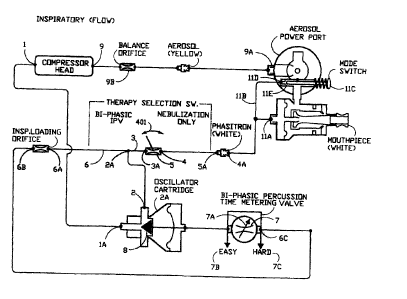
[0017] FIG. 9A diagrammatically illustrates the IPV breathing circuit; and
[0018] FIG. 9B is a standard Home Therapy HTTm Impulsator(10 breathing
circuit and FIG.
9C shows an alternative Phasitron Du0TM breathing head.
Summary
[0019] In summary, the present invention is a method and a system for
ventilating a patient's
airway during the inspiratory phase and expiratory phase from a source of gas
under pressure. The
system and method supplies, to the patient airway during the inspiratory
phase, a plurality of pulses
of small volumes of gas from said source of gas, and adds, in succession,
pulses of small volumes
of gas to provide successively greater volumes of gas successively increasing
in pulsatile form the
pressure of the gas in the airway of the patient during the inspiratory phase.
This addition adds
3
CA 02682427 2009-10-13
successively greater volumes of gas in the airway of the patient caused solely
by the successive
addition of the small volumes of gas and serves to provide diffusive
ventilation to the patient during
the inspiratory phase, and, permits the patient to exhale during the
expiratory phase. Further, a
smaller compressor set is used and the entire system is containerized in a
nylon, shock absorbing
travel bag.
[0020] It is important for the reader to know about chronic bronchitis and
obstructive lung
disease (COPD) and how their pulmonary systems can be damaged by incompatible
mechanical
ventilation of their lungs. This knowledge will advance the understanding of
the clinical
enhancements of a transportable Intrapulmonary Percussive Ventilation (IPV)
treatment apparatus,
allowing COPD and other home care patient's to travel, while having near
constant access to a light
weight travel oriented IPV therapy device enabling their daily multi scheduled
lung treatments.
[0021] Essentially a pneumatically controlled percussive higher frequency
pulsed breathing
device was created to enhance a medical treatment protocol called
Intrapulmonary Percussive
Ventilation IPV which can be used daily to recruit the diseased peripheral
pulmonary bronchioles
and alveoli of chronic bronchitis patients, with various partially or totally
obstructed bronchioles,
without airway damaging hyperinflation. Life supporting bronchioles and their
alveoli that remain
un-obstructed are called Preferential Airways, which if over-inflated during
mechanical lung
ventilation can be destroyed by hyperinflational barotraumas.
[0022] Essentially a pneumatically controlled percussive higher frequency
pulsed breathing
device called Intrapulmonary Percussive Ventilation IPV can be used during
multi scheduled daily
home treatments to recruit the diseased peripheral pulmonary bronchioles and
alveoli of patients
with chronic bronchitis and or other respiratory diseases, with various
partially or totally obstructed
4
CA 02682427 2009-10-13
bronchioles, without airway damaging hyperinflation. Life supporting
bronchioles and their alveoli
that remain un-obstructed are called PREFERENTIAL airways, which if over-
inflated during
mechanical lung ventilation can be destroyed by hyper-inflational barotraumas.
[0023] Typically, barotraumatic lung injuries are caused by lung
maintenance ventilators
programmed with a mandated volume-pressure limiting means of lung ventilation.
[0024] Thus, the novel Home Therapy (HTTm) Universal Bi-phasicTM IPV
IMPULSATOR delivers institutional quality, percussive higher frequency
smaller sub tidal
volumes in milliseconds, instead of volume oriented CMV ventilators with lower
cycled rates
delivering larger intrapulmonary Tidal Volumes into the lungs in seconds. The
smaller percussively
delivered sub tidal endobronchial volume deliveries in milliseconds provide a
Lung Protective
Strategy to prevent hyper-inflational barotraumas associated with larger
endobronchial Tidal
Volumes delivered into the lungs in seconds.
[0025] Patients with chronic COPD and acute peripheral lung diseases, have
multi degrees
of obstructive phenomena within their bronchiolar airways causing major
diffuse differences in
alveolar gas exchanges. Major components of these bronchiolar airway
obstructions are caused by
mucosal and sub mucosal edema within the walls of the airways, reducing their
internal diameters.
Additionally, mucus generated by the Goblet Cells lining the bronchiolar
airways, becomes thick
and tenacious causing increased airway obstruction because of airway secretion
retention. Most
important diffuse bronchiolar airways have various degrees of obstruction,
while other diffuse
bronchiolar airways are un-obstructed.
[0026] Generally the diseased bronchiolar airways have mixed degrees of
obstruction from
open to totally obstructed, the open bronchioles with the least inflow
resistance are called
CA 02682427 2009-10-13
"Preferential Airways", become overwhelmed by inflow during CMV ventilatory
protocols, as the
endobronchial delivery pressures rapidly increase; while attempting to deliver
a pre-selected
endobronchial Tidal Volume in seconds.
100271 This causes selected hyperinflation of the unobstructed
Preferential bronchioles and
the pulmonary alveoli they serve, leading to hyperinflational barotraumas to
the very dependent lung
that is providing life supporting, re-oxygenation functions.
[00281 Oxygen can be diffusively delivered into the peripheral pulmonary
airways during
the inspiratory inflation of the lungs with lesser tidal air exchanges than
recruiting and exhaling
Carbon Dioxide generated from metabolism, which is delivered into the
pulmonary alveoli and must
be "pumped" up out of the lungs to ambient by larger tidal breaths.
[0029] Dr. Bird's concepts for Intrapulmonary Percussive Ventilation
(IPVC) and
Volumetric Diffusive Respiration (VDRID) are based upon a higher rate of
percussive pulmonary
gas exchanges, while maintaining smaller sub tidal volume injections with
endobronchial injections
timed in milliseconds.
100301 Volume-pressure programmed mechanical lung ventilators deliver
large Tidal
Volumes "timed in seconds" under available selected peak endobronchial
delivery pressures, which
are primarily determined by the gross inflow resistances within the pulmonary
airways of the lungs.
This mechanical ventilatory program timed in seconds produces higher sustained
bronchiolar airway
pressures, which serve to hyperinflate the Preferential Bronchiolar Airways
having the least inflow
resistances. This type of volume-pressure mechanical lung ventilation (CMV)
can create
hyperinflational barotraumas, destroying the most functional lung tissues.
6
CA 02682427 2009-10-13
100311 Intrapulmonary Percussive Ventilation (IPV0) of the lungs delivers
a constant higher
frequency percussive delivery of air-bursts, consisting of small sub tidal
volumes into the lungs
within milliseconds; without the large lung distending Tidal Volume deliveries
of Volume-Pressure
limited (CMV) ventilators, which are "delivered in seconds".
100321 Thus I PV with higher frequency millisecond sub tidal pulmonary
ventilation allows
the patient to breathe spontaneously "at will" through the percussive sub
tidal volume deliveries,
without hyperinflation of the bronchiolar "PREFERENTIAL" airways.
100331 Patients with chronic bronchitis and other lung diseases can expand
their bronchiolar
airways and inflate their pulmonary alveoli at the peak of their spontaneous
inhalation. However,
the bronchiolar airways that are partially obstructed by bronchiolar wall
swelling and retained mucus
collapse during early exhalation, trapping gas in their pulmonary alveoli.
This causes their
bronchiolar airways and their dependent alveoli to be constantly partially
inflated during both
inhalation and exhalation, this is called "alveolar air trapping." Attached to
the outside walls of the
partially distended Bronchioles are the Bronchiolar blood vessels that
transport blood to nourish the
lung structures. In patient's with chronic bronchitis the stretched and
narrowed Bronchiolar blood
vessels; overtime, do not supply sufficient perfusion (blood flow) to the lung
structures, causing an
increasing ischemia (reduced blood supply) and final necrosis (deterioration)
of the peripheral lung
structures, similar to the typical end stage lung disease called "Pulmonary
Emphysema." Typically
Intrapulmonary Percussive Ventilation (IPVC) was conceived and designed to
recruit the
bronchioles and their dependent alveoli within COPD patient's lungs, who are
hospitalized with
acute pulmonary infections, creating further encroachment upon their existing
chronic lung diseases.
Without the lung protective strategies of I PV certain of this patient
population, if placed on
7
CA 02682427 2009-10-13
volume-pressure oriented mechanical (CMV) ventilators will develop
hyperinflational barotrauma.
The potential for acute pulmonary infections requiring hospitalization in this
COPD patient
population is some 2.7 times annually. The rational for the 2.7% rate
involvement is based upon the
fall cold season, the winter influenza period and a 7 percent chance of
patient's becoming infected
with summer chest colds.
[0034] There are millions of known COPD patients residing within the
United States and
many more overseas, who employ pharmaceuticals to ameliorate the symptoms of
their COPD
diseases, without prophylactically addressing the insidious loss of their
Bronchiolar (blood
supplying) circulations. Thus, over time an ischemic pulmonary Bronchiolar
blood supply develops,
which can ultimately serve to mandate an untimely Pulmonary Emphysematous
death.
[0035] Asthmatic patients have acute episodes of peripheral lung
obstructions, without the
constant hyperinflation of their bronchioles and alveoli. Whereas COPD
Patient's with chronic
bronchitis have constant unrelenting partial inflation of their bronchioles
and their dependent alveoli.
[0036] The constant partial inflation of the Bronchioles and their Alveoli
of patient's with
chronic Bronchitis etc. serves to stretch and narrow their Bronchiolar Blood
Vessels, which are
attached to the outer walls of the Bronchioles. Thus, the mechanical
stretching and narrowing of the
Bronchiolar blood vessels of the lung structures, creates an ischemic
reduction in perfusive blood
flow through the lung tissues.
[0037] The diffuse constant partial inflated condition of the peripheral
Bronchiolar airways
ultimately creates a necrosis leading to end stage lung disease called
Pulmonary Emphysema. Thus,
the Asthmatic with only infrequent acute bronchiolar and alveolar airway
obstructions, without the
constant unyielding interference with bronchiolar blood supply, do not loose
their Bronchiolar blood
8
CA 02682427 2009-10-13
supply causing the end stage lung disease called Pulmonary Emphysema.
Asthmatics rarely if ever
become Emphysemateous.
[0038] In the 1980's Dr. Bird had configured a hospital type IPV
Percussionator with
a self-contained air compressor for allowing patients with COPD to take daily
hospital quality IPV
treatments within their homes. Since that time thousands of home care
Impulsators have been
prescribed world wide for home care IPV treatments.
[0039] The overall results among these COPD patient populations
maintaining daily IPV
treatment schedules, have revealed; a very major decrease in acute pulmonary
infections, requiring
hospitalizations.
[0040] IPV patient's with beginning chronic bronchitis who have not
experienced notable
Bronchial circulation loss, appear to have minimal if any disease progression
if they maintain an
exact recommended IPV treatment schedule. Thus, it reasonably suggests that
with daily
scheduled IPV ID lung recruitments; the patients with beginning Chronic
Bronchitis are receiving
sufficient remission from Bronchiolar circulatory encroachment, to prevent the
expected insidious
loss of pulmonary tissue perfusion. In other words, IPV may therapeutically be
preventing the loss
of Bronchiolar circulation by multi daily lung recruitment, similar to the
Asthmatic patient with
extended periods of peripheral airway obstruction remissions.
[00411 Many home care patient's using the heavy Percussionaire Impulsator
, continue
to realize the prophylactic clinical efficacy of the IPV device. Patient
suggestions have revealed,
that many of these home care IPV patient's perceive that they are
therapeutically confined to their
locale because of the weight of their home care therapeutic Impulsator
devices, which do not lend
themselves to easy travel. With the number of COPD patient's rapidly
increasing, Dr. Bird
9
CA 02682427 2009-10-13
attempted to conceptively maintain or advance the clinical efficacy of the
present heavy IPV
Impulsatort; by conceiving combining methodologies, enabling the application
of a novel light
weight air compressor with lesser air volumes at lower pressures, to provide
for a transportable
therapeutic IPV system. Compare the smaller, lighter compressor set in the
foreground of FIG.
to the larger compressor set in the background.
[0042] Novel methodologies were required to create a percussive IPV
therapeutic
endobronchial impaction equal to or better than the existing heavy Impulsator
technology; while
employing some one quarter of the current air volume used while maintaining
traditional
institutional IPV clinical efficacy, were integrated into novel design. Thus
the pneumatic oscillator
circuitry and integrated Phasitron patient interface had to be integrated to
maintain the percussive
impaction qualities within the cyclic IPV frequency ranges of the existing
heavy 1mpulsator .
[0043] Design configuration required the innovation of a novel pneumatic
oscillation
circuitry using a vastly decreased air supply volume, with controlled
thermodynamic packaging; to
maintain effective environmental compressor cooling within an encapsulating
housing; while
configuring a condensing temperature drop to cause water condensation beyond
the oscillator
circuitry.
[0044] The volume of a deep drawn aluminum encapsulating housing 12, FIG.
3, with a
recessed cover to serve as a control panel, with a convective internal ambient
air flow through, had
to be determined to protect the IPV apparatus during routine patient travel.
[0045] The internal pneumatic oscillator circuitry and the integrated
external Phasitron had
to be innovated to provide manual control over cyclic frequency amplitude,
with a much reduced,
operational compressed air volume.
CA 02682427 2013-03-27
[0046] The following components were removed or significantly replaced from
the present heavy
Impulsator design: (a) Replaced the heavy high volume air compressor, with a
lighter lower
volume air compressor. (b) Removed the operational pressure-volume relieving
system. (c)
Removed the operational pressure gauge. (d) Removed the proximal airway
monitoring system. (e)
Removed the oscillatory timing circuit loading check valve. (f) Removed the
Phasitron loading
orifice. (g) Removed the external adjustable range calibration orifice.
[0047] The Home Therapy HTTm Impulsator0; air compressor oscillation circuit
and Phasitron
integration methodology are configured as follows:
1. Air from the compressor head outlet 1, in FIG. 1, is delivered directly
into the inlet of the
pneumatic oscillator cartridge 2A.
2. Air is directed from the outlet 2 of the Oscillator cartridge 2A into a
distribution Tee piece
with design controlled resistances to outflow.
3. One leg of the Tee piece is directed into the inlet of a two position
OFF-ON pneumatic
switch 5 with a graded resistance to outflow.
4. The OFF¨ON Therapy Selection pneumatic switch 5 has an outlet fitting 4
delivering pulsed
gas flows into the inlet of the Phasitron Primary Service socket 4A.
5. Note #1- The outflow resistances between the outlet 2 of the Oscillator
cartridge into the
Phasitron Secondary Service socket is regulated by design.
[0048] The OFF-ON pneumatic Therapy Selection switch 5, when in the
NEBULIZATION ONLY
position (see FIG. 2 switch position), interrupts the Oscillator cartridge 2A
pulsed gas deliveries to
the Phasitron Service socket thereby blocking pulsed air flows to the venturi
jet orifice 11A of the
Phasitron . Note #1- The Therapy Selection switch 5 functions are identified
by
11
CA 02682427 2013-03-27
the OFF and ON throws (arrow 401) on the switch stem, which are labeled as
follows: In the OFF
position, "NEBULIZATION ONLY." See FIG. 2. In the ON position, "Bi-phasicTM
IPV WITH
NEBULIZATION." See FIG. I. Note #2- When the Therapy Selection switch 5 is in
the OFF
NEBULIZER position, all outflow from the compressor is directed into the
nebulization circuit
leading to orifice 11A. See labels on switch 5 in FIG. 4.
[0049] The opposing leg 6 of the distribution Tee piece, is directed into the
inlet of an inspiratory
loading orifice 6A. The outflow from the inspiratory loading orifice 6B is
delivered into the
common inlet-outlet 6C of the time metering valve 7. Note #1- the inspiratory
loading orifice 7D in
FIG. 6 limits the rate at which the time metering valve air can upload the
oscillator cartridge
servoing chamber 7E in FIG. 6 to interrupt oscillator cartridge outflow,
essentially controlling the
limits of the interrupter valve opening time.
[0050] The rotary time metering valve control knob 7A in FIG. 6 with an index
arrow, is top
identified as "Bi-phasicTM PERCUSSION" with a 12:00 index labeled AVERAGE.
[0051] A left facing PERCUSSION control knob rotation toward EASY 78 in FIG.
1, (see "EASY"
label) increases the common up-down loading orifice size decreasing the time
required for up-
loading and down-loading. A right facing control knob rotation toward HARD
marker 7C decreases
the common percussion inflow/outflow orifice size increasing the time required
for uploading and
down-loading. Note #1- The up-loading pressure within the oscillator timing
circuit before flow
metering through the inspiratory loading orifice 7D in FIG. 6 would be the
same as the venturi jet
orifice pressure, which is controlled by the non regulated air compressor
operational delivery
pressure. Note #2- the percussion time metering orifice 7D in Fig 6 size will
control the rate at
which the interrupter cartridge servoing pressure chamber 7E in Fig 6 is up-
loaded,
12
CA 02682427 2013-03-27
interrupting outflow. It requires a greater servoing pressure chamber pressure
rise to close the
oscillator cartridge gate 7G in Fig 6 because of the opening pressure against
the diaphragm seal 7F
during the period the valve is open. Note #3- The down loading air, out-
flowing from the interrupter
cartridge valve servoing chamber 7E in Fig 6 exits to ambient through the un-
pressurized
Phasitron sliding venturi tube jet orifice 11 A in FIG. 1. Note #4- The rate
of air outflow from the
servoing chamber 7E (FIG. 6) of the oscillator cartridge 103 in FIG. 6 to re-
initiate inspiratory air
flow from the oscillator cartridge to the venturi jet orifice, will be longer
than the inspiratory flow
time because the opening pressure during valve open time, against the
oscillator cartridge
diaphragm seal 7F (Fig 6) is absent. Therefore, it will require a greater
servoing chamber 7E (Fig 6)
downloading air volume to allow the valve gate to re-open ending the
expiratory no flow time. Note
#5-The open-closing time (ratio) of the oscillator cartridge 103, FIG. 6 will
automatically vary from
near 1 to 1+ at the higher cycling rates to the slower cycling rates of 1 to 3
because of the
differentially required valve opening and closing pressures.
[0052] The clearance immediate opening of the interrupter valve gate 7G Fig 6
within the oscillator
cartridge 103 enables a maximum sub tidal volume transfer into the lungs
during a selected
inspiratory time, for a maximum sub tidal volume to be injected through the
Phasitron into the
physiological airways. It follows, that the closing of the interrupter
cartridge valve gate 7G must be
near instantaneous to allow an immediate opening pressure drop through the
Phasitron to ambient
allowing a maximum physiological gas outflow during the allowed expiratory
time. Note #1- Any
delay in the retraction (opening) of the Phasitron sliding venturi 102 in Fig
8A will cause an
increase in the residual sub tidal volume of gas remaining within the lungs,
creating a partial end
expiratory inflation of the pulmonary airways, called a design mandated
"Positive End Expiratory
13
CA 02682427 2009-10-13
Pressure" (PEEP). Designed PEEP can cause the partially inflated pulmonary
airways to stretch and
narrow the attached Pulmonary and Bronchiolar blood vessels decreasing blood
flow through the
lungs. This is why the integration of the Oscillator cartridge 103 in Fig 6 in
terms of cyclic flow
interruption of the Phasitron 101 in Figs 8A, 8B is of such critical
importance. Note #2- The
percussive sub tidal injection volumes and recovery from the pulmonary airways
has been enhanced
by a more rapid Phasitron opening and closing, enabled by decreasing
resistance within the
Oscillator cartridge timing circuit, to flow gradient reversals.
[0053] The constant unregulated air generation of the air compressor is
regulated by:
1. First, employing a constant ambient venting of compressed air flowing
through the
nebulizer jet orifice to ambient preventing a secondary residual compressed
air lock up
within the pneumatic circuits, which would prevent the compressor from
starting against a
residual outlet pressure.
2. Second, the Nebulizer is designed to generate aerosol over an expanded
inlet pressure
range without decreasing the clinical efficacy. Therefore, a balance orifice
9B in FIG. 1 is
employed to deliver excess systemic compressed air pressures and their related
volumes to
the nebulizer jet orifice 9A.
Note #1- When the oscillatory cartridge 103 in Fig 6, flow of pulsed air is
interrupted by
valve gate 7G, the systemic pressure to the nebulizer inlet port 9A in Fig 1
is increased,
increasing the volume of aerosol while limiting the systemic pressure rise.
Note #2- Thus, this novel means of operational pressure regulation is employed
to
effectively manage a limited air supply while maintaining selectable
percussive sub tidal
volume delivery amplitudes associated with the concomitant manufacture and
endobronchial
14
CA 02682427 2009-10-13
delivery of an appropriate aerosol particulate spectrum.
[0054] By
decreasing the piston stroke volume of the employed compressor; while
substantially increasing the compressional stroke volume compression rates, a
lesser excess air
volume can be design generated, eliminating the mandated venting of compressed
air pressure-
volumes to ambient. During each compressional stroke volume an "energy surge
spike" is created
during the overlapping compressional piston strokes. When excess gas volumes
are directly vented
to ambient by a pressure rise regulator the majority of the "pressure rise
energy spikes" are vented
to ambient. Note #1- In the Home Therapy HTIrm configuration, the "energy
surge spikes" created
by each compressional piston stroke are directed into the patient's proximal
pulmonary airway
during sub tidal volume deliveries by the Phasitront venturi jet orifice 11A
in Fig 1 as well as,
through the nebulizer jet orifice 9A serving to internally increase the
particulate diffusion during the
liquid to particle aerosolization process. Note #2- The sharp microsecond
generated "energy spikes"
attach themselves to the scheduled sub tidal volumes which serve as transport
vehicles for the
delivery of the energy spikes endobronchially during sub tidal volume
delivery. Note #3- The micro
energy spikes transported into the pulmonary airways during sub tidal volume
delivery, impact upon
the walls of the pulmonary airways decreasing their elastomeric expansional
resistance during
repetitive sub tidal volume deliveries. Note #4- The micro agitation within
the pulmonary airways
during each expansive microsecond sub tidal Volume delivery, ceases during the
expiratory distal-
proximal physiological outflow, providing for a more forceful elastomeric
contraction of the
pulmonary airways. Note #5- Thus, the more rapid the mechanical expansion and
physiological
elastomeric contraction of the pulmonary airways during the cyclic sub tidal
volume exchange, the
greater the directional "vesicular peristalsis augmentation" of the blood and
lymph flow though the
CA 02682427 2013-03-27
vessels attached to the exterior walls of the conducting vessels, thus
providing for an enhanced
intrapulmonary fluid flow.
[0055] The lower amplitude percussive sub tidal volume deliveries serve to
enhance endobronchial
diffusive gas mixing, favoring oxygen uptake. Note #1- A manual controlled
mode switch 11C in
FIG. 1 allows the patient to intuitively increase convective sub tidal
delivery amplitudes, favoring
carbon dioxide "wash out" from the lungs. This is periodically accomplished by
manually
increasing the Phasitron jet orifice operational pressures.
[0056] The following novel manual control over percussive (convective) sub
tidal volume
amplitude is created as follows:
1. A Tee piece inserted into the end of an approximate 48 inch interfacing
tubing bleeds air
from the Phasitron Service socket, out through the mode switch orifice 11D to
ambient. Line
11B diagrammatically illustrates the lengthy tube. The lengthy tubing (about
48 inches)
provides a convenient (remote) inter connection between the Phasitron service
socket 5A
and the inlet of the Phasitron 11A patient interface.
2. A thumb or digit actuated mode switch mechanical plunger 11C can close
orifice valve 11D
by applying a thumb pressure. The patient controls digit switch 11C with his
or her hand and
moves rod end 11E into and out of the valve orifice 11D.
3. When the pneumatic mode switch 11C is normally open, a certain amount of
the pulsatile.
Phasitron inflow is vented through a calculated orifice size to ambient,
decreasing the
Phasitron venturi jet pressure. This decreases the amplitude of the percussive
sub tidal
delivery into the lungs.
[0057] When the mode switch orifice 11D is manually closed by switch 11C, the
gas flow
16
CA 02682427 2009-10-13
to the Phasitron sliding venturi jet orifice 11A is increased, thus
increasing the percussive
amplitude of the endobronchial sub tidal volume delivery.
[0058] Note #1- The above Home Therapy HTTm novelty enables the patient to
create a
direct intuitive sinusoidal lung recruitment program without the manipulation
of the previous remote
operational pressure source and/or periodically adjusting the percussive time
constants, as was
previously required. The heavy Impulsator mode switch 11C was employed to
"interrupt
percussive oscillation" while continuing the endobronchial delivery of aerosol
generated by the
continuous nebulization functions. This leads to patients favoring periods of
nebulization at the
expense of therapeutic percussive lung recruitment.
[0059] Note #2- Another advantage of the present Oscillator-Phasitron
integration is the
elimination of the IPV calibration orifice previously controlling the
expiratory (down loading) i/e
ratio component (inspiratory to expiratory "i:e" ratio) of the out-flowing air
from the Oscillator
cartridge Servoing Chamber 7E in Fig 6.
[0060] Note #3- When the out-flow orifice of the heavy Impulsator was
obstructed by the
breathing head mode switch, oscillation was arrested providing for
nebulization only. Additionally,
the interfacing tubing interconnecting the removed 1PV calibration orifice
with the breathing head
mode switch was eliminated in the HTTm design.
17
CA 02682427 2009-10-13
[0061] Note #4- There are alternate types of mode switches used in two
types of Phasitron
breathing heads.
[0062] Note #5- The alternate Phasitron breathing head design employs an
ambient vented
mode switch orifice venting to ambient. When the mode switch orifice is
occluded by the patient's
Thumb the sub tidal volume amplitude is increased.
[0063] The entire self contained Home Therapy HTTm Impulsator apparatus
with the
limited pressure-volume air compressor 10 in Fig 3 is packaged within a deep
drawn aluminum
housing 12. The compressor 10 is shock mounted in housing 12 to provide
isolation and positioning.
An inserted top cover panel 12B, see FIG. 4, closes the open top of the
housing 12 (FIGs. 3, 4)
providing for a labeled control panel 12B for patient control access. Cover
top flap 12 BB, FIG. 4,
further protects the unit.
[0064] Note # 1- The environmental compressor thermodynamics within the
closed housing
are accommodated by the insertion of two fans 13A in Fig 3 within the aft wall
of the deep drawn
aluminum housing 12. One fan 13B forces an excess of ambient air into the
confines of the housing
12. The other fan 13C evacuates the confines of the housing, with sufficient
air exchange to control
the temperature drop of heated compressed air within the housing allowing
condensational cooling
outside the housing to prevent water accumulation within the internal
oscillation circuits.
[0065] A direct internal compressor driven shaft integrated fan 13D
provides for diffuse
internal circulation within the housing. The cooling fans employ the same
electrical power as the
compressor. Compressor 10 is mechanically powered by motor 12A shock mounted
in case 12.
[0066] Line power is delivered through a lower (grommeted) hole through the
left facing
side of the housing 12 by an attached and restrained power cord.
18
CA 02682427 2009-10-13
[0067] Note # 1- Adjacent to the power cord grommet are two vertically
spaced fuse holders
providing split power line protection. The internal wiring meets conventional
underwriters
standards.
[0068] Entrained air is drawn into the compressor through an ambient vented
exchangeable
filter 17 in Fig 4 positioned through the top of the control panel 12B.
[0069] The entire deep drawn aluminum housing 12 in Figs 3, 4, is dropped
into a top
loading, insulated airline quality nylon container bag 12C in Fig 4 with a
reinforced bottom and semi
snug fit. Straps 301, 302 and zipper closures 305 secure the unit in the
portable bag 12C. Other
closure systems may be used.
[0070] Appropriate holes are made through the walls of the nylon container
pack 12C to
accommodate the aft cooling fans, the left facing side accommodates the
electrical power inlet.
[0071] The containing transport pack is fastened to the aluminum housing 12
by installed
grommet type accommodations as well as, snap type fasteners. In this manner
bag 12C is securely
mounted on housing 12.
[0072] Accommodations for the Home Therapy HTTm Impulsator accessories are
managed
as follows:
1. A left facing side pocket 18A contains the power cord in Fig 4.
2. A front facing compartmented pocket 18B contains the interfacing tubing's
and
medications etc.
3. A right facing side pocket 18C contains the Phasitron Breathing head
assembly.
4. A left top-side attached zippered nylon fabric open top cover 12 BB with a
"zippered
inside compartment", provides for the storage of operational instructions etc.
19
CA 02682427 2009-10-13
[0073] The preceding data describes a novel self contained transportable
integrated medical
apparatus capable of providing institutional quality IPVID lung recruitment by
means of a unique
Intrapulmonary Percussive Ventilation (IPV ) Percussionator housed in a
typical transportable
airline pack. This device was conceived to allow present or new COPD patients
who now have or
are considering the heavy home care IPV Impulsators , which have been
clinically mandated for
use at least twice daily; to travel reliably wherever they elect to go with a
light weight portable
Home Therapy HTTm Impulsator IPV therapy device, without fear of being
separated from their
mandated daily home treatment schedules.
[0074] Medically and technically, the preceding information has described
novel alterations
to the basic IPV apparatus reducing the volume-pressure requirements for
compressed air volumes,
enabling the use of a much smaller, lighter and more transportable air
compressor while maintaining
the current "clinical efficacy of IPV using the heavy Impulsatore".
[0075] Conservation of energy providing for a limited volume of compressed
air has been
the determining consideration in the conceptual methodology employed to
develop a self contained
energy efficient transportable IPV device, while maintaining equal and/or
improved clinical
efficacy.
[0076] The rational for an extremely reliable analog percussive lung
ventilatory apparatus
for the physiological recruitment of peripheral cardiopulmonary
pathophysiological abnormalities
makes the present invention, superior to electronically servoed medical CMV
ventilators in terms
of functional operational reliability, component simplicity and clinical
efficacy while maintaining
a lung protective strategy.
CA 02682427 2009-10-13
[0077] Note #1- Most important, the flow rate of sub tidal gases being
delivered into the
pulmonary airways is continuously, and near instantaneously, varied, by
alternating intrapulmonary
pressure changes occurring within the lungs, which are regressively
transmitted back into the
"throat" of a venturi tube 103 in Fig 8, thus varying the unrestricted
entrainment ratios of 1:5 down
to obstructive outflows of 1:1+ depending upon intrapulmonary inflational
resistances. Thus, the
ever-changing intrapulmonary airway resistances to inflow serve to control the
instantaneous rate
at which the lungs are inflated, providing a physiological control over
intrapulmonary distending
pressures, designed to prevent hyperinflational barotraumas.
[0078] Note #2- Therefore, comparing the novel use of fluidic compressed
air energy for the
control of depressed cardiopulmonary functions to electronically or
mechanically programmed
volume-pressure (CMV) ventilators, is like comparing apples to oranges.
Specifications for
electronic pulmonary ventilators are written for lung ventilatory maintenance
and not peripheral lung
recruitment as well as "recruitive lung maintenance", while maintaining a lung
protective strategy.
[0079] Computerization experts are not expected to understand that the use
of advanced fluid
dynamics employing calibrational logic (without employing computerized
programming), in the
scheduling of the present innovative pneumatic cardiopulmonary therapeutic
devices.
Patho-Physiological Considerations
[0080] Intrapulmonary volume trauma, mechanically induced secondary to
pulmonary
airway hyper-expansional ventilatory CMV scheduling, which can be aggravated
by a Positive End
Expiratory Pressure (PEEP), has been incriminated by certain physician
physiologists, as being the
potential cause of alveolar septation. (Null et al. published the following:
"Nasal ventilation alters
mesenchymal cell turnover and improves alveolartization in preterm lambs." 208
August 15; 178
21
CA 02682427 2009-10-13
(4): 407-18 Epub 2008 June 12. PMD 18556628 (PubMed- indexed for Medicine))
has suggested
that premature lamb lungs experiencing periods of some 72 hours of continuous
elevated semi static
positive airway pressures demonstrated alveolar septation at post.
[0081]
Illustrations by Null et al. in PEER documental reviews show lung damage
caused
by a non invasive Continuous Positive Airway Pressure (CPAP) associated with
Intermittent
Mandatory Ventilation (IMV), could logically be imposing upon Bronchiolar
blood flow leading
to ischemic alveolar septation (lung damage). Other illustrations by Null
etal. show the non-invasive
IPV type
lung ventilation without noted septation, when using Oscillatory Percussive
Positive
Airway Pressure (OD-CPAP) [an IPV derivative] to simultaneously ventilate the
lungs without
imposing upon Bronchiolar blood flow.
[0082]
Positive End Expiratory Pressure (PEEP) advocates, who employ PEEP to increase
the Pulmonary Functional Residual Capacities (FRC) of the lungs have
challenged the opinions of
certain clinician-physiologists who have suggested that PEEP could potentiate
Bronchiolar and
Alveolar hyper-distention in patients with peripheral lung disease. The
inventor became involved
with Continuous Minimal Airway Pressures (CPAP) in the early 1970's by
conceiving the logic for
Demand CPAP, which could maintain a near constant minimal proximal to distal
pulmonary positive
airway pressures during spontaneous or controlled respiration. He has since
created a Demand
Oscillatory OD-CPAP concept limiting any potential impact upon the Bronchiolar
circulation.
[0083]
Relatively few pulmonary physicians rationalize that the Intrathoracic
Bronchial
Circulation, if challenged during long term mechanical ventilation, by a
constant elevated expiratory
baseline, can create a peripheral airway and alveolar ischemia, ultimately
terminating in necrotic
tissue. Many clinicians have become so dependent upon PEEP in the apneic
patient and CPAP in
22
CA 02682427 2009-10-13
the patient without peripheral airway disease (in the spontaneous breathing
patient in terms of Pa02
enhancement) that the basic pathophysiology of COPD (chronic obstructive
peripheral lung disease)
may become shaded.
[0084] Clinical alveolar septation can be demonstrated in animal
experiments when a long
term continuous proximal-distal airway pressure gradient is maintained with or
without limited
mandatory intrapulmonary tidal exchange, during spontaneous respiration. This
observation may
in part demonstrate that without an adequate percussive physiological or
mechanical enhancement,
to the three intrathoracic circulations by physiological or mechanical means,
such as induced
"Pulmonary Vesicular Peristalsis" the bronchial circulation is continuously
impaired by partially
inflated peripheral airways and their alveoli, serving to stretch and
partially narrow the caliber of
the Bronchial circulatory vessels, thus creating a long term ischemic trend.
[0085] The inventor's concept of Intrapulmonary Percussive Ventilation IPV
with
associated mechanically created "Intrapulmonary Vesicular Peristalsis", has
served to enhance
intrathoracic directional vesicular blood and lymph flow.
[0086] The IPV concept was directed toward providing a recruiting
percussive sub tidal
gas exchange into and within the respiratory bronchioles and associated
alveolar structures, while
providing for a lung protective strategy. Thus the inventor's concept was to
mechanically provide
for peripheral lung recruitment while minimizing the potential for induced
barotrauma.
[0087] Equally important is the production ofa uni-directional "Vesicular
Peristalsis" within
the three intrathoracic circulations, namely the Bronchial, Pulmonary and
Lymph circulations.
"Vesicular Peristalsis" is dependent upon having the proximal airway vented
without restriction, to
ambient during the repetitive milli-second expiratory phases of sub tidal
endobronchial gas
exchange.
23
CA 02682427 2009-10-13
[0088] Before the near collapse of the supporting positive bronchiolar
airway pressures and
before the peripherally congested pulmonary airways depressurize and contract
toward their
obstructive positions, the next controlled percussive inspiratory sub tidal
volume is mechanically
delivered endobronchially, to re-inflate the contracting bronchiolar airways
and deflating pulmonary
alveoli. Therefore, the entire tracheobronchial tree receives continuous
peristaltic directional
pulsatile stroking waves from the trachea into the peripheral bronchiolar
airways, during
programmed sub tidal volume delivery intervals. As the pulmonary airways are
mechanically caused
to cyclically contract and expand, the attached vessels of all three
intrathoracic circulations are
repeatedly peristaltically compressed and released, during the cyclic
expansion and contraction of
the pulmonary airways to which they are attached.
[0089] Thus, the inventor's concept of Intrapulmonary Percussive
Ventilation IPV serves
as a lung recruitment means by the percussive intrapulmonary gas mixing and
gas exchange as well
as, enhancing the directional vesicular flow of fluids flowing through the
three intrathoracic
circulations, thus enhancing a mechanically induced "Vesicular Peristalsis".
[0090] Another PEER supporting article is by Schiller, (Effect of positive
end ¨expiratory
pressure and tidal volume on lung injury induced by alveolar instability,
Critical Care 2007, 11:R20
et al., in Critical. Care Medicine, 2001; 29:1049) discusses and shows the
acute respiratory distress
syndrome ("ARDS") lung (at 100 magnification), is associated with lowered
surface tensions,
mucosal and sub mucosal edema, retained endobronchial secretions and
bronchiolar spasm, which
can all lead to alveolar over distension in the destabilized ARDS lung,
secondary to "Preferential
Airway" related alveolar hyper distension associated with volume-pressure
oriented (CMV) lung
maintenance ventilators.
24
CA 02682427 2013-03-27
[0091] Thus, it may be further illustrated that Preferential hyper volume
induced pulmonary
barotraumas may well be created by volume-pressure (CMV) limiting techniques
in patients with
obstructive peripheral lung encroachment (disease) however caused. (Gary
Neiman et al., Upstate
Medical Center, New York University published- "Injurious mechanical
ventilation in the normal
lung causes a progressive pathologic change in dynamic alveolar mechanics."
Critical Care
2007:R64).
[0092] Gary Nieman's clinical finding have again shown by using unique living
mammalian lung
models volume-pressure limited continuous mechanical pulmonary ventilation
(CMV) is tolerated
in near normal pulmonary structures (lungs). However, when the peripheral
pulmonary airways
(bronchioles etc.) serving alveolar structures become unevenly diffusely
encroached upon by
mucosal and sub mucosal edema, retained endobronchial secretions, bronchiolar
spasm as well as
other factors, the three intrathoracic circulations can be progressively
encroached upon leading to
ischemia and ultimately non reversible necrotic alterations such as various
forms of respiratory
distress syndromes and end stage diffuse obstructive pulmonary emphysema.
[0093] While current medical research continues to support the clinical
efficacy of Intrapulmonary
Percussive Ventilation IPV advancing research reveals that technological
novelty can further
facilitate the clinical efficacy of the Intrapulmonary Percussive Ventilation
IPV and Volumetric
Diffusive Respiration VDR protocols, by applying innovative rationales.
Primary Revelations, Supporting Technological and Clinical Data
[0094] Certain functional, therapeutic, administering protocols, and methods
are set fourth in: (a)
Ventilator Having an Oscillatory Inspiration Phase and Method, U.S. Patent No.
5,862,802; (b)
Apparatus for Administering
CA 02682427 2013-03-27
Intermittent Percussive Ventilation and Unitary Breathing Head Assembly for
Use Therein, U.S.
Patent No. 6,595,203; (c) Interface Apparatus and Combination and Method for
use with a
continuous Volume-Pressure (CMV) ventilator and an Intrapulmonary Percussive
Ventilator and
Combination thereof and the IPV - VDR associated embodiments set forth in
U.S. Patent No.
6,581,600 B2.
[0095] The current Intrapulmonary Percussive Ventilation IPV heavy Impulsator
is semi
portable and has a self-contained IPV Percussionator device with an internal
high
volume/pressure air compressor 10 weighing about 18 pounds (compressor-motor
unit) see FIG. 4,
foreground compressor set, capable of generating some 90 psi. The overcapacity
air-flow of the
heavy Impulsator is regulated with a pressure reduction regulator monitored
by an operational
pressure gauge. Normal selected operational pressures are from 25 to 55 psig.
The higher generated
flow pressures are vented to ambient by a pneumatic pressure-regulating
device.
[0096] The definition of an intra pulmonary induced "Sub tidal volume
exchange" is the cyclic
percussive pulmonary airway injection of an air volume, which is less than the
total patient's
"Physiological Dead Space" (where a blood gas exchange interface does not
exist).
[0097] In order to obtain a sharp percussive impulse during sub tidal volume
injection, the selected
injection (the Ram Pressure) must be adequately maintained.
[0098] The generation and endobronchial delivery of aerosol particles
(nebulization) is continuous
during percussive higher frequency oscillation or spontaneous respiration
provided by the
compressed air output flow/pressure, which can be regulated by restrictive
multi orifice integration.
26
CA 02682427 2009-10-13
[0099] Intrapulmonary percussion is generated, by the controlled cyclic
(full opening and
closing) of a normally open pneumatic oscillatory flow/timing cartridge timed
in milliseconds. The
selected regulated operational pressure during flow demand is generated by a
high rpm stroke
volume delivery (some 3500 rpm) with a calculated overlapping piston stroke
volume sufficient to
provide for the mandated flow/pressure demand of the 1PV apparatus. The
overlapping pulsatile
cumulative compressor stroke volumes create an "Energy Spike" during each
stroke, during the
repetitive flow/pressure generated volume accumulation, which is super-imposed
upon each sub
tidal endobronchial delivery. Compressor created air inflow is internally
interrupted by a flow
interrupter Oscillator cartridge, oscillating at selected cycling rates (in
milliseconds), usually from
about 100 to 500 cycles per minute.
[0100] Cyclic flow interruptions are designed to automatically produce
optimal near
instantaneous opening and closing, inspiratory-to-expiratory flow gradients
with "i/e" ratios of from
1:1+ at the higher selected frequencies down to 1:3 at the lower scheduled
frequency selections,
which are calibrated to maintain the patient's near normal functional residual
capacity (FRC).
[0101] FIGs. 8A, 8B show a physical-physiological proximal airway-
interfacing device
called a PHASITRON 101 which serves as a percussive proximal airway located
injector/exhalation valve, essentially serving as a pulmonary airway
interfacing respirator. The
PHASITRONS airway-interfacing device contains a sliding venturi tube-jet
assembly 102 for
endobronchial sub tidal air injection, as well as expiratory ambient venting,
of the entire proximal
pulmonary airways. The oscillator cartridge 103 delivers percussive gas
impulses (in milliseconds)
into the venturi jet inlet orifice 11A in Fig 1 of the Phasitron (airway-
interfacing device). The
27
CA 02682427 2009-10-13
opening and closing i/e ratios of the Oscillator cartridge 103 in Fig 6 are
controlled by pressure
differentials created by servoing pressures across a configured diaphragm seal
7F.
[0102] The Closed (Pressurized) Phasitron sliding venturi 103 in Fig 8B
shows a physical-
physiological proximal airway interfacing device which is servoed by the
Oscillator cartridge 103
in Fig 6 which delivers percussive bursts of air (in milliseconds) into the
venturi jet orifice inlet 11A
of Fig 1 of the Phasitron (airway-interfacing device). The opening and
closing i/e ratios of the
oscillator cartridge 103 in Fig 6 are controlled by designed pressure
differentials.
[0103] A pneumatic digit (finger-thumb) controlled manually operated
"normally open"
mode switch 11C in Fig 1 and mode switch orifice 11D, are located atop the
nebulizer. When the
digitally operated mode switch 11C is not depressed, (venting the mode switch
orifice to ambient)
a component of the air routed to the Phasitron venturi jet orifice is bled to
ambient, through the
mode switch orifice 11D, creating a flow-pressure decreases to the venturi and
nebulizer jet orifices.
Thus, causing the amplitude of the scheduled sub tidal volume delivery to be
decreased. When the
mode switch button 11C is manually depressed, arresting the ambient air bleed,
the pressure to the
venturi jet and nebulizer orifices are increased, which increases the
amplitude of the endobronchial
sub tidal volume deliveries. The mouthpiece outlet of the Phasitron airway-
interfacing device
must be sealed by the patient's lips for repetitive, percussive sub tidal air
volumes to be injected into
the airways of the lungs. Other means to connect the Phasitron outlet to the
patient airways such
as masks and indwelling airway tubes can be electively used.
[0104] The waveform FIG. 7 demonstrates that a sinusoidal waveformat can
be created when
the patient systematically depresses and releases the mode switch, creating a
Bi-phasicTM sinusoidal
high-low amplitude percussive oscillation, during the delivery of the selected
periodic sub tidal
28
CA 02682427 2009-10-13
endobronchial deliveries. If the patient so elects, they can spontaneously
breathe though the
scheduled percussive oscillatory program. Spontaneous breathing would decrease
the peak
oscillatory pressure rise during inhalation and increase the peak oscillatory
pressure rise during
exhalation, within the limits of venturi jet orifice inflows.
[0105] The percussive near instantaneous opening and closing of the
oscillator (flow- timing)
cartridge 103 in Fig 6 is a factor of design. The percussive oscillatory
cartridge opening- (flow) and
closing- (no flow) time are controlled by reversing flow through the common up-
loading and down-
loading time metering valve inlet orifice 6C in FIG. 1. The time metering
valve orifice 7D with
calibrated rotation is labeled from EASY at mark 7B to HARD at mark 7C.
[0106] The Intrapulmonary Percussive Ventilation IPV concept step inflates
the lungs to
a full ambient venturi flow/pressure clutching, called "oscillatory
equilibrium". See waveform, FIG.
7.
[0107] The oscillatory pressure rise (amplitude) is determined by patient
activation of the
mode switch 11C. The clinical management of obstructive pulmonary disease is
classically directed
toward the recruitment and maintenance of the bronchiolar airway patency
(size), which is limited
by mucosal and sub mucosal edema as well as, retained endobronchial secretions
and smooth muscle
spasm, diffusely imposing upon alveolar gas exchange.
[0108] Patients using the heavy Impulsator on a daily schedule for lung
recruitment could
consider the light-weight Home Therapy HTTm Impulsator with the novel patient
controlled Bi-
pFiasicTM therapeutic means, if they desire to travel while maintaining
clinical treatment efficacy.
Home patients who depend upon their heavy IPV Impulsator must consider their
life style. If they
29
CA 02682427 2009-10-13
feel "tied down" and have the desire to travel the Home Therapy HTTm
Impulsator may be an ideal
choice.
[0109] Some
of the therapeutic treatment mandates of the heavy Percussionator generally
favoring the novelization employed in the light-weight Impulsator are:
1. The existing 25+ pound weight of the heavy Impulsator may require
logistical
assistance to the semi invalid patient.
2. Setting up the existing (airway-interfacing device) Phasitron breathing
head with the
four (4) interfacing tubing requirements as opposed to two with the Home
Therapy HTI'm
Impulsator design.
3. Pulmonary disease treatment protocols should consider the existing self
contained heavy
Impulsaior in comparison to the light weight Home Therapy HTTm Impulsator
with the
novel patient controlled Bi-phasicTM therapeutic means.
4. Selecting the proper operating pressure for patient size and patho-
physiology.
5. Selecting the recommended percussion cycling frequency.
6. Teaching the patient to maintain a lip seal around the mouth-piece without
nasal venting.
7. Establishing a peripheral pulmonary airway mobilization program followed by
alternating
lung recruitment scheduling.
8. Instructing the patient to manipulate cycling frequency and impaction
forces to ventilate,
mobilize and then raise their retained endobronchial secretions, while
delivering medications
to reduce the intra airway swelling and enhance secretion mobilization, by
recognizing the
manual manipulation of operational pressures, percussive frequency and
percussive sub tidal
delivery forces.
CA 02682427 2009-10-13
9. Teaching the patient how to program the operational pressure selection and
monitor the
operational pressure gauge.
10. Teaching the patient how to interpolate the proximal airway pressure
manometer.
11. The patient can be expected to deviate from effective therapeutic
percussive therapy
protocols (not following prescribed orders) by selecting an operational
pressure below
clinical effective peripheral airway impaction pressures.
101101 patient must manually select NEBULIZATION therapy without lung
recruiting sub
tidal volume deliveries. This feature favors the patient maintaining the more
effective Bi-phasicTM
lung recruitment schedules.
101111 Improved Clinical Efficiency provided by the Home Therapy HTTm
Impulsator
101121 The following data highlights areas where the application of the
novel Home Therapy
HTTm Impulsator for travel, with technology directed toward actually
improving overall clinical
IPV efficiency, may present a greater patient intuitiveness.
I. The present heavy IMPULSATOR0, weighing over some 25 pounds, may be
difficult
for a semi invalid patient to carry during transport, eighteen pounds of which
is the weight
of the air compressor.
2. If the device is dropped, the heavy compressor acts as an internal
battering ram to
dislocate the compressor from the shock mounting case attachments.
Additionally, if it were
to fall upon a patient's legs, toes etc. serious injury could result.
3. The heavy Impulsator mandates a high volume compressor capable of
maintaining
selectable operational pressures o f up to 55 psi to maintain the selected
repetitive percussive
sub tidal endobronchial volume impulse.
31
CA 02682427 2009-10-13
4. The heavy Impulsator air compressor is noisy (like a vacuum cleaner). In
order to limit
compressional noise levels for appreciable noise reduction, while providing
for adequate
compressor head surface fan cooling, the present heavy Impulsator housing
would have
to be considerably enlarged, further limiting logistics.
5. The current heavy Impulsator device allows the patient too much access to
therapeutic
programming enabling deviation from the most effective clinical protocols,
which may be
based upon lack of clinical knowledge by those who prescribe the therapy to
the patient.
The Air Compressor System
[0113] Resolving certain mechanical and clinical limitations of the current
logistical state
of the art must first address the air compressor. Considerations directed
toward increased levels of
clinical efficacy and operational convenience and intuitiveness may consider
the following:
1. Selecting an appropriate air compressor must consider; air output,
weight,
operational power limitations, noise, compressional water condensation,
operational
cooling, oscillatory impaction associated with instantaneous demand pressure
drop,
operational reliability and functional longevity.
2. The novel methodology addressing the compressed air management system
and
operational means, can reduce the compressor mass to less than about one
fourth of
the present bulk and weight with less compressional heating, with a major
operational sound reduction. FIG. 5 shows the smaller compressor set used in
the
present invention in the fore ground and the larger prior art compressor set
behind
the smaller set.
32
CA 02682427 2009-10-13
3. The selection of an air compressor with a smaller diameter piston with
less volume
than the current larger piston air compressors, capable of developing an equal
or near
equal operational demand flow/pressure generation through an increase in
compressional stroke rates. This was accomplished by increasing the rate of
compressive strokes to some two to three times the current compressive
delivery
rates.
3. By limiting plumbing flow obstructions (restrictions) such as flow
through acute
angled fittings and restrictive tubing, a pressure reduction regulator, ON/OFF
switch
etc.
[0114] The Home Therapy HTTm Impulsator has two separate interfacing
oscillator and
nebulizer outlet Service sockets appropriately labeled for the user as BI-
PHASIC and NEBULIZER.
These labels are adjacent service ports in FIG. 4.
[0115] The first compressor head outlet fitting 1 directs outflow directly
into the Oscillator
cartridge inlet 1A. The second compressor head outlet fitting 9 provides for
the continuous flow-
pressure demand of the nebulizer through a flow-pressure balance orifice 9B
additionally serving
to balance the preferential flow into the Phasitron venturi jet orifice.
1. The total air generating output of the dynamic compressor must be
balanced against:
the Phasitron venturi jet and the nebulizer jet orifices, to provide for the
rapid
systemic pressure changes when the amplitude of oscillation is changed by the
patient.
33
CA 02682427 2009-10-13
2. The two flow balancing orifices 9A of the nebulizer and 11A of the
Phasitron
venturi jet orifices are calibrated such that a selected percussive cycling
pressure
impulse produces sufficient preferential percussive impaction to recruit
congested
peripheral pulmonary airways. Peripheral pulmonary airway flow must be
concomitantly aerosolized with a controlled nebulizer particulate generation.
3. Flow-pressure demands for both functions must be accommodated within the
maximum output flow-pressure limits of the compressor without a dedicated
reservoir.
4. Venting of the compressor head nebulizer outlet to ambient through the
nebulizer jet
orifice 9A will immediately release residual head pressures to ambient thus
negating
attempted starting against a compressed air load.
5. A leg of a Tee piece directs unrestricted flow from the outlet of the
oscillator flow
interrupter cartridge 2A through a Therapy Selection switch 5 to the orifice
inlet 11A
of the Phasitron venturi jet orifice. Switch 5 is user-labeled "Bi-Phasic
IPV" and,
in its opposite position, "NEBULIZATION ONLY." See FIG. 1 and FIG. 4.
2. A lengthy tubing (about 48 inches) provides a convenience (remote)
inter connection
between the Phasitron service socket 5A and the inlet of the Phasitron 11A
patient interface.
[0116] A pneumatic flow timing valve assembly, controls the timing of the
pulsatile systemic
air-flows forming an oscillatory circuit with adjustable cycling rates. This
is accomplished by
delivering oscillator cartridge outlet air 2 through a Therapy Selection
switch 5, through a
34
CA 02682427 2009-10-13
Phasitron Service socket 5A then delivering the pulsatile sub tidal air flows
through an extended
tubing to the Phasitron jet orifice 11A.
[0117] The uploading of the oscillator cartridge 2A, see also 103 in FIG.
6, servoing
chamber 7E in FIG. 6 pressurizes the oscillator servo diaphragm. Upon
pressurization the diaphragm
moves a valve stem forward effectively closing the valve gate 7G producing a
"no flow" condition.
[0118] Following servo chamber uploading with associated timing circuit
flow interruption,
the diaphragm servoing chamber down loads reciprocally through the common up-
down loading
time metering valve orifice 7, depressurizing the diaphragm thus causing the
re-opening of the
oscillator cartridge valve 8 in Fig 1.
[0119] The higher mandated reciprocal uploading pressure than downloading
pressure
against the common time metering valve orifice 6C, creates a shorter up
loading (valve open time)
than down loading valve closed time, automatically programming a neutral or
longer valve closed
time. This is called the opening-closing pressure differential or i/e ratio.
[0120] Upon valve closure "no flow" the reversing down loading air flows to
ambient
through the common up and down loading and unloading time orifice, creating an
equal to or longer
down loading (valve closing) time than up loading time (because of the
differential up and down
loading pressures, mandating a longer "no flow" (expiratory) time.
[0121] Higher sub tidal cycling rates are created by, selecting a larger
common orifice
causing a more rapid up loading as well as proportionately longer down loading
time. The opposite
obtains. The differential in a constant uploading pressure to a decaying down
loading pressure
mandates a neutral or positive i/e ratio. Thus, because of the larger common
selected orifice at
CA 02682427 2009-10-13
higher cycling rates, as opposed to a smaller common selected orifice at lower
cycling rates the i/e
ratios remain neutral or positive.
[0122] Following servo chamber bleed down causing oscillator cartridge
valve opening 8
in Fig 1 and the delivery of uploading air into the inlet of the time metering
valve as well as the inlet
of the Phasitron venturi jet orifice 11 A, up-loading begins. Because of the
pressure against the
diaphragm seal 7F in Fig 6 during valve opening, it will require a greater
uploading pressure to close
the valve than required for down loading. Thus down loading will require a
longer bleed down time,
increasing the expiratory time (valve closed) as compared to inspiratory time
(valve open). The
common time metering valve orifice 6C in Fig 1 primarily down-loads through
the inspiratory
loading orifice (when the therapy selection switch is in the Bi-phasic IPV
position) through the
cyclically deactivated Phasitron venturi jet orifice.
[0123] The remote patient operated mode switch 11C controls the amplitude
of a selected
percussive oscillatory cycling frequency. With the mode switch not depressed
part of the periodic
inspiratory flow directed into the Phasitron venturi jet orifice is vented to
ambient, decreasing the
amplitude of the selected sub tidal volume injection. When the patient
depresses the mode switch
button 11C, the ambient bleed of part of the venturi jet flow is interrupted
causing a pressure rise
in the Phasitron venturi jet and nebulizer orifices. This increases the
amplitude of sub tidal volume
delivery.
[0124] When the therapy selection switch interrupts flow to the Phasitron
venturi jet
orifice, oscillation ceases with the total systemic flow directed through
balance orifice 9B into the
nebulizer inlet 9A causing an increase in the nebulization pressure, which
increases the rate of
aerosolization. When the therapy selection switch is moved to the Bi-phasicTM
IPV position the
36
CA 02682427 2009-10-13
oscillation circuit is reactivated which reduces the systemic pressure to the
nebulizer (slightly
reducing the nebulizer output) while re-activating the venturi jet sub tidal
volume deliveries.
101251 The initiating resistance to Phasitron jet orifice inflow through
the therapy selection
switch 5 creates a gradual initiating sub tidal volume delivery, preventing an
initial hard
endobronchial impaction during the injection of the intrapulmonary sub tidal
volume.
101261 The following data provides for an improved understanding of the
novel patient
controlled Bi-phasicTM percussive amplitude intervals:
1. The mode switch orifice restricts the ambient venting of the
Phasitron venturi jet
orifice bleed air to ambient. When mode switch 11C is open (not depressed) the
flow
of air to the venturi and nebulizer jet orifices is decreased, creating a
decrease in sub
tidal delivery amplitude.
3. Peak percussive impaction amplitudes (for peripheral airway lung
recruitment) are
generated by not bleeding the Phasitron jet orifice air to ambient, during
sub tidal
endobronchial deliveries.
4. An approximate 48 inch interfacing tubing receives (pulsatile) sub tidal
volumes of
air from the Phasitron Service socket delivering into the Phasitron venturi
jet
orifice. The Phasitron inlet Tee piece is interconnected to the mode switch
orifice
8A in Fig 1. The mode switch orifice 11D Meters bleed air-flow to ambient
through
the normally open mode switch 11C.
5. The initiating nebulizer power interfacing tubing connects into the
Aerosol Service
socket. The other end of the nebulizer interfacing tubing interconnects into
the
Aerosol Power Port 9A.
37
CA 02682427 2009-10-13
6. By depressing the mode switch button the patient can interrupt bleed air
through the
mode switch orifice to ambient, increasing the pressure to both the venturi
and
nebulizer jet orifices. This increases the sub tidal delivery amplitudes while
concomitantly increasing nebulizer jet orifice flow.
6. Percussive impaction rates and associated amplitudes can be factory
calibrated up
or down, within clinical limits, by calibrating the Balance Orifice
controlling
nebulizer jet orifice flow.
7. The "Bi-phasicTM Percussion" time metering valve control knob Arrow,
allows the
manual selection of cyclic sub tidal volume delivery rates. Control knob
labeling
consists of EASY 7B which means a rapid low amplitude sub tidal volume
delivery,
HARD 7C which means a lengthened, high amplitude sub tidal volume delivery and
AVERAGE which can mean a clinically effective sub tidal volume delivery.
8. The (airway-interfacing device) Phasitron venturi air injection
velocities are
sufficiently high at any cycling rate selection (with a circular mouth piece
diameter)
to direct a conic sub tidal volume injection into the physiological airways
reducing
the lip pressure required to essentially seal the mouthpiece with the lips, to
minimize
physiological ambient leakage.
9. Clinically the patient is allowed to manually schedule therapeutically
effective
percussive amplitudes, to mobilize and recruit the peripheral pulmonary
airways with
a Bi-phasicTM sub tidal mandated minimal and maximal impaction.
38
CA 02682427 2009-10-13
10. For neonatal use and patient initiation only, the Bi-phasicTM
percussive amplitude
can be reduced to lower impaction levels by manually removing the pressure
monitoring plug (spoiler) near the outlet port of the Phasitron respirator
interface.
11. A bracket stored within the right facing travel pack pocket when
installed, allows the
patient positioning means for the breathing head.
12. Therefore, with manual thumb control over the Bi-phasicTM mode switch
the patient
has total single thumb (optional) control over the mobilization and
recruitment of the
Bronchial airway caliber as well as, the clearance of mobilized peripheral
airway
secretions. This is accomplished by employing a manual controlled Bi-phasicTM
oscillatory lung percussion to mobilize and recruit the airways without
manipulation
of several other traditional control media.
Review of Applied Technology
101271 An air compressor pack weighing some one-quarter of the existing
heavy
Impulsator air compressor providing for effective repetitive oscillatory
higher velocity percussive
sub tidal volume injections required for percussive IPV required the
following innovations:
1. By using a much smaller compressional piston area with an adjusted
stroke, requiring
much less motivational motor force during the compressional upstroke, to
generate
operational demand pressures with a lesser stroke volume at higher delivery
frequencies a novel IPV apparatus was created. In comparison, the heavy
Impulsator uses a low rpm (large piston) high mass weight (about 18 pound)
compressed air source to provide sufficient pneumatic energy for IPV versus
the
39
CA 02682427 2009-10-13
high RPM (small piston) air compressor, with a low mass weight of about (6.5
pounds).
2. Increasing the rate of compressional strokes in a unit of time
creates a ratio between
the maximum expected endobronchial sub tidal delivery rate and the number of
compression strokes per minute. For example; with the delivery of 500 sub
tidal
volumes per minute divided into the number of compression strokes of up to
about
3500 strokes per minute, there would be about seven (7) air compression
strokes for
=
each sub tidal volume injected into the patient's pulmonary airways, at the
maximum
anticipated pulmonary sub tidal volume delivery rate of 500-650 cycles per
minute.
Each up stroke produces a millisecond "energy spike" which is transported into
the
airways of the lungs to assist in pulmonary airway inflation during the sub
tidal
volume deliveries.
[0128] The current (state of the art) heavy IMPULSATORO air compressor
uses a
substantial piston area creating a higher stroke compression volume then
necessary for the required
air generating demand mandating higher power demand and mass than necessary
for the application.
[0129] With novel comprehensive applications of technology innovating an
existing IPV
apparatus a much reduced compressional air volume demand can be satisfied by
an air compressor
with considerably less piston area (reducing stroke volumes), by increasing
the rate of compressional
stroke volume deliveries required to satisfy the operational pneumatic energy
demands for an
effective Intrapulmonary Percussive Ventilation IPV
[0130] Each percussive endobronchial sub tidal volume delivery serves as
an intrapulmonary
transmission vehicle to be modulated by the micro compressional "energy
spikes" (shock waves),
CA 02682427 2009-10-13
created by each compressive piston upstroke. Thus the greater the rate of
compressive stroke volume
injections the greater the potential for endobronchial wall "micro agitation".
[0131] An increased temperature created by friction and air compression
serves to near
sterilize the compressed air. As the frictionally heated compressed air
rapidly cools beyond the
outlet of the oscillator cartridge, the near sterile water condensation is
vented predominantly through
the venturi jet orifice partially humidifying the endobronchial sub tidal
volume deliveries.
[0132] Thus, the thermodynamic control over the internal heat dissipation
(compressor
cooling), is designed to prevent water condensation within the Oscillator
cartridge and associated
flow-timing components.
[0133] Percussive sub tidal volumes are further augmented by modifying the
effective
(airway-interfacing device) Phasitron venturi flow-pressure entrainment
ratios by increasing the
velocity and volume of flow from the venturi jet orifice through the venturi
aspirational throat
geometry.
[0134] By computing the maximum required compressed air volume
requirements with a
functional oscillatory band width of from about 100 to 500, intra-airway sub
tidal injection strokes
per minute, will create i/e ratios of about 1:2.5 which will require the
maintenance of operational
pressures of from 30 to 35 psi.
[0135] The continuous mandated systemic flow, pressure, volume air
generation for
repetitive endobronchial percussive sub tidal volume injections, can be
controlled by balancing any
excess compressor generated air volumes through the nebulizer aerosol
generating jet orifice.
[0136] The nebulizer is capable of generating therapeutic aerosol volumes
far beyond that
required for peripheral lung particulate deposition. Thus, the variations in
excessive delivery of
41
CA 02682427 2009-10-13
aerosol beyond optimal endobronchial airway requirements are used to balance
the systemic
operational pressures are of little, if any clinical consequence.
[0137] By balancing the augmentation of compressed air generation, a
lesser air compressor
output complies with the design of a lighter-weight miniaturized mobile
Intrapulmonary Percussive
Ventilation (IPV0) apparatus, Thus by decreasing the weight while maintaining
the clinical
efficacy of IPV 0, the logistical stress imposed upon semi invalid patient's
with chronic and acute
cardiopulmonary diseases is ameliorated.
[0138] Patient operational ease while providing increased clinical
efficacy is increased by
(aa) The elimination of a pressure reduction regulator and pressure monitoring
gauge; (bb)
operational flow and pressures do not have to be repeatedly adjusted by the
patient to mobilize and
then recruit endobronchial secretions, thus increasing operational ease; (cc)
clinical nebulization
pressures are automatically regulated by the patient's Bi-phasicTM thumb
control over the percussive
amplitude during sub tidal volume deliveries. Patient control is present
during both airway
recruitment and airway secretion clearance; (dd) manometric monitoring of the
patient's proximal
airway pressures are eliminated, serving no therapeutic usefulness; (ee) the
selection of percussive
frequency band-width by the rotation of the (only patient access) time
metering control knob 7A in
FIG. 6 and FIG. 1 enables the patient or clinician to generally conform to the
initiating size and
severity of the patient's lung disease; (ff) when the breathing head (normally
open) mode switch is
ambient vented, the amplitude of the injected sub tidal volumes will be
decreased. By applying
thumb pressure to the mode switch 11C in FIG. 1 the sub tidal volume amplitude
is increased for
peripheral lung recruitment.
42
CA 02682427 2009-10-13
[0139] All of the above considerations allow unitized packaging shown in
FIGs. 3, 4 with
the following benefits, over current state of the art containment.
1. The unitized housing (box) packaging can encapsulate the air compressor
and
oscillatory I PV components as well as, control access within a semi closed
sound
reduction compartment complemented by ambient access and vented cooling
circulation.
2. The top cover panel of the encapsulated compartment can support the
electrical ON-
OFF switch, providing for terminated grounding with dual fused circuitry,
assuring
compressor power demand protection.
[0140] Access to "PERCUSSIVE" programming configuration and breathing
circuit
interfacing is enabled by:
1. Two outlet Service sockets provide for Bi-phasicTM percussion and
concomitant
nebulization interfacing.
2. A two position switch labeled Therapy Selection with two directional
throws, labeled
"AEROSOL ONLY" and Bi-phasicTM IPV can be employed to produce a dense
therapeutic aerosol, without percussive sub tidal volume delivery and/or sub
tidal
volume injection with aerosol.
3. Alternative dense aerosol alone can be programmed by interrupting the
pulsatile air
flow to the venturi jet orifice inlet 11A in Fig 1.
4. The Remote and gauge service sockets are removed in the Home Therapy
HTrm
Impulsator . Percussionator greatly simplifying the airway-interfacing to the
remote Phasitron . Two ofthe Phasitron interfacing tubing's to the servoing
device
43
CA 02682427 2009-10-13
are removed thus simplifying and increasing the patient's operational ease in
setting
up the Breathing Head assembly. Additionally, the two remaining interfacing
tubings
can be webbed creating a single tubing with two channels. The end fittings can
be
color coded to assure proper Service socket interconnections. Thus a two-
channel
web tubing can be used to interface the (airway-interfacing device) PHASITRON
and "NEBULIZATION" Service sockets.
5. The encapsulating unitized container (box) can be inserted within a
typical weather
resistant, padded, soft airline type travel bag 12 C in Fig 4 to provide
additional
compressor noise obtunding, shock resistance if dropped, travel ease and the
obscuration of medical device transport.
6. The typical encapsulating travel pack can have pockets on three sides
with an
inclusive cover.
7. One end side pocket can contain the electrical power cord, which is
connected to the
power switch through a grommet penetrating the inside wall of the fabric case
and
the wall of the device container, with cord pull out protection.
8. Ambient air conditioning of the basic device container provides for
cooler ambient
air entrainment and reverse ambient venting, through the aft wall of the box
container and encapsulating travel pack.
9. The front facing pocket of the travel pack can accommodate the
interfacing harnesses
and medications.
10. A semi transparent pocket within the "flap cover" of the soft travel
pack can maintain
the printed operational manuals.
44
CA 02682427 2009-10-13
11. The opposing travel pack end compartment can accommodate the airway-
interfacing
Phasitron and nebulizer breathing head components.
12. An (airway-interfacing device) Phasitron DuoTM breathing head is
interchangeable with the standard Phasitron breathing head.
[0141] The encapsulated Intrapulmonary Percussive Ventilation IPV therapy
apparatus can
be used within the institution, home or during vehicular travel when powered
by direct ac 50 or 60
cycle and/or dc to ac power conversion; by a patient owner, professional
institutional clinician
administering to institutional patients, emergency medical team (EMT) etc. for
mass
cardiopulmonary casualty or localized respiratory care treatments.
[0142] Additionally the deep drawn aluminum housing containing the IPV
apparatus can
be used free standing without the travel case encapsulation.
[0143] FIG. 9A shows the dynamic IPV therapeutic breathing circuit.
Nebulizer 104 is fed
a constant flow of gas into the inlet of the venturi port. Solution in the
nebulizer 104 is converted
into mist which mist is then mixed at junction 105 with room air. The service
port (labeled white)
leads to another venturi jet and then the activated mist is passed through the
Phasitron valving
system 210 to mouthpiece 106. A pressure monitoring port (labeled red) may
lead to a wedge
pressure monitor gauge.
[0144] FIG. 9B is a standard Home Therapy HTTm Impulsator breathing
circuit for
connecting to facemasks and indwelling physiological airways as well as,
patient mouthpieces 106.
Arrow 204 shows mouthpiece removal. The separate universal nebulizer 104 and
Phasitron
valving system 210 with a failsafe ambient venting sleeve valve is employed
for neonatal, pediatric
and adult institutional cardiopulmonary patient use. The Figure shows a
separate but interconnected
CA 02682427 2009-10-13
Phasitron 210 with a physical-physiological interface. Further, the
interfacing tubing 1 lb
(typically consisting of a 48" tube) has connection ports or fixtures 202, 5a,
a yellow Nebulizer
connection port 202 and white Phasitron connection port 5a, with
interconnections on one end,
with Home Therapy HTTm Impulsator yellow Nebulizer and white Bronchotron
service sockets
on the opposing end.
[0145] FIG. 9C shows an alternative PhasitronDuoTm breathing head with
fixed mouth piece
106 for cooperative long term Home Care COPD and/or chronic cardiopulmonary
patient therapy.
The nebulizer 104 is conjoined with the Phasitron valving system 210 for
cooperative patient
Cardiopulmonary patient use. Further, the unit has a separate interconnected
Phasitron physical-
physiological interface. This alternative head system has interfacing tubing
116 (typically 48") with
connection ports or fixtures 202, 5a, that is, a yellow nebulizer connection
port 202 and white
Phasitron connection port 5a on one end, and with interconnection ports for
the Home Therapy
HTTm Impulsator yellow nebulizer and white Bronchotron service sockets on the
opposing end.
[0146] The following is a discussion relating to the Home Therapy HTTm
Impulsator
breathing circuits. The breathing circuit differs substantially from the
standard mono IPV
breathing circuits in the following three manners.
[0147] First, they only use two (2) interfacing tubing connections as
opposed to four (4) on
the existing mono IPV breathing circuits. Second, the Phasitron sliding
venturi modulates the
delivery of the scheduled repetitive intrapulmonary sub tidal volumes with
higher frequency
amplified compressional stroke energy bursts, to mechanically increase the
inspiratory inflational
elastomeric yield of the transporting bronchiolar airway walls, which serves
to enhance their
associated intrathoracic intravascular pulsatile blood flows as well as
directional passive lymphatic
46
CA 02682427 2013-03-27
fluidic flows. This intrapulmonary sub tidal volume with higher frequency
amplified compressional
stroke energy bursts was not previously available.
[0148] Third, the higher frequency percussive amplitudes of the manually
scheduled BiphasicTM
pulsatile endobronchially delivered sub tidal volume are scheduled by the
patient depressing or
relaxing digital (thumb or finger) pressure upon a pneumatic Bi-phasicTM
impulse amplitude switch.
This manual percussive amplitude control by the patient enables the patient to
manually control a
sinusoidal amplitude of the scheduled higher frequency tidal volume deliveries
to produce a
balanced intrapulmonary gas exchange. This manual control of the sinusoidal
amplitude enables the
patient to increase their oxygen uptake with less tidal delivery amplitude as
well as "blow off' CO2
with higher amplitude sub tidal deliveries, while maintaining the same sub
tidal delivery
frequencies.
[0149] Total sub tidal amplitude control by patient thumb is activated
switching over Biphasic
amplitude during active IPV therapy has not been employed previously by prior
art devices.
[0150] The claims appended hereto are meant to cover modifications and changes
within the scope
of the present invention.
47