Note: Descriptions are shown in the official language in which they were submitted.
CA 02682435 2009-10-13
ANTENNA ASSEMBLIES FOR MEDICAL APPLICATIONS
BACKGROUND
1. Technical Field
The present disclosure relates to antennas and, more particularly, to
electrosurgical devices with antenna assemblies suitable for use in tissue
ablation applications.
2. Discussion of Related Art
Treatment of certain diseases requires destruction of malignant tumors.
Electromagnetic radiation can be used to heat and destroy tumor cells.
Treatment may involve inserting ablation probes into tissues where cancerous
tumors have been identified. Once the probes are positioned, electromagnetic
energy is passed through the probes into surrounding tissue.
In the treatment of diseases such as cancer, certain types of cancer cells
have been found to denature at elevated temperatures that are slightly lower
than temperatures normally injurious to healthy cells. Known treatment
methods,
such as hyperthermia therapy, use electromagnetic radiation to heat diseased
cells to temperatures above 41 C while maintaining adjacent healthy cells
below
the temperature at which irreversible cell destruction occurs. These methods
involve applying electromagnetic radiation to heat, ablate and/or coagulate
tissue. Microwave energy is sometimes utilized to perform these methods.
Other procedures utilizing electromagnetic radiation to heat tissue also
include
coagulation, cutting and/or ablation of tissue.
1
CA 02682435 2009-10-13
Electrosurgical devices utilizing electromagnetic radiation have been
developed for a variety of uses and applications. A number of devices are
available that can be used to provide high bursts of energy for short periods
of
time to achieve cutting and coagulative effects on various tissues. There are
a
number of different types of apparatus that can be used to perform ablation
procedures. Typically, microwave apparatus for use in ablation procedures
include a microwave generator, which functions as an energy source, and a
microwave surgical instrument having an antenna assembly for directing the
energy to the target tissue. The microwave generator and surgical instrument
are typically operatively coupled by a cable assembly having a plurality of
conductors for transmitting microwave energy from the generator to the
instrument, and for communicating control, feedback and identification signals
between the instrument and the generator.
Microwave energy is typically applied via antenna assemblies that can
penetrate tissue. Several types of antenna assemblies are known, such as
monopole, dipole and helical. In monopole and dipole antenna assemblies,
microwave energy generally radiates perpendicularly away from the axis of the
conductor. Helical antenna assemblies have two main modes of operation:
normal mode (broadside) and axial mode (endfire). In the normal mode of
operation, the field radiated by the helix is maximum in a perpendicular plane
to
the helix axis. In the axial mode, maximum radiation is along the helix axis.
A typical helical antenna is illustrated in FIG. 1 and includes a conducting
wire 100 that is coiled to form a helix having an axis 120 and backed by a
2
CA 02682435 2009-10-13
conducting ground plane 110. The basic geometrical parameters that define a
helical antenna include the diameter D and circumference C of the helix, where
C = irD, the number of turns N of the helix, the center-to-center spacing S
between turns, the pitch angle a, where a = arc tan (S/n-D), and the axial
length A
of the helix, where A = N x S. When the circumference of the helix is small
compared with the axial length and the wavelength, the helical antenna
radiates
in the normal mode (similar to dipole antenna radiation). When the helix
circumference is about one wavelength, the helical antenna operates in the
axial
mode. Typically, a helical antenna radiates in the normal mode when C < 0.4A
(A
is the wavelength) and in the axial mode for approximately 0.75A < C < 1.3A.
During certain procedures, it can be difficult to assess the extent to which
microwave energy will radiate into the surrounding tissue, making it difficult
to
determine the area or volume of the target tissue that will be ablated.
SUMMARY
The present disclosure relates to a device for directing energy to a target
volume of tissue including a monopole antenna assembly that includes a
monopole antenna radiating section having a monopole antenna element
surrounded by a dielectric material. The monopole antenna assembly also
includes a ground plane disposed at a proximal end of the monopole antenna
radiating section, wherein the ground plane is configured to direct energy
into the
target volume of tissue.
3
CA 02682435 2015-11-20
The present disclosure also relates to a device for directing energy to a
target
volume of tissue including a ground plane and a number of monopole antenna
assemblies
N, where N is an integer greater than 1. Each monopole antenna assembly
includes a
monopole antenna radiating section having a monopole antenna element
surrounded by
a dielectric material, wherein a proximal end of each monopole antenna
radiating section
is electrically coupled to the ground plane. The device also includes a power
splitter to
drive energy into each of the N monopole antenna assemblies, wherein the power
splitter
is electrically coupled to each monopole antenna element.
In accordance with one embodiment of the present invention, there is provided
a
device for directing energy to a target volume of tissue, comprising: a
ground plane
configured to direct energy into the target volume of tissue, a monopole
antenna
assembly that includes a monopole antenna radiating section having a monopole
antenna
element surrounded by a dielectric material and backed by the ground plane, a
proximal
end of the monopole antenna element is electrically coupled to the ground
plane and the
ground plane is disposed at a proximal end of the monopole antenna radiating
section,
wherein the monopole antenna radiating section extends outwardly from the
ground
plane.
Another embodiment of the present invention provides a device for directing
energy to a target volume of tissue, comprising: a ground plane, a plurality
of monopole
antenna assemblies, each monopole antenna assembly including a monopole
antenna
radiating section having a monopole antenna element surrounded by a dielectric
material
and backed by the ground plane, wherein a proximal end of each monopole
antenna
4
CA 02682435 2015-11-20
radiating section is electrically coupled to the ground plane and the monopole
antenna
radiating section extends outwardly from the ground plane, and a power
splitter to drive
energy into each of the plurality of monopole antenna assemblies, wherein the
power
splitter is electrically coupled to each monopole antenna element.
A still further embodiment provides a monopole antenna assembly for directing
energy to a target volume of tissue, comprising: a monopole antenna radiating
section
having a monopole antenna element surrounded by a dielectric material and
disposed
adjacent to a ground plane, the monopole antenna element defining a
longitudinal axis,
wherein the monopole antenna radiating section extends outwardly from the
ground plane
in at least a direction of the longitudinal axis.
Objects and features of the presently disclosed antenna assemblies will become
readily apparent to those of ordinary skill in the art when descriptions of
embodiments
thereof are read with reference to the accompanying drawings.
BRIEF DESCRIPTION OF THE DRAWINGS
FIG. 1 is a schematic diagram showing the basic geometry of a helical antenna;
FIG. 2 is a schematic diagram of a helical antenna assembly, according to an
embodiment of the present disclosure;
FIG. 3 is a perspective view of the helical antenna assembly illustrated in
FIG. 2
showing the transmission pattern in axial mode;
FIG. 4 is a schematic diagram of a helical antenna assembly, according to an
=
embodiment of the present disclosure;
4a
CA 02682435 2009-10-13
FIG. 5 is a schematic diagram of an electrosurgical device including three
helical antenna assemblies, according to an embodiment of the present
disclosure;
FIG. 6A is a schematic diagram of another embodiment of a helical
antenna assembly, according to the present disclosure;
FIG. 6B is a perspective view of a portion of the helical antenna assembly
shown in FIG. 6A taken along the lines II-11;
FIG. 7 is a cross-sectional view of the helical antenna assembly of
FIG. 6B;
FIG. 8 is a cross-sectional view of the helical antenna assembly of FIG. 6B
shown with a dielectric material located in an interior of the helical antenna
element, according to an embodiment of the present disclosure;
FIG. 9A is a schematic diagram of another embodiment of a helical
antenna assembly, according to the present disclosure;
FIG. 9B is a perspective view of a portion of the helical antenna assembly
shown in FIG. 9A;
FIG. 10 is a perspective view of the helical antenna assembly of FIG. 9B
shown with a circulating fluid, according to an embodiment of the present
disclosure;
FIG. 11A is a schematic diagram of yet another embodiment of a helical
antenna assembly, according to the present disclosure;
FIG. 11B is a perspective view of a portion of the helical antenna
assembly shown in FIG. 11A;
5
CA 02682435 2009-10-13
FIG. 12 is a flowchart illustrating a method for directing energy to a target
volume of tissue, according to an embodiment of the present disclosure;
FIGS. 13A and 13B are schematic diagrams of a helical antenna
assembly including a moveable shell, according to an embodiment of the present
disclosure;
FIG. 14 is a perspective view of a helical antenna assembly, according to
an embodiment of the present disclosure, positioned at the surface of the
target
tissue, prior to the operation of the helical antenna assembly;
FIG. 15 is a schematic diagram of a monopole antenna assembly,
according to an embodiment of the present disclosure;
FIG. 16 is a perspective view of the monopole antenna assembly of
FIG. 15 showing the transmission pattern;
FIG. 17 is a schematic diagram of the monopole antenna assembly of
FIGS. 15 and 16, positioned in the target surgical site, schematically
illustrating
thermal effects of microwave energy radiated into a portion of biological
tissue;
FIGS. 18A and 18B are schematic diagrams of electrosurgical devices
including multiple monopole antenna assemblies, according to embodiments of
the present disclosure; and
FIG. 19 is a schematic diagram of an electrosurgical device including
multiple monopole antenna assemblies, according to an embodiment of the
present disclosure, positioned in the target surgical site, schematically
illustrating
thermal effects of microwave energy radiated into a portion of biological
tissue.
6
CA 02682435 2009-10-13
DETAILED DESCRIPTION
Hereinafter, embodiments of the presently disclosed antenna assemblies
will be described with reference to the accompanying drawings. Like reference
numerals may refer to similar or identical elements throughout the description
of
the figures.
As used herein, the phrase "ablation procedure" generally refers to any
ablation procedure, such as microwave ablation or microwave ablation assisted
resection. As used herein, the term "microwave" generally refers to
electromagnetic waves in the frequency range of 300 megahertz (MHz) (3 x 10⁸
cycles/second) to 300 gigahertz (GHz) (3 x 10¹¹ cycles/second). As used
herein,
the phrase "transmission line" generally refers to any transmission medium
that
can be used for the propagation of signals from one point to another.
Various embodiments of the present disclosure provide electrosurgical
devices for treating tissue and methods of directing electromagnetic radiation
to a
target volume of tissue. Embodiments may be implemented using
electromagnetic radiation at microwave frequencies or at other frequencies. A
helical antenna assembly, according to various embodiments, is capable of
radiating in axial and normal modes at different stages during the course of a
procedure, such as an ablation procedure. Tissue can be ablated around the
antenna's radiating section and distal to the radiating section without
repositioning the helical antenna assembly. Multiple helical antenna
assemblies
can be employed in variously arranged configurations. For example, multiple
7
CA 02682435 2009-10-13
helical antenna assemblies can be placed parallel to each other to
substantially
simultaneously ablate a target volume of tissue.
Various embodiments of the presently disclosed helical antenna assembly
are suitable for microwave ablation and/or for use to pre-coagulate tissue for
microwave ablation assisted surgical resection. Although various methods
described hereinbelow are targeted toward microwave ablation and the complete
destruction of target tissue, it is to be understood that methods for
directing
electromagnetic radiation may be used with other therapies in which the target
tissue is partially destroyed or damaged, such as, for example, to prevent the
conduction of electrical impulses within heart tissue.
An electrosurgical device including a helical antenna assembly, according
to various embodiments, can be used initially in an axial mode to perform
ablation distally, and subsequently in a normal mode to perform ablation in
areas
surrounding the antenna's radiating section. Alternatively, the
electrosurgical
device can be used initially in a normal mode to perform ablation in areas
surrounding the antenna's radiating section, and secondly in an axial mode to
ablate in distal areas. It is to be understood that the duration of axial and
normal
modes of operation and the sequencing of axial and normal modes of operation
may be varied depending on the particular application of the helical antenna
assembly.
FIGS. 2 and 3 show a helical antenna assembly according to an
embodiment of the present disclosure. Referring to FIG. 2, the helical antenna
assembly 200 includes a helical antenna element 210, a ground plane 220, a
8
CA 02682435 2009-10-13
connector 250 that is coupled to the helical antenna element 210, and a
housing
230. Helical antenna element 210 can be formed of any suitable material, such
as steel, beryllium copper or silver-plated copper. The outer diameter D of
the
helical antenna element 210 and the number of turns of the helical antenna
element 210 may be varied depending on the particular application of the
helical
antenna assembly. Housing 230 is formed of a dielectric or electrically non-
conductive material, such as a non-conductive polymer. Housing 230 may be
configured in a variety of shapes and sizes depending on a particular surgical
purpose or to accommodate a particular surgical need. Referring to FIG. 3, the
helical antenna assembly 200 is shown operating in an axial mode, whereby the
transmission pattern 310 radiates outwardly from the distal end of the helical
antenna assembly 200.
FIG. 4 shows a helical antenna assembly according to another
embodiment of the present disclosure. Referring to FIG. 4, the helical antenna
assembly 400 is shown positioned for the delivery of electromagnetic energy,
such as microwave energy, to the targeted volume 480 of the tissue "7. When
the helical antenna assembly 400 radiates in an axial mode, as indicated by
the
downward arrow, a portion 443 of the tissue "T" is abated distal to the
helical
antenna radiating section. When the helical antenna assembly 400 radiates in
the normal mode, as indicated by the left and right arrows, a portion 445 of
the
tissue "T" is abated around the helical antenna radiating section. The helical
antenna radiating section will be described later in this disclosure with
reference
to FIGS. 6A and 6B. A dielectric material, e.g., a dielectric gel, may be used
9
CA 02682435 2009-10-13
between the helical antenna radiating section and the tissue "T" to improve
coupling.
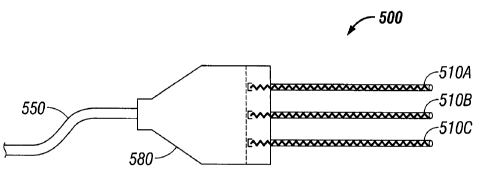
FIG. 5 shows an electrosurgical device including three helical antenna
assemblies according to another embodiment of the present disclosure. The
electrosurgical device 500 includes a first helical antenna assembly 510A, a
second helical antenna assembly 510B, a third helical antenna assembly 510C,
and a housing portion 580 coupled to a transmission line 550. Housing portion
580 may be formed of any suitable material, such as metal or plastic or
combination thereof. The shape and size of the housing portion 580 may be
varied from the configuration depicted in FIG. 5.
Although first, second and third helical antenna assemblies 510A, 510B
and 510C, respectively, extend longitudinally from the distal end of the
housing
portion 580 and are arranged substantially equally spaced apart and
substantially
parallel to each other, the number, shape, size and relative spacing of the
helical
antenna assemblies may be varied from the configuration depicted in FIG. 5.
For
example, an electrosurgical device may include six helical antenna assemblies,
arranged in a two-by-three matrix, or other suitable pattern, to substantially
simultaneously ablate a larger target volume of tissue. It is contemplated
herein
that an electrosurgical device may utilize any number of helical antenna
assemblies (or any number of sets of one or more helical antenna assemblies),
each helical antenna assembly (or set of helical antenna assemblies) being
operable independently or substantially simultaneously with respect to any
CA 02682435 2009-10-13
number of other helical antenna assemblies (or sets of helical antenna
assemblies).
First, second and third helical antenna assemblies 510A, 510B and 510C
may be axially rigid to allow for tissue penetration. For example, first,
second
and third helical antenna assemblies 510A, 510B and 510C may be sufficiently
small in diameter to be minimally invasive of the body, which may reduce the
preparation time of the patient as might be required for more invasive
penetration
of the body. As shown in FIG. 6A, a helical antenna assembly 600 includes a
tip
665, which is advantageously configured to facilitate penetration of tissue.
The
first, second and third helical antenna assemblies 510A, 510B and 510C may
also include tip portions. The helical antenna assemblies 510A, 510B and 510C
are inserted directly into tissue, through a lumen, such as, for example, a
vein,
needle or catheter, placed into the body during surgery by a clinician, or
positioned in the body by other suitable methods. The electrosurgical device
500
may include any combination of helical antenna assemblies (e.g., 510A, 510B
and 510C) and/or monopole antenna assemblies (e.g., 1920 shown in FIG. 19).
Electrosurgical device 500 may include a power splitter (not shown),
disposed within the housing portion 580, to drive energy into each of the
first,
second and third helical antenna assemblies 510A, 510B and 510C.
Transmission line 550 is coupled to an electrosurgical generator (not shown)
for
generating an output signal. A first frequency f1 is used for axial mode
(first
wavelength Ai) and a second frequency f2 is used for normal mode (second
wavelength A2,). For example, A2 may be approximately two to three times
larger
11
CA 02682435 2015-11-20
than A1 and the circumference C of the helix may be in the range of about
0.8A1
to about 1.21\1 and such that C < 0.4A2.
Referring to the embodiment shown in FIG. 6A, the helical antenna
assembly 600 includes a helical antenna radiating section 660 and a tip
portion
665. Tip portion 665 is advantageously configured for penetrating tissue.
Although the surfaces of the tip portion 665 shown in FIG. 6A are generally
flat,
that surfaces of the tip portion 665 according to various embodiments may be
curved or may include a combination of flat, sloped or curved portions. The
shape and size of the tip portion 665 may be varied from the configuration
depicted in FIG. 6A. The helical antenna radiating section 660 includes a
helical
antenna element 610, a sleeve member 621 located at the periphery of the
helical antenna element 610 coaxially with the helical antenna element 610,
and
a shell 630 located at the periphery of the sleeve member 621. Helical antenna
element 610 may be formed of a shape-memory material, such as copper-zinc-
aluminum-nickel, copper-aluminum-nickel and/or nickel-titanium (NiTi) alloys,
e.g., to adjust shape of the helical antenna assembly 600 with different
temperature perfused fluid.
FIG. 6B shows the helical antenna radiating section 660, which
corresponds to the portion of the helical antenna assembly 600 in FIG. 6A
taken
along the lines II-11. In one embodiment, the sleeve member 621 is formed of a
dielectric material and may include a material that has variable dielectric
constant, or adjustable dielectric constant, so that effective wavelengths
will vary
between the axial mode and the normal mode of operation. In one embodiment,
12
CA 02682435 2009-10-13
the helical antenna radiating section 660 includes a second dielectric
material
880 (see FIG. 8) disposed to the interior of the helical antenna element,
wherein
the sleeve member 621 and the second dielectric material 880 have
substantially
similar dielectric properties. Sleeve member 621 may be formed of an
inflatable
element, a shape-memory alloy element, magneto-electrical actuated elements,
or other activateable elements to expand the helical antenna radiating section
to
varied dimensions. Shell 630 encircles the sleeve member 621 and may be
formed of a conductive material to improve directionality and to reduce stray
electromagnetic radiation emissions. In one embodiment, the shell (1320 shown
in FIGS. 13A and 13B) is adapted to be slideably moveable along the periphery
of the sleeve member (1360 shown in FIGS. 13A and 13B).
Referring to FIG. 6B, the helical antenna radiating section 660 includes a
distal end 664. Helical antenna assembly 600 can be operated in the axial mode
to perform a procedure on a first portion of a target volume of tissue,
wherein the
first portion of the tissue is located distal to end 664 of the helical
antenna
assembly 600. Helical antenna assembly 600 can be operated in the normal
mode to perform a second procedure on a second portion of the target volume of
tissue, wherein the second portion is located substantially adjacent to the
helical
antenna radiating section 660. It is to be understood that various sequences
of
axial and normal modes of operation may be utilized depending on the
particular
application of the helical antenna assembly 600.
FIG. 7 is a cross-sectional view of the helical antenna assembly of
FIG. 6B. FIG. 7 shows the helical antenna assembly 600 including the helical
13
CA 02682435 2009-10-13
antenna element 610 enclosed by a first dielectric material 621, and the shell
630
which surrounds the length of the first dielectric material 621. First
dielectric
material 621 may include ferroelectric dielectric materials, which through
applied
DC voltage may allow control of the depth and spread of the power deposition
pattern. Shell 630 may be formed of an electrically conductive material, e.g.,
metal, and may be used as the charge accumulation conductor generating the
DC field, with the helix being the opposite electrode. Located to the interior
of
the helical antenna element 610 is a cavity 680. As described hereinbelow,
interior cavity 680 may include a dielectric material disposed therein.
FIG. 8 is a cross-sectional view of the helical antenna assembly of FIG. 6B
shown with a dielectric material disposed to the interior of the helical
antenna
element, according to an embodiment of the present disclosure. The antenna
assembly 800 of FIG. 8 is similar to the helical antenna assembly 600 shown in
FIG. 7, except that the helical antenna assembly 800 includes a second
dielectric
material 880 disposed to the interior of the helical antenna element 610,
i.e.,
instead of the interior cavity 680. In one embodiment of helical antenna
assembly 800, the first dielectric material 621 and the second dielectric
material
880 have substantially similar dielectric properties. In other embodiments,
the
dielectric properties may be substantially higher or lower in Cr', Cr" Second
dielectric material 880 may include ferroelectric dielectric materials.
Enclosing
the helical antenna element 610 and the dielectric load, e.g., first and
second
dielectric materials 621 and 880, with conductive shell 630 may aid
directionality
of the helical antenna assembly 800. Shell 630 may be longitudinally divided
into
14
CA 02682435 2009-10-13
a plurality of electrodes with a dielectric material disposed between the
electrodes, for beam steering, e.g., through ferroelectric manipulation.
FIGS. 9A and 9B show a helical antenna assembly according to another
embodiment of the present disclosure, wherein the helical antenna assembly 900
includes a helical antenna element 910, a fluid 922, an outer shell 930, and a
tip
965. Tip 965 is advantageously configured to facilitate penetration of tissue.
Helical antenna assembly 900 also includes an inner shell, located at the
periphery of the helical antenna element 910 and surrounding the length of the
helical antenna element 910, and two longitudinally formed partitions, which
form
a first channel 915 and a second channel 925 in the space between the outer
shell 930 and the periphery of the helical antenna element 910. Each of the
first
and second channels 915, 925 are utilized to hold the fluid 922. In one
embodiment, each of the longitudinally formed partitions include a number of
openings formed therein for placing the first and second channels 915, 925 in
fluid communication. In the embodiment illustrated in FIG. 9B, the first and
second channels 915 and 925 have substantially equal dimensions. Although
two channels are shown in FIG. 9B, the helical antenna assembly 900 may
include a single channel or multiple channels.
FIG. 10 shows a helical antenna assembly according to yet another
embodiment of the present disclosure, wherein the helical antenna assembly
1000 includes a helical antenna element 1010 and an outer shell 1030. The
helical antenna assembly 1000 also includes a first channel 1015 and a second
channel 1025, which are similar to the first and second channels 915, 925
shown
CA 02682435 2015-11-20
in FIG. 9B, except that the distal end portions of the first and second
channels
1015, 1025 are adapted to allow fluid circulation in opposing directions, as
indicated by the right and left arrows. Fluids having different dielectric
constants
are circulated around the helical antenna radiating section, and the effective
wavelength changes depending on the fluid dielectric properties. The
relationship between the circumference C of the helical antenna element 1010
and the effective wavelength A can be expressed by the equation I = C / (f x
sqrt(e)), where frequency f = 1/A. For example, in cases when the dielectric
constant el of a first fluid is in the range of about three to nine times the
dielectric
constant E2 of a second fluid, 0.81k1 < C < 1.2A1 and C < 0.41µ2. In one
embodiment wherein fluids are circulated around the helical antenna radiating
section, and wherein helical antenna element 1010 is formed of a shape memory
alloy, the fluid temperature is varied to change the shape of the helical
antenna
assembly 1100, for example, to assist with altering normal versus endfire
mode.
FIGS. 11A and 11B show a helical antenna assembly 1100 that includes a
housing 1165, a helical antenna element disposed with the housing 1165 and
backed by a conducting ground plane 1120, and a connector 1150 which is
coupled to the helical antenna element. Helical antenna assembly 1100 is
shown operating in an axial mode, whereby the transmission pattern 1143
extends outwardly from the distal end of the helical antenna assembly 1100.
Referring to FIG. 11B, the helical antenna assembly 1100 also includes a
dielectric element 1180 and a cavity 1170 defined between the outer shell of
the
housing 1165 and the periphery of the dielectric element 1180. Cavity 1170
16
CA 02682435 2009-10-13
includes channels for holding a fluid, e.g., first and second channels 915 and
925
for holding fluid 922 as shown in FIG. 96.
FIG. 12 is a flowchart illustrating a method for directing energy to a target
volume of tissue, according to an embodiment of the present disclosure. In
step
1210, a helical antenna assembly, e.g., 400, is positioned for the delivery of
energy to the target volume of tissue. The helical antenna assembly 400 may be
inserted directly into tissue (e.g., as shown in FIG. 4), inserted through a
lumen,
e.g., a vein, needle or catheter, placed into the body during surgery by a
clinician,
or positioned in the body by other suitable methods.
In step 1220, the helical antenna assembly is operated in a first mode
(e.g., a normal mode) of operation to perform a first procedure on a first
portion
of the target volume of tissue, the first portion being located substantially
adjacent to a longitudinal portion of the helical antenna assembly.
In step 1230, the helical antenna assembly is operated in a second mode
(e.g., an axial mode) of operation to perform a second procedure on a second
portion of the target volume of tissue, the second portion being located
distal to
an end portion of the helical antenna assembly.
FIGS. 13A and 13B show a helical antenna assembly 1300 including a
moveable shell 1320 located at a periphery of a sleeve member 1360 coaxially
disposed with respect to sleeve member 1360. Shell 1320 is adapted to be
slideably moveable along the periphery of the sleeve member 1360 between a
first position, in which an outer diametrical wall of the sleeve member 1360
is
entirely covered by the shell 1320 (see FIG. 13A), and a second position, in
17
CA 02682435 2009-10-13
which at least a portion of the outer diametrical wall of the sleeve member
1360
is exposed (see FIG. 13B). In one embodiment, when the helical antenna
assembly 1300 is operated in the normal mode, the shell 1320 is positioned in
the second position. In another embodiment, when the helical antenna assembly
1300 is operated in the axial mode, the shell 1320 may be positioned in either
the
first or second position. Shell 1320 shown in FIGS. 13A and 13B is a
substantially cylindrically-shaped structure having an inner diameter "DI",
which is
larger than an outer diameter "Do" of the sleeve member 1360. Shell 1320 may
be slideably movable to various positions such that any portion of the helical
radiating section of the helical antenna assembly 1300 may be exposed for
radiating the tissue "T".
FIG. 14 illustrates a helical antenna assembly 1400 that includes a helical
antenna element 1440 disposed with a housing 1430 and backed by a
conducting ground plane 1450 and a connector 1420, which is electrically
coupled to the helical antenna element 1440 and a transmission line 1410.
Helical antenna element 1440 may be configured as a dielectrically-loaded
endfire helical antenna, which may be suitable for microwave ablation and/or
for
use to pre-coagulate tissue for microwave ablation assisted surgical
resection.
Helical antenna assembly 1400 may have an endfire radiation pattern similar to
the endfire radiation pattern 310 of helical antenna assembly 200 shown in
FIG. 3.
In one embodiment of helical antenna assembly 1400, a substantially
cylindrically-shaped dielectric material is disposed within the housing 1430.
The
18
CA 02682435 2009-10-13
dielectric material within the housing 1430 may have a high permittivity such
that
the wavelength of the electromagnetic radiation, e.g., microwave radiation,
transmitted by the helical antenna assembly 1400 is short enough to allow for
a
compact design. Helical antenna assembly 1400 may be configured in a variety
of shapes and sizes depending on a particular surgical purpose or to
accommodate a particular surgical need.
In one embodiment of helical antenna assembly 1400, the helical antenna
element 1440 is formed of a shape-memory alloy, and the temperature of a fluid
circulated around the helical antenna radiating section is varied to expand
the
circumference of the helical antenna radiating section and/or reduce the
circumference of the helical antenna radiating section.
During various non-invasive procedures, the distal end of the helical
antenna assembly 1400 may be placed in contact with the surface of a target
tissue "T". In this instance, the endfire power would allow for targeting of
surface
tissue "T" placed in contact with the helical antenna assembly 1400. Layers of
various metals and/or dielectric around the substantially cylindrically-shaped
dielectric material disposed within the housing 1430 may be utilized to
improve
power delivery and directionality into surface tissue "T" and/or provide for a
sterilizable device. A dielectric material, e.g., a dielectric gel, may be
used
between the distal end of the helical antenna assembly 1400 and the tissue
"T",
e.g., to improve coupling.
FIG. 15 is a schematic diagram of a monopole antenna assembly 1500
that includes a monopole radiating section 1550 including a monopole antenna
19
CA 02682435 2009-10-13
element 1510 surrounded by a dielectric material 1520 and backed by a ground
plane 1530, a tip 1505, and a connector 1545, which is electrically coupled to
the
monopole antenna element 1510 and a transmission line 1540. Ground plane
1530 is configured to direct the electromagnetic radiation, e.g., microwave
radiation, into the targeted tissue and may provide a boundary to define the
resonant frequency of the monopole antenna assembly 1500.
In one
embodiment, dielectric material 1520 reduces the operating wavelength of the
monopole radiating section 1550 and may buffer the microwave wavelength from
tissue electrical property dynamics. FIG. 16 shows the transmission pattern of
the monopole antenna assembly 1500.
FIG. 17 shows the monopole antenna assembly 1500 of FIGS. 15 and 16,
positioned in the target surgical site, following the operation of the
monopole
antenna assembly 1500. FIG. 17 schematically illustrates thermal effects of
microwave energy radiated into tissue "T", whereby a portion 1770 of the
tissue
"T" is abated around the monopole antenna assembly 1500.
FIGS. 18A and 18B illustrate electrosurgical devices including multiple
monopole antenna assemblies 1820. Components of the monopole antenna
assemblies 1820 of FIGS. 18A and 18B may be similar to components of the
monopole antenna assembly 1500 shown in FIGS. 15-17 (e.g., a monopole
radiating section 1550 including the monopole antenna element 1510, dielectric
material 1520, and tip 1505), and further description thereof is omitted in
the
interests of brevity. Various numbers and configurations of monopole antenna
assemblies 1820 may utilize the same ground plane. For example, an
CA 02682435 2009-10-13
electrosurgical device 1801 shown in FIG. 18A includes a substantially
cylindrically-shaped housing 1810 configured with ten monopole antenna
assemblies 1820 that are arranged substantially parallel to each other and
which
longitudinally extend from the distal end of the housing 1810. Referring to
FIG.
18B, the electrosurgical device 1802 includes a substantially rectangular-
shaped
housing 1830 configured with sixteen monopole antenna assemblies 1820 that
are arranged substantially parallel to each other in a longitudinally
extending
manner from the distal end of the housing 1830 and aligned in a pattern of
rows
and columns.
FIG. 19 shows an electrosurgical device 1900 that includes six monopole
antenna assemblies 1920 that are commonly backed by a ground plane 1950.
Each monopole antenna assembly 1920 includes a monopole antenna element
1930 surrounded by a dielectric material 1940. Ground plane 1950 is configured
to direct the electromagnetic radiation, e.g., microwave radiation, into the
target
surgical site and may provide a boundary to define the resonant frequency of
the
respective monopole antenna assemblies 1920. The monopole antenna
assemblies 1920 are inserted directly into tissue, through a lumen, such as,
for
example, a vein, needle or catheter, placed into the body during surgery by a
clinician, or positioned in the body by other suitable methods.
Electrosurgical device 1900 also includes a power splitter 1950 that drives
energy into each of the monopole antenna assemblies 1920, which is
electrically
coupled to each of the respective monopole antenna elements 1930. In one
embodiment, power splitter 1950 is a microwave power splitter 1950.
21
CA 02682435 2009-10-13
Microwave power splitter 1950 may be implemented by any suitable
power divider that provides substantially equal power split at all output
ports.
Microwave power splitter 1950 may be implemented by any suitable power
divider that provides equal power split at all output ports while
substantially
maintaining phase and amplitude balance. For example, in one instance, the
microwave power splitter 1950 implements using a 6-way power divider that
provides equal power split at all output ports while maintaining a phase
balance
of <+/-10 degrees and amplitude balance of <1.5 dB.
Electrosurgical device 1900 also includes a connector 1965, which is
electrically coupled to the power splitter 1950 and a transmission line 1960.
Transmission line 1960 includes proximal and distal ends and may be suitable
for
transmission of microwave energy. The proximal end of the transmission line
1960 may be coupled to a microwave energy source (not shown), and the distal
end thereof is in communication with the connector 1965 of the monopole
antenna assembly 1900.
Although embodiments have been described in detail with reference to the
accompanying drawings for the purpose of illustration and description, it is
to be
understood that the inventive processes and apparatus are not to be construed
as limited thereby. It will be apparent to those of ordinary skill in the art
that
various modifications to the foregoing embodiments may be made without
departing from the scope of the disclosure.
22