Note: Descriptions are shown in the official language in which they were submitted.
CA 02682495 2009-09-30
WO 2007/112484
PCT/AU2007/000406
1
CONVEYOR IDLER ASSEMBLY
Technical Field
This invention relates to a conveyor idler assembly and in particular to a
conveyor
idler assembly for use with belt conveyors typically but not exclusively used
for conveying
particulate materials in the mining industry.
Background Art
Belt conveyors are commonly used in the mining industry for conveying
particulate
material such as mined materials for example coal or ore. Conveyors of this
type include a
moving belt for carrying the material to be conveyed supported on a plurality
of sets of
conveyor idler rollers. The conveyor idler roller sets usually include two or
more idler
rollers arranged in an end-to-end relationship. In one particular arrangement,
the conveyor
idler roller sets include a central roller and side rollers on opposite sides
of the central roller.
The conveyor idler sets further include a support frame provided with spaced
notched
brackets or lugs to receive the opposite ends of axles of the idler rollers.
The brackets may
be configured to support the rollers at an obtuse angle relative to each other
or where there
is a central roller and opposite side rollers, the side rollers at an obtuse
angle to the central
roller so that the belt supported on the rollers forms a concave dish-shape in
cross section.
Some conveyor idler sets have provision to vary the angle between the
respective rollers by
providing a plurality of mounting points for the roller axles. The rollers
thus may be
adjusted between one position in which they are axially aligned and in which
the belt
supported thereon is substantially planar to other positions where the rollers
are inclined
such that a belt supported thereon has the concave dish- or trough-like
configuration.
Removal of an idler from the conveyor idler roller sets of the above described
type
for replacement or service presents a number of difficulties. In many cases,
it is necessary
to stop the operation of the conveyor so that access can be had to the
conveyor idler sets.
Furthermore, idler replacement on idler sets at elevated locations usually
requires a
workman to wear a safety harness and may require more than one person to work
on the
idler set during this procedure. Furthermore, on ground mounted structures, a
workman is
required to lie under the return line of the conveyor belting which is not
desirable from the
point of health and safety requirements or legislation. A workman may also be
required to
lie inside the conveyor structure to replace the central idler rollers which
can also be unsafe.
Summary of the Invention
The present invention aims to provide an improved conveyor idler assembly
which
CA 02682495 2009-09-30
PCT/AU2007/000406
Received 30 January 2008
overcomes or alleviates the above disadvantages or which at least provides an
effective
alternative to the known conveyor idler assemblies. The present invention in a
further
aspect aims to provide a conveyor assembly having a series of conveyor idler
assemblies.
The present invention in yet a further aspect provides a support frame for
idler roller
cassettes of a conveyor idler assembly. Other objects and advantages of the
invention will
become apparent from the following description.
The present invention thus provides in one preferred aspect a conveyor idler
assembly for supporting a conveyor belt comprising a support frame, said
support frame
including at least one elongated longitudinally curved support beam, and a
plurality of
idler cassettes, each said idler cassette including a cradle and an idler
roller rotatably
supported on said cradle, said cradle being mounted to said support beam for
slidable
movement therealong, and wherein the curvature of said support beam determines
the
orientation of the said rollers of respective idler cassettes relative to each
other and thereby
the cross sectional profile of a said conveyor belt supported by said
rollers..
When the cradle-is mounted to the support beam, the roller supported on the
cradle
extends longitudinally relative to the support beam.
Preferably the cradle is captured to the support beam and is adapted to be
installed
endwise onto, or removed endwise from, an end of said support beam. The cradle
suitably
includes longitudinally spaced beam engagement means preferably at opposite
ends of the
cradle which capture the cradle and thus the cassette to the beam and permit
longitudinal
sliding movement of the cradle relative to the beam. The cradle when captured
to a curved
beam extends in a chordal direction relative to the beam between the opposite
end beam
engagement means. In one arrangement each beam engagement means includes a re-
entrant recess for receiving and capturing the beam. Each beam engagement
means may
comprise a C-shaped bracket which defines the re-entrant recess and which has
inwardly
oppositely directed fingers which can locate on the underside of the beam.
= The cradle may comprise a main elongated support member and end mounts
for
receiving opposite ends of a shaft or spindle of the idler roller. Retainers
may be provided
to retain the shaft or spindle to the end mounts. The main elongated support
member
suitably comprises a member of V-shaped cross section such as an angle member
with the
apex of the V uppermost and located adjacent the roller. The V-shaped member
has
opposite side flanges to act as deflectors for materials spilling from a
conveyor belt.
The main support members of adjacent cassettes may have their adjacent ends or
Amended Sheet
IPEA/AU
CA 02682495 2009-09-30
PCT/AU2007/000406
Received 30 January 2008
3
beam engagement brackets thereof in substantial abutment when supported on the
beam to
prevent ingress of debris and build-up of material between adjacent cassettes.
The ends or
brackets of the main support member may be angled to enable abutment
therebetween.
The beam may. comprise a thin elongated rail whose width is substantially
greater
than its thickness so that it is of strip-like form and elongated stiffening
means are provided
for stiffening the rail. The elongated stiffening means may comprise a rib on
the upper or
lower side of the rail. The rib may be arranged centrally of the rail and
extend at right
angles thereto so that the support beam is of a T-shaped or inverted T-shapexl
configuration_ The beam may be constructed of steel and may be curved or
alternatively
may be linear.
= In another arrangement, the least one support beam comprises a pair of
spaced
parallel rails. The cradle in this arrangement suitably includes end cradle
members adapted
to cooperate with the rails for slidable movement therealong with rollers
supported at
opposite ends to the end cradle members respectively and being adapted to be
located
between the rails. Suitably a shaft or spindle of the roller is supported at
opposite ends to
the end cradle members respectively. The end cradle members may have means
such as
slots on opposite sides adapted to cooperate with the spaced rails
respectively to capture
the cradle to the rails for slidable movement therealong.
Preferably the cradle has a central longitudinal axis and the roller is offset
front the
central axis. The roller may be offset to one side of the support beam.
Respective
cassettes may be adapted to be mounted on the support beam such that a roller
of one
cassette is offset from, or aligned with, a roller of a further cassette
supported on the beam.
Cassettes for this purpose may be simply reversed in orientation before
placement on the
support beam.
The cassettes suitably includes latching means adapted to releasably
interconnect
the cradle of one cassette to the cradle of an adjacent r-as-sette whereby a
plurality of
interconnected cassettes on the support beam can be moved together along the
support
beam which facilitates disengagement of the rassettes from one end of the
support beam_
The latching means may comprise a latching hook or lug. The latching means may
connect or disconnect adjacent cassettes by twisting or lifting one cassette
relative to the
adjacent cassette during installation of or removal of cassettes from the
support beam.
Preferably a plurality of idler cassettes are mounted to the support beam, and
the
longitudinal profile or curvature of the elongated support beam determines the
orientation
= =
Amended Sheet
IPEA/AU
CA 02682495 2009-09-30
PCT/AU2007/000406
.
Received 30 January 2008
4
of the idler cassettes and idler rollers of the cassettes relative to each
other. Suitably the at
least one support beam is symmetrically curved about a centre of curvature
arranged
centrally above the idler assembly and thus centrally of a conveyor belt
supported on the
idler assembly. The support beam is thus concave on its upper side such that
idler rollers
of the idler cassettes are arranged at an obtuse angle to each other to form a
conveyor belt
supported on the rollers into a symmetrical trough-like configuration_
Typically the support beam may support three idler cassettes comprising a
central
idler cassette and opposite side idler cassettes. The support beam is suitably
curved or of
arcuate form such that the central idler cassette and idler rollers thereof
are substantially
horizontal and the side idler cassettes and idler rollers thereof are inclined
upwardly on
opposite sides of the central idler cassette and idler rollers thereof. Thus a
conveyor belt
supported thereon will have its central portion supported on the central idler
roller
substantially horizontally and its opposite side portions angled upwardly to
define a trough
for carrying particulate material such as coal or rock.
. 15 The
support beam however may support only two idler cassettes or more than three
cassettes. When the support beam supports two idler cassettes, the idler
rollers of the idler
cassettes may be at an obtuse angle so as to define a V-shaped support for a
conveyor belt
to define thereby a V-shaped trough in the conveyor belt.
The support frame suitably includes opposite end mounting means for suspending
the support beam beneath a conveyor frame structure. Pivot means may be
assodiated with
at least one end mounting means for pivotally mounting at least one end of the
support
beam. The opposite end mounting means are suitably releasable to permit the
support
beam to pivot about the pivot axis of the pivot means between an operative
position in
which the idler cassettes support a conveyor belt and an. inoperative position
in which the
support beam is moved away from the conveyor belt and in which cassettes may
be moved
endwise from or endwise onto the support beam from one end of the support beam
such as
from a conveyor walkway on one said of a conveyor.
Most preferably each mounting means includes pivot means, one or other of the
pivot means being releasable to permit the support beam to pivot about either
end away
from the operative position.
The mounting means suitably comprise end mounting brackets at opposite ends of
the support beam and the pivot means suitably pivotally connect each mounting
bracket to
a hanger bracket which may be mounted to the conveyor frame structure. The
pivot
Amended Sheet
IPEA/AU
PCT/AU2007/000406
CA 02682495 2009-09-30
Received 30 January 2008
connection between the mounting bracket and hanger bracket suitably defines a
pivot axis
extending longitudinally relative to the conveyor belt. Preferably the pivot
connection is
defined by a releasable pivot pins.
Suitably means are provided for limiting the pivotal movement of the support
beam
5 beyond the inoperative position. Such means may comprise a flexible
element or chain
fixed to and extending between an end mounting bracket and associated hanger
bracket.
Whilst the support beam in this aspect is typically curved as described, it
may also
be linear with the rollers of the respective cassettes supported thereon being
substantially
coplanar to support a substantially flat or planar conveyor belt.
In anothcr preferred aspect, the present invention provides a support frame
for one
or more conveyor idler cassettes, each said cassette including a cradle
rotatably supporting
at least one idler roll, said support frame including an elongated support
beam, said cradle
being adapted to be mounted to said support beam for slidable movement
therealong with
said roller or rollers extending longitudinally relative to said support beam,
and wherein
said support beam is longitudinally curved to thereby determine the
orientation of a roller
of a said idler cassette on said beam.
In yet another preferred aspect, the present invention provides a conveyor
assembly
comprising a plurality of conveyor idler assemblies and a conveyor belt
supported on said
conveyoi- idler assemblies, each said idler assembly comprising a support
frame, said
support frame including at least one elongated linear or longitudinally curved
support
beam, and at least one idler cassette, said idler cassette including a cradle
and an idler roller
rotatably supporting on said cradle, said cradle being mounted to said support
beam for
slidable movement therealong and wherein the curvature of said support beam
defines the
orientation of said roller of said cassette.
Preferably the conveyor idler assembly includes a plurality of idler cassettes
and
the curvature of the support beam defines the orientation of rollers or
respective cassettes
relative to each other and the transverse profiled of the conveyor belt
supported on the
rollers.
Suitably the support frame includes mounting means for mounting opposite ends
of
the support beam to a conveyor frame strUcture such that the support beam is
suspended
from the frame structure. Suitably at least one mounting means has pivot means
for
pivotally connecting the support beam to the frame structure. The opposite end
mounting
means suitably is releasable to permit the support beam to pivot about the
pivot means
Amended Sheet
IPEAJAU
CA 02682495 2014-01-31
5a
between an operative position in which idler cassettes on said beam support
the conveyor
belt and an inoperative position in which the support beam is spaced from the
conveyor belt
and in which the cassettes may be moved endwise from or endwise onto the at
least one
support beam from one end of the support beam.
The support beam for the cassettes may be of any cross sectional configuration
for
example of a T-shaped or inverted T-shaped cross section, of a V or inverted V-
shape.
hollow round or "clover leaf' cross section or of any other shape. The support
beam may also
include one or multiple rails of the above or other configurations. The term
"support beam"
thus as used through the specification and claims includes beams or
combination of beams
as referred to above or one or more beams or rails of any other cross
sectional configuration.
The components of the conveyor idler assembly may be constructed of metal or
composite
materials.
According to an aspect of the invention, there is provided a conveyor idler
assembly
for supporting a conveyor belt, said idler assembly comprising a support
frame, said support
frame including at least one elongated longitudinally curved support beam, and
a plurality of
idler cassettes, each said idler cassette including a cradle and an idler
roller rotatably
supported on said cradle, said cradle being mounted to said support beam for
slidable
movement therealong, and wherein the curvature of said support beam determines
the
orientation of said rollers of respective idler cassettes relative to each
other and thereby the
cross sectional profile of said conveyor belt supported by said rollers.
According to a further aspect of the invention, there is provided a support
frame for
one or more conveyor idler cassettes, each said cassette including a cradle
rotatably
supporting at least one idler roll, said support frame including an elongated
support beam,
said one or more cassettes being adapted to be mounted to said support beam
for slidable
movement therealong with said roller or rollers extending longitudinally
relative to said
support beam, and wherein said support beam is longitudinally curved to
thereby determine
the orientation of said roller of a said idler cassette on said support beam.
According to another aspect of the invention, there is provided a conveyor
assembly
comprising a plurality of conveyor idler assemblies and a conveyor belt
supported on said
conveyor idler assemblies, each said idler assembly comprising a support
frame, said support
frame including at least one elongated longitudinally curved support beam, and
at least one
idler cassette, said idler cassette including a cradle and an idler roller
rotatably supporting on
CA 02682495 2014-01-31
5b
said cradle, said cradle being mounted to said support beam for slidable
movement
therealong and wherein the curvature of said support beam defines the
orientation of said
roller of said cassette.
CA 02682495 2009-09-30
WO 2007/112484 PCT/AU2007/000406
6
Brief Description of the Drawings
Preferred embodiment of the invention will now be described with reference to
the
accompanying drawings in which: -
Figs. 1 illustrates in isometric view a conveyor idler assembly according to
an
embodiment of the present invention with an associated conveyor belt shown cut-
away;
Figs. 2, 3 and 4 are end, top and side views of the conveyor idler assembly of
Fig. 1;
Fig. 5 is an enlarged sectional view along line A-A of Fig. 2 showing the
idler
cassette clamp;
Fig. 6 illustrates the main support beam of the conveyor idler assembly of
Figs. 1 to
4;
Fig. 7 is an underside view of a hanger bracket for the conveyor idler
assembly;
Fig. 8 is an isometric view of the cradle of a conveyor idler cassette of the
conveyor
idler assembly;
Figs. 9 and 10 are top and side views of the cradle of Fig. 8;
Fig. 11 illustrates the conveyor idler assembly with the main support frame
lowered
for idler cassette installation or removal;
Fig. 12 illustrates the manner in which a series of idler cassettes may be
installed or
removed from the support beam;
Fig. 13 illustrates in isometric view a conveyor idler assembly of the type
illustrated
in Fig. 1 but having a linear support beam;
Fig. 14 is an isometric view of an alternative conveyor idler assembly
according to
another embodiment of the invention;
Fig. 15 is an end view of the idler assembly of Fig. 14;
Fig. 16 is an isometric view of the support frame of the conveyor idler
assembly of
Fig. 14;
Fig. 17 is an isometric view of a roller cradle of a cassette for use with the
idler
assembly of Fig. 14;
Fig. 18 is an end view of the roller cradle of the cassette of Fig. 17;
Fig. 19 is an isometric view of a pair of conveyor idler assemblies according
to
another embodiment of the invention; and
Fig. 20 is an exploded view of one idler assembly of Fig. 19.
Detailed Description of the Preferred Embodiment
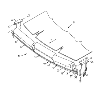
Referring to the drawings and firstly to Figs. 1 to 4, there is illustrated a
conveyor
CA 02682495 2009-09-30
WO 2007/112484 PCT/AU2007/000406
7
idler assembly 10 in accordance with an embodiment of the invention for
supporting a
conveyor belt 11 (shown cut-away), the idler assembly 10 including a support
frame 12 and
three conveyor idler roller cassettes comprising a central idler cassette 13
and opposite end
idler cassettes 14 and 15 which are described further below. The support frame
12 as
shown also in Fig. 6 includes a main elongated support member or beam 16 which
comprises a thin-strip like element and which defines a track or rail for
engagement by the
idler roller cassettes 13, 14 and 15. The beam 16 is of a symmetrical concave
curved or
arcuate configuration having a radius R on a centre spaced above and
positioned centrally
intermediate opposite sides of the assembly 10 and belt 11 and aligned with
the central
longitudinal axis of the belt 11 (see Fig. 4). The beam 16 is supported on its
underside by a
correspondingly curved rib or strongback 17 which extends the full length of
the member
16 and which is secured to the member 16 to provided support to the member 16
along its
length. In cross section, the member 16 and support rib 17 are of a T-shaped
configuration.
The member 16 and rib 17 are typically formed of steel and interconnected by
welding.
The support frame 12 additionally includes end mounting brackets 18 of J-
shaped
configuration and formed of metal plate. The brackets 18 have a lower
connection part 19
connected to the underside of the beam 16 and to the rib 17 and an outwardly
stepped leg
which is offset from the end of the member 16, the leg 20 terminating at its
upper end in
a tubular pivot mount 21. The pivot mounts 21 enable the support frame 12 to
be mounted
20 to spaced hanger brackets 22 which are mounted to a conveyor frame
structure (shown in
dotted outline in Fig. 4) such that the support beam 16 extends substantially
at right angles
to the belt 11 and is suspended beneath the conveyor frame structure by the
end mounting
brackets 18.
The hanger brackets 22 are of angle bracket form and provided with spaced
tubular
hanger members 23 (see Fig. 7) spaced apart such that the a tubular pivot
mount 21 can be
received therebetween. When the tubular pivot mount 21 is aligned with the
hanger
mem/hers 23 of a bracket 22, a detachable pivot pin 24 can be inserted through
the members
23 and mount 21 to define a pivot axis X-X which is substantially at right
angles to the
beam or member 16. Similar pivot connections are provided in this embodiment
at each
end of the support frame 12 and allow one or the other of the mounting
brackets 18 to be
disconnected from its associated hanger bracket 22 and permit the support beam
16 and
conveyor idler cassettes 13, 14 and 15 mounted thereon to be pivoted
downwardly about a
hinge axis X -X at one or the other end of the support frame 12 which
facilitates service to
CA 02682495 2009-09-30
WO 2007/112484
PCT/AU2007/000406
8
the conveyor idler assembly or replacement, changing or repair of idler roller
cassettes 13,
14 and 15 from one side of the support frame 12 as described further below.
The idler roller cassettes 13, 14 and 15 are of substantially identical
configuration
and thus only the cassette 13 will be described. As shown in Figs. 8 to 10,
the cassette 13
has a cradle comprising a main elongated mounting member 25 which is of a V-
shaped
cross section and typically comprising angle iron with the apex 26 of the
member 25 being
uppermost with the opposite flanges 24 of the member 21 being inclined
outwardly from
the apex 26 on opposite sides. A pair of end roller mounting brackets 27 are
secured to the
member 25 adjacent opposite ends thereof to extend upwardly from the apex 26
of the
member 25. The end mounting brackets 27 have slots 28 in which respective
opposite ends
of a roller shaft or spindle 29 which supports an idler roller 30 can be
received. Spring-
loaded end plates or other securing airangement may be provided to secure the
shaft 29 to
each end bracket 27. It will be noted in Fig. 10 that the apex 26 of the V-
shaped mounting
member 25 is adjacent to and below the periphery of the roller 30 and extends
substantially
parallel thereto. The shaft receiving slots 28 of the mounting brackets 27
however are offset
relative to the longitudinal centreline of the member 25 to thereby offset the
shaft 29 and
roller 30 relative to the longitudinal centreline of the member 25 as is
apparent in Fig. 9.
A pair of slide brackets 31 are secured to opposite ends of the member 25 on
the
lower side of the member 25. Each bracket 31 is formed with a C-shaped re-
entrant recess
32 of a similar cross section to, and complementary to the beam or member 16
so as to be
capable of receiving the beam 16 to capture the idler roller cassette 13 to
the beam 16 but
allow sliding movement therealong. The bracket 31 include opposed inwardly
directed
fingers 33 which define the recess 32 and which are adapted to locate on the
underside of
the beam 16 at each end of the cassette 13 to retain the brackets 31 and thus
the cassette 13
to the beam 16. The brackets 31 whilst extending substantially parallel to
each other
transversely of the member 25 are angled at an obtuse angle to each other in a
vertical
longitudinally extending plane to allow for abutment between brackets 31 of
adjacent
cassettes 13 on a curved beam 16.
Each bracket 31 also carries a hook-like latching lug 34 with the lug 34 of
one
bracket 31 being on the opposite side to the lug 34 on the opposite end
bracket 41. The lug
34 on one bracket 31 can hook over the adjacent bracket 31 of an adjacent
cassette 14 (or
15) to interlock adjacent cassettes 13, 14 and 15 in an end-to-end
relationship. The lugs 34
of one cassette 13 may be disconnected from engagement with a bracket 31 of an
adjacent
CA 02682495 2009-09-30
WO 2007/112484
PCT/AU2007/000406
9
cassette 14 (or 15) and vice-versa by twisting one cassette 13 relative to the
adjacent
cassette 14 (or 15) when being removed from or being installed onto the beam
16. This
will therefore disconnect adjacent cassettes 13 and 14 (or 15). The lugs 34
however enable
all cassettes 13, 14 and 15 on the beam 16 to be interconnected and slid as
one along the
beam 16.
To hold cassettes 13, 14 and 15 in a fixed position along the beam 16, the
beam 16
is provided with slots 36 at each end through which a U-shaped end clamping
member 37
(see also Fig. 5) may project to abut against the adjacent slide bracket 31.
The clamping
member 36 is releasably held in position by means of a clamp stud 38 captured
freely to an
end of the support frame 12, the clamp stud 38 extending through an opening 39
in the
clamping member 37 and cooperating with a nut 40 which can be tightened to
clamp the
member 37 in position against a bracket 31.
A chain 41 or other flexible element is connected between the hanger bracket
22
and mounting bracket 18 to take the weight of the end of the support frame 12
and idler
cassettes 13, 14 and 15 when lowered as described below.
In the operative position of Fig. 1 to 4, three idler cassettes 13, 14 and 15
are
mounted to the beam 16 to support the conveyor belt 11. One of the cassettes
13 is
positioned centrally of the beam 16 whilst the other two cassettes 14 and 15
comprise left
and right hand side cassettes located on the opposite sides of the central
cassette 13. It will
be apparent the belt 11 supported on the rollers 30 of the respective
cassettes 13, 14 and 15
will be formed into a trough-shaped configuration in cross section due to the
upwardly
inclined orientation of the side cassettes 14 and 15 as defined by the
longitudinal curvature
in the beam 14.
Further as illustrated, the left and right hand cassettes 14 and 15 are
transversely
aligned whilst the central cassette 13 is offset rearwardly from the side
cassettes 14 and 15
relative to the direction of movement of the belt 11 indicated by the arrow Y
in Figs. 1 and
2. After the cassettes 13, 14 and 15 are positioned on the beam 16, the end
clamping
members 37 are applied to the opposite ends of the beam 16 hold the cassettes
13, 14 and
15 in end-to-end relationship with each other. In addition, the end brackets
31 of the
respective members 25 of adjacent cassettes 13, 14 and 15 substantially abut
and mate with
each other as shown in Fig. 4 so that the members 25 form a substantially
continuous
bather along the beam 16 which reduces the possibility of any material or
debris dropping
from the conveyor belt 11 passing between the cassettes 13, 14 and 15. If the
cassettes 13,
CA 02682495 2009-09-30
WO 2007/112484
PCT/AU2007/000406
14 and 15 are to be used on a beam 16 with a different curvature, the brackets
31 of the
cassette members 25 are adjusted in angle so as to enable them to abut. The
outwardly
inclined surfaces 24 of the members 25 further act as ramps or deflectors to
guide any
material dropping from the belt 11 away from and outwardly of the cassettes
13, 14 and 15.
5 Where an idler cassette 13, 14 or 15 is to be replaced or serviced, a
hand operated
chain winch 42 (known as a cumalong) is connected between the hanger bracket
22 and
mounting bracket 18 and operated to tension the chain 43 to take the weight of
the end of
the support frame 12 which allows the pivot pin 24 to be detached to release
that end of the
support frame 12. The winch 42 may then be further operated to lower the
released end of
10 the support frame 12 which pivots about the opposite pivot pin 24 until
the chain 41
becomes tensioned and takes the weight of the frame 12 as shown in Fig. 11.
This
procedure can all be carried out by a single workman on a walkway on one side
of the
conveyor and when the belt 11 is moving and thus the workman is not exposed to
danger.
Further as the mounting brackets 18 are stepped outwardly from the opposite
ends of the
cassette support beam 16, a workman in releasing a pivot pin 24 and lowering
and raising
the frame 12 and removing or replacing cassettes is not exposed to the
hazardous area
beneath the idler assembly 10.
After the support frame 12 and thus beam 16 is lowered, the clamping member 37
can be removed by undoing the clamping nut 39 and the idler cassettes 15, 13
and 14 can be
slid endwise from the lowered end of the beam 16 as illustrated in Fig. 12.
Because the
cassettes 13, 14 and 15 are releasably interconnected by the connecting lugs
34, as the
cassette 15 is slid from the beam 16, the other cassettes 13 and 14 are also
pulled along the
beam. To release the lugs 34, the leading cassette 15 is twisted slightly in
the direction Z as
it is withdrawn from the end of the beam 16 to disconnect it from the adjacent
cassette 13
and this procedure is repeated for the next cassette.
For installation, an idler cassette 13, 14 or 15 may be slid endwise onto the
beam
16 from one end thereof by positioning the respective brackets 31 of the
cassettes 13, 14
and 15 such that the beam 16 may be received in the recesses 32 of the
brackets 31. When
the beam 16 is located in the recesses 32, the cassette 13, 14 or 15 is
captured to the beam
16 but is capable of longitudinal sliding movement along the beam 16 so that
it can be
positioned where required along the beam 16. Each subsequent cassette is
slightly twisted
prior to installation to enable the respective cassettes to be interconnected
through the lugs
or hooks 34. After installation, the cassettes 14, 15 and 16 may be held in
position by the
CA 02682495 2009-09-30
WO 2007/112484
PCT/AU2007/000406
11
clamping members 37.
Whilst the cassettes 13, 14 and 15 are shown with the central cassette 13
offset from
the side cassettes 14 and 15 in Figs. 1 to 4, the orientation of the central
cassette 13 may be
reversed so that its roller offset is on the same side as the roller offsets
of the opposite end
cassettes 14 and 15. Thus all rollers 30 of the cassettes 14 and 15 will be
longitudinally
aligned as shown in dotted outline in Fig. 3. Alternatively the end cassettes
14 and 15 can
be reversed to align their rollers 30 with the roller 30 of the central
cassette 13.
The curvature of the profile of the rail-like beam 16 may be varied to suit
the
application so that the orientation of the cassettes 13, 14 and 15 supported
on the beam 16
may be varied. Thus an increase concavity in the beam 16 will result in a
deeper trough in
a belt 11 supported on the cassettes 13, 14 and 15.
The idler assembly 10' of Fig. 13 is substantially the same as the assembly 10
except that the beam 16 and rib 17 are of a linear form so that the rollers 30
of cassettes 13,
14 and 15 supported thereon are substantially coplanar but are installed and
removed in the
same manner as described above.
The conveyor idler assembly of the present invention may in most cases be
fitted to
exiting mounting points as used for conventional idler assemblies and
respective cassettes
13, 14 and 15 may be installed in a single person operation from one side of
the conveyor
belt 11. Replacement of idler cassettes 13, 14 or 15 also removes the need to
use safety
harnesses at heights and the need to lie under the return strand of the
conveyor belt to
change return idlers on ground mounted structures. In addition, there is no
need to lie
inside conveyor structures to replace cassette idlers. Further idler rollers
can be replaced
without the need to raise the belt 11 and further whilst the belt 11 is
moving. The mounts
for the conveyor idler assembly may be varied to suit the location of an
assembly within a
conveyor structure. The mounting of the idler cassettes when assembled with
its support
frame renders the cassettes and rollers thereof much less prone to damage
during
transportation.
The cassettes 13, 14 and 15 although showing the rollers 30 offset from the
central
longitudinal axis of the main support member 25, may have the rollers 30
aligned with that
axis. The members 25 of the cassettes 13, 14 and 15 may be varied in design
and different
end mounting brackets may be provided for supporting the roller shafts 29.
Whilst the
beam 16 is supported by the bracing rib 17 on its underside, to reduce overall
height, the rib
17 may be provided on the upper side of the beam 16. The brackets 30 may be
varied for
CA 02682495 2009-09-30
WO 2007/112484
PCT/AU2007/000406
12
example by being provided with slots to accommodate the rib 17 on the upper
side of the
beam 16. The rail-like beam 16 may be in other configurations than that
described and
illustrated. The brackets 31 may also be varied in configuration and replaced
for example
by angle brackets on opposite sides of the member 25. The member 25 may also
be in
configurations other than the V-shaped configuration described. The clamping
members 37
may also be in various configurations but the clamping members 37 are suitably
designed
so that the idler cassettes 13, 14 and 15 are held firmly in end-to-end
abutment with each
other when clamped at each end.
Referring now to Figs. 14 and 15, there is illustrated a conveyor idler
assembly 43
in accordance with another embodiment of the invention which is used for low
profile
applications. The assembly 43 includes a support frame 44 which carries three
idler
cassettes 45, the support frame 44 having end mounting brackets 46 at each end
by which
the frame 44 can be suspended from a conveyor frame structure via hanger
brackets 47 in a
similar manner to the previously described embodiments. The end brackets 46
are
connected to hanger brackets 47 through releasable pivot connection 48 similar
to that
previously described which allows one or other end of the frame 44 to be
released and
pivotally lowered for replacement and instalment of the idler cassettes 45.
The support
frame 44 in this case includes a pair of parallel arcuate rails 49 (see Fig.
6) which are fixed
to and extend between the end brackets 46. The rails 49 are of angle section
form in cross
section and have a symmetrical curved concave configuration in longitudinal
profile. One
flange 50 of each rail 49 is substantially horizontal and directed inwardly to
oppose the
other flange 50.
As shown in Figs. 17 and 18, each idler cassette 45 comprises a roller cradle
51
having a pair of parallel side cradle members 52 of angle section form and
pair of parallel
end cradle members 53 connected to the side cradle members 52. Slots 54 extend
inwardly
from opposite lateral sides of the cradle members 53, the slots 54 being
complementary to
the flanges 50. A pair of upstanding end roller mounting lugs 55 are secured
to the end
cradle members 53 respectively at a position offset from the longitudinal
central axis of the
cradle 51. The lugs 55 are provided with slots 56 in which respective opposite
ends of a
roller shaft or spindle 56 which supports an idler roller 57 can be received.
Any suitably
releasable securing arrangement may be provided to secure the shaft 56 to each
lug 55.
Each end cradle member 53 also carries a hook-like lug 58 with the lug 58 of
one
member 53 being on the opposite side to the lug 58 on the opposite member 53.
The lug 58
CA 02682495 2009-09-30
WO 2007/112484 PCT/AU2007/000406
13
on one member 53 can hook over the adjacent member 53 of an adjacent cassette
45 to
releasably interlock adjacent cassettes 45 in an end-to-end relationship.
For installation, an idler cassette 45 is positioned to align the slots 54
with the
respective rail flanges 50 and the cassette 45 may then be slid endwise onto
the rails 49
such that it is captured to the frame 44 but is capable of longitudinal
sliding movement.
Each subsequent cassette 45 is slightly lifted upwardly relative to the
preceding cassette 45
whose end projects outwardly of the rails 49 to enable the hook or lug 58 of
the trailing
cassette 45 to be hooked over the member 53 of the leading cassettes 45 which
interconnects the cassettes 45 and allow them to be moved as one when
installed on the
rails 49. The cradles 51 as in the preceding embodiments cannot be
disconnected from each
other when engaged with the rails 49. After installation, the cassettes 45 may
be held in
position by clamps 59 similar to the clamp 37 of Fig. 5.
Respective cassettes 45 may be positioned as shown in Fig. 14 so that the
roller 57
of the central cassette 45 is offset from the rollers 57 of the opposite side
cassettes 45
however the orientation of the central cassette 45 may be reversed so that its
roller 57 is
aligned with the rollers 57 of the other cassettes 45. Alternatively the end
cassettes 45 can
be reversed to align with the central cassette 45.
Cassettes 45 may be removed and/or replaced in the same manner as described
with
reference to Figs. 11 and 12 with one end of the support frame 44 being
lowered to allow
sliding of cassettes 45 in turn from the rails 49 from one side of the
conveyor. Cassettes 45
are installed in a reverse mariner as described above.
Figs. 19 illustrate a pair of alternative conveyor idler assemblies 60
according to the
invention which are particularly applicable to a ship loading conveyor
assembly comprising
one conveyor which can be extended from another conveyor. Each idler assembly
60 as
also shown in Fig. 20 includes six idler cassettes 61 supported slidably on an
elongated
arcuate support beam 62 which in this case is of an inverted T-shaped cross
section. Each
cassette 61 includes a cradle 64 having end cradle members 65 secured to
opposite ends of
a main frame member 66 which is of an inverted V-shaped cross section. The
cradle
members 65 are provided with re-entrant recesses 67 which are aligned with the
inverted V-
shaped member 66 and which are similar shape to the cross section of the beam
62. This
enables the cradle 64 to be slid endwise onto the beam 62 which will be
captured in the
recesses 67. The cradle members 65 extend to one side of the frame member 66
and have
mounts 68 to receive opposite ends of a spindle 69 of an idler roller 70 which
position the
CA 02682495 2009-09-30
WO 2007/112484 PCT/AU2007/000406
14
idler rollers 70 in use laterally of the beam 62. Clamping assemblies 71 are
provided at
opposite ends of the beam 62 for clamping the cassettes 61 in position when
located on the
beam 62. As with the previous embodiments, latch like-lugs or hooks 72 are
provided on
the cradle members 65 to hook over the adjacent cradle member 65 of an
adjacent cassette
61 during installation on the beam 62 to interconnect the cassettes 61 end -to
end when on
the beam 62.
Opposite ends of the beam 62 are connected to mounting brackets 73 which are
spaced outwardly of the ends of the beam 62, the mounting brackets 73 being
provided with
pivot mounts 74 for pivotally connecting the brackets 73 to hanger brackets 75
via
releasable pivot pins 76. The hanger brackets 75 are mounted to respective
frame members
77 and 78 of conveyor structures, the lower frame members 78 being mounted for
movement longitudinally relative to the upper frame members 77.
As with the previous embodiments, the pin 76 on one side of the beam 62 may be
released to allow the beam 62 carrying the cassettes 61 to be pivoted
downwardly about the
opposite pivot pin 76 to allow removal or replacement of the cassettes 61
which may be slid
endwise from or endwise onto the beam 62 after removal of the clamps 71. Of
course to
permit pivoting movement of the beam 62 of the upper idler assembly 60, it is
necessary to
move the upper and lower idler assemblies 60 out of vertical alignment with
each other by
sliding one set of frame members 78 relative to the other set 77.
As shown in the drawings, the central two cassettes 61 have their rollers 70
on one
side of the beam 62 whilst the other end cassettes 61 have their rollers on
the opposite side
of the beam 62. The central cassettes 61 however may be reversed so that all
rollers 70 are
aligned transversely of a conveyor belt supported on the rollers 70.
Whilst the embodiment of Figs. 18 and 19 shows an idler assembly 60 with six
idler
cassettes, any of the idler assemblies described above may have any number of
cassettes.
The reference to prior art in the above description is not to be taken as an
admission that the prior art constitutes common general knowledge in the art.
The terms "comprising" or "comprise" or derivatives thereof as used throughout
the
specification and claims are taken to specify the presence of the stated
features, integers and
components referred to but not preclude the presence or addition of one or
more other
feature/s, integer/s, component/s or group thereof