Note: Descriptions are shown in the official language in which they were submitted.
CA 02682644 2009-10-01
Agent Ref: 68201/00012
1 Ladder-Type Insulating Strut for a Composite Profile for Window, Door and
Facade
2 Elements and Composite Profile for Window, Door and Facade Elements
3
4 The present invention relates to a ladder-shaped insulating strip for a
composite profile
for window-, door- and facade elements and a composite profile for window-,
door- and facade
6 elements.
7
8 Insulating strips for composite profiles for window-, door- and facade
elements and
9 composite profiles for window-, door- and facade elements are known, e.g.,
from DE 296 23 019
Ul (EP 0 829 609 B1), DE 197 35 702 A1, DE 298 21 183 U1 (EP 1 004 739 B1), DE
199 56
11 415C1,DE19818769A1 andDE19853235A1.
12
13 An insulating strip is known from DE 198 18 769 Al that is comprised of
plastic and an
14 embedded metal insert. The metal insert and the plastic have openings that
result in a ladder-
shaped structure of the ladder strip. The metal insert serves to prevent a
total failure of the
16 insulating strip in case of fire. The purpose of the openings in the metal
insert is to reduce heat
17 conductivity.
18
19 It is an object of the invention to provide an insulating strip (thermal
isolating strip) for a
composite profile, which facilitates a sufficiently high shear rigidity with
improved thermal
21 isolation, and a composite profile improved in this manner.
22
23 This object is achieved by an insulating strip according to claim 1, a
covering profile
24 according to claim 4 and a composite profile according to claim 5,
respectively.
26 Further developments of the invention are provided in the dependent claims.
27
28 A composite profile, in particular a metal composite profile, is provided,
in which the
29 outwardly-located profile parts (e.g., outer frame and inner frame) made,
e.g., of metal, are
connected using one or more insulating strips made of plastic. A relative
movement in the
21925645.1 1
CA 02682644 2009-10-01
Agent Ref: 68201 /00012
1 longitudinal direction is limited and/or prevented by the high shear
rigidity (characteristic of the
2 rungs in width, thickness, length, number).
3
4 The insulating strips are advantageously manufactured initially from a
suitable material,
e.g., by extrusion, as profile parts having a constant cross-section along the
length. Thereafter,
6 the rungs and/or more precisely the openings are produced by a processing
such as a machine
7 processing (e.g., milling), cutting (e.g., laser cutting, water jet
cutting), punching, etc. The
8 removed material can be recycled.
9
The metal profiles are fixedly and thus undetachably connected with the
insulating strip.
11
12 The insulating strips can be provided with covering profiles or covering
foils for covering
13 the intermediate spaces between the rungs. The covering profiles or
covering films can be, e.g.,
14 clipped-on, adhered-on, extruded-on, laminated-on, etc. In the alternative
or in addition, it is
also possible to fill up the intermediate spaces between the ladder rungs with
a material that has a
16 lower heat conductivity coefficient than the material of the rungs. The
function of such a
17 covering profile, etc., is, on the one hand, to protect against the
penetration of moisture and, on
18 the other hand, the protection of the inner core. The covering profiles or
covering films can be
19 attached before or after the mounting of the doors. The protection against
moisture can be
ensured with the covering profiles or covering films. In addition, decorative
elements can be
21 attached. For example, the covering element can be made electronically
conductive and thus
22 assume the color of the metal profile during the powder lacquering.
Printing thereon is also
23 possible.
24
One advantage is that the U-values (heat conductivity properties) of the
insulating strip
26 are not inordinately diminished by the attachment of the covering
film/covering profile/filling.
27
28 Further features and advantages will follow from the description of the
exemplary
29 embodiments with the assistance of the Figures. In the Figures:
21925645.1 2
CA 02682644 2009-10-01
Agent Ref: 68201/00012
1 Fig. 1 shows a first embodiment of an insulating strip, in a) in plan view,
in b) in the
2 cross-section perpendicular to the longitudinal direction along the line B-B
from Fig. 1 a), and in
3 c) in the cross-section perpendicular to the longitudinal direction along
the line C-C from Fig.
4 l a);
6 Fig. 2 shows a second embodiment of an insulating strip having another rung
width in
7 views corresponding to Fig. 1;
8
9 Fig. 3 shows a cross-sectional view perpendicular to the longitudinal
direction of an
insulating strip when being connected with the inner- and outer profile parts
of a composite
11 profile by rolling-in;
12
13 Fig. 4 shows a third embodiment of an insulating strip having meander-
shaped rungs of
14 the ladder-like structure in a view corresponding to Fig. 1 a);
16 Fig. 5 shows a fourth embodiment of an insulating strip having an in situ
extruded cover
17 in a view corresponding to Fig. 1 c);
18
19 Fig. 6 shows a modification of the fourth embodiment;
21 Fig. 7 shows a fifth embodiment of an insulating strip, in a) in the cross-
section of the
22 insulating strip body perpendicular to the longitudinal direction, in b) in
the cross-section of a to-
23 be-clipped-on covering profile perpendicular to the longitudinal direction,
and in c) in the
24 installed state between two metal profiles in the cross-section
perpendicular to the longitudinal
direction; and
26
27 Fig. 8 shows in the views a), b) a sixth embodiment of an insulating strip,
in a) in plan
28 view perpendicular to the longitudinal direction and in b) in the cross-
section perpendicular to
29 the longitudinal direction, in view c) a modification of the sixth
embodiment in the cross-section
perpendicular to the longitudinal direction, in d) a seventh embodiment in
plan view
31 perpendicular to the longitudinal direction, in e) an eighth embodiment in
plan view
21925645.1 3
CA 02682644 2009-10-01
Agent Ref: 68201/00012
1 perpendicular to the longitudinal direction, and in f) a ninth embodiment in
plan view
2 perpendicular to the longitudinal direction;
3
4 Fig. 9 shows a tenth embodiment of an insulating strip, in a) in plan view
perpendicular
to the longitudinal direction and in b) in the cross-section perpendicular to
the longitudinal
6 direction;
7
8 Fig. 10 shows an eleventh embodiment of an insulating strip, in a) in plan
view
9 perpendicular to the longitudinal direction, in b) in the cross-section
perpendicular to the
longitudinal direction, in c) in a modification of the cross-sectional shape
perpendicular to the
11 longitudinal direction, in d) a cross-section without openings, in e) a
modification of the
12 embodiment of b) with filling material, and in f) a modification of the
modification of c) with
13 filling material;
14
Fig. 11 shows modifications of the sixth to ninth embodiments in corresponding
views;
16 and
17
18 Fig. 12 shows in a) a modification of the embodiments from Figs. 10 a) and
c), in b) and
19 c) modifications of the embodiments of Figs. 8 and 11, and in d) a
modification of the
embodiment of Fig. 10.
21
22 In the insulating strips shown in Figs. 1, 2, the rungs 23 of the
insulating strip body 20,
23 which is formed in a ladder-like manner, extend transverse to the
longitudinal direction Z
24 between the continuous longitudinal edges 21, 22. However, these could also
extend slightly
inclined (up to about 20 ) to the transverse direction. The rungs could also
have a curved shape.
26 All rungs preferably, but not necessarily, have the same shape.
27
28 The longitudinal sides or edges 21, 22 are adapted for the (in the
longitudinal direction Z)
29 shear-resistant connection with profile parts 31, 32 (see Fig. 3) of the
composite profile. In the
illustrated embodiment, the longitudinal sides or edges 21, 22 are formed as
roll-in heads 25 or
31 roll-in projections for a rolling-in in grooves of the profile parts 31,
32, which are each formed
21925645.1 4
CA 02682644 2009-10-01
Agent Ref: 68201/00012
1 by a roll-in hammer 33 and an opposing wall segment 34. Other types of
connections, such as
2 adhesion, etc. are also possible.
3
4 In plan view, the rungs 23 have a width b in the longitudinal direction z
that is chosen in
accordance with the required transverse tensile strength, the required
transverse stiffness and the
6 material utilized and falls within the range of 0.5 mm to 10 mm, preferably
1 mm to 5 mm, more
7 preferably 1 mm to 3 mm. In a cross section perpendicular to the
longitudinal direction, the
8 rungs have a height (thickness) h (in direction y) that is chosen in
accordance with the required
9 transverse tensile strength, the required transverse stiffness and the
material utilized and falls
within the range of 0.5 mm to 10 mm, preferably 0.5 mm to 5 mm, more
preferably 0.7 mm to 2
11 mm. The rungs 23 are disposed in the longitudinal direction with constant
spacings d between
12 them, which spacings fall within the range of 1 mm to 100 mm, preferably 1
mm to 50 mm, more
13 preferably 1 mm to 5 mm and more preferably 1 to 3 mm. Naturally, other
widths, thicknesses,
14 lengths and spacings are possible in accordance with the requirements.
16 First test results were obtained from ladder-like insulating strips with
rungs that had, in
17 the plan view in the longitudinal direction of the insulating strip, a
width b of 1 mm in a first
18 embodiment and a width of 3 mm in a second embodiment, and each had
constant spacings d of
19 about 3 mm in the longitudinal direction of the insulating strip. In the
plan view, the rungs had a
length c of about 14 mm long in the direction transverse to the longitudinal
direction of the
21 insulating strip with an overall dimension a of the insulating strip of
about 23 mm in this
22 direction. The insulating strips exhibited values for the transverse
tensile strength (tension in the
23 direction of the connection of the profile parts connected by the
insulating strip, i.e. in direction x
24 in Figs. 1, 2), which values for both rung widths were higher than for
comparable profiles
according to DE 199 56 415 C l, and for the shear strength (relative
displacement of the profile
26 parts connected by the insulating strip in the longitudinal direction z of
the profile parts, i.e. in
27 the longitudinal direction z in Figs. 1, 2), which could be adjusted in a
simple manner by setting
28 the rung widths to values below or above the values for comparable profiles
according to DE 199
29 56 415 Cl, so that the amount of the longitudinal displaceability is easily
tailorable with a very
high transverse tensile strength. These strips were designed to allow for a
longitudinal
31 displaceability, so that the so-called bi-metal problem is lessened.
21925645.1 5
CA 02682644 2009-10-01
Agent Ref: 68201/00012
1
2 Fig. 4 shows a third embodiment of an insulating strip having meander-shaped
rungs of
3 the ladder-like structure in a view corresponding to Fig. 1 a).
4
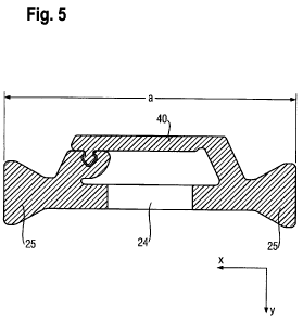
In the fourth embodiment of an insulating strip shown in Fig. 5, an in situ
extruded cover
6 (cover profile) 40 is provided for covering the intermediate spaces between
the rungs. in a view
7 corresponding to Fig. 1 c). The cover profile is integrally formed with the
strip. As viewed in a
8 cross section perpendicular to the longitudinal direction z, the cover
profile is in situ extruded as
9 a cover on one side of the rungs (as viewed in the x-direction) and its free
end (edge) is clipped
onto the other side of the rungs (as viewed in the x-direction). The clip-
connection is
11 constructed so that the clipping-in takes place in the height direction (y-
direction).
12
13 In an alternative embodiment, which is shown in Fig. 6, the clip-connection
is designed
14 in another manner, so that it is clipped-in inclined to the height
direction (y-direction) and a
traction force in the transverse direction (x-direction) retains the clip in
the engagement.
16
17 In the fifth embodiment shown in Fig. 7, the insulating strip body 20 is
provided with clip
18 heads (male clip parts) 28 on the rungs 23. These are disposed so that, in
the height direction y,
19 one clip head 28 is disposed on one side and two clip heads 28 are disposed
on the other side. As
a result, a single clip head 28 is disposed on the rung in the center in the
transverse direction x,
21 whereas the two other clip heads are disposed on the other side with
identical distances from the
22 center.
23
24 The clip heads each project by a height h3 relative to the rest of the
surface of the rungs
23 of the insulating strip body 20. The sum of the thickness hl in the height
direction y and
26 twice the projecting length h3 is preferably identical to the thickness of
the roll-in heads 25 in the
27 height direction y.
28
29 In the fifth embodiment, a cover (cover profile) 40 is constructed so that
it has three clip
retainers (female clip parts) 48, of which the two outer ones have the same
spacing as the two
31 clip heads 28 located on one side of the insulating strip body 20 and the
third clip retainer is
21925645.1 6
CA 02682644 2009-10-01
Agent Ref: 68201/00012
1 disposed in the middle between these. As is implied by Fig. 7, such covers
could be clipped onto
2 both sides of the insulating strip body 20 without differently-formed covers
being necessary.
3 The insulating strip body 20 has a substantially constant thickness hl over
a width al in the
4 transverse direction x. The width a2 of the cover 40 in the transverse
direction x is less than or
the same as this width al of the insulating strip body 20.
6
7 The cover has abutting lips 42 formed on its edges in the transverse
direction x, which
8 abutting lips 42 extend in the longitudinal direction Z. The clip retainers
(female clip parts) 48
9 have a distance h4 from the bottom of the clip retainer in the height
direction y to the outermost
point of the clip retainer, which distance h4 is less than the height h3 of
the clip head 28. The lips
11 42 end in the height direction y at the height level of the clip retainers
48 or somewhat higher
12 (see also Fig. 7 c)).
13
14 Plastic having a Young's modulus value of greater than 2000 N/mm2 is
advantageously
utilized as the material for the insulating strip. Suitable plastics are
polyamide, polyester or
16 polypropylene, for example PA66.
17
18 The thickness hl of the insulating strip bodies of all embodiments falls
within the range
19 of 1 mm to 50 mm, preferably 1 mm to 10 mm, more preferably 1 mm to 2 mm,
more preferably
1.4 to 1.8 mm. The thickness h2 of the cover is preferably less than or equal
to the thickness of
21 the insulating strip body associated therewith.
22
23 The embodiment shown in Figs. 5 and 6 is well-suited for smaller values of
a in the range
24 of 8 to 20 mm, for example, 14 mm. The thickness hl is then preferably, for
example, 1.4 mm.
The embodiment of Fig. 7 is well-suited for values of a in the range of 20 to
40 mm, e.g., 32 mm.
26 In this case, the preferred thickness hl falls in the range of 1.5 to 1.8
mm. PA66 is preferred as
27 the material for the stated widths and material thicknesses.
28
29 Because the insulating strip bodies are comprised of plastic, no metal
inserts are present,
i.e. they are formed without metal inserts.
31
21925645.1 7
CA 02682644 2009-10-01
Agent Ref: 68201/00012
1 In Fig. 8 a) an embodiment defined with regard to shear strength is
illustrated in a plan
2 view perpendicular to the longitudinal direction. The insulating strip has a
width a in the x-
3 direction in the range of 10 mm < a< 100 mm. The insulating strip has
openings 24 passing
4 through the material of the strip in the height direction (thickness
direction) y. The shape of the
openings is substantially triangular in the plan view, with corners having an
inner curvature of
6 radius R. The height of the triangle in the transverse direction x is c. The
triangles are disposed
7 in an alternating manner. This means that, in the plan view in Fig. 8 a),
one longitudinal side of
8 each triangle is respectively disposed alternately parallel adjacent to the
left side, then to the right
9 side, then again to the left side, etc. From this, it also follows that the
vertices are disposed in an
alternating manner. Rungs 23 are located between the triangles and have a
width b perpendicular
11 to the sides of the triangles that border them. The triangles are spaced by
a length e from the
12 respective outer edges in the transverse direction. From that, it results
that a = c + 2e. The
13 insulating strip has a height (thickness) h in the height direction over
its entire width, except for
14 the roll-in heads 25. The values are thus chosen as follows. For insulating
strips having a < 22
mm, c falls in the range of 7 to 10, preferably 8 mm. The radius R is < 2 mm,
preferably < 1
16 mm, more preferably 0.5 mm. This radius serves to prevent a stress
concentration and also to
17 prevent the formation of a type of bending joint. The width of the rungs is
1 to 3 mm, preferably
18 2 mm.
19
For strips having a> 22 mm, c falls in the range of 8 to 18 mm, preferably 12
mm. The
21 height h in the height direction y is 1.2 to 2.4 mm, preferably 1.8 mm. The
strip is made from
22 PA66GF25.
23
24 Fig. 8 c) shows a modification of the sixth embodiment in cross-section, in
which the
path of the strip between the two roll-in heads is not straight, as in Fig. 8
b).
26
27 Fig. 8 d) shows a seventh embodiment. The seventh embodiment differs from
the sixth
28 embodiment in that the openings are not substantially triangular, but
rather are substantially
29 rectangular. The cross-section perpendicular to the longitudinal direction
can be as shown in
Figs. 8 b) or c). The dimension specifications for a, b, c, e or R for the
sixth embodiment also
31 apply to the seventh embodiment. The length d, i.e. the dimension of the
openings in the
21925645.1 8
CA 02682644 2009-10-01
Agent Ref: 68201/00012
1 longitudinal direction z, falls in the range of 3 to 8 mm, preferably 5 mm.
This dimension d also
2 applies to the preferred maximum dimension of the triangular openings in the
sixth embodiment,
3 even though the dimension d is not shown in Fig. 8 a).
4
Fig. 8 e) shows an eighth embodiment. The eighth embodiment differs from the
sixth
6 and seventh embodiment in that the openings are circular with a diameter
having the dimension
7 c. Fig. 8 f) shows a ninth embodiment that differs from the sixth and
seventh embodiment in that
8 the openings are six-sided. The remaining specifications for the sixth and
seventh embodiments
9 also apply, as far as they are applicable, to the eighth and ninth
embodiments.
11 Fig. 9 shows, in a) in the plan view perpendicular to the longitudinal
direction and in b)
12 in the cross-section to the longitudinal direction, an insulating strip
having a so-called package-
13 design. This package-design is designed to be installed in a composite
profile as is shown in an
14 exemplary manner in the cross-section in Fig. 7 c). For this purpose, the
four roll-in heads 25 are
rolled into the corresponding four retainers, as is readily apparent from a
comparison with Fig. 7.
16 The upper insulating strip part 20a in Fig. 9 b) is thus rolled-in above in
Fig. 7 c) and the lower
17 insulating strip part 20b in Fig. 9 b) is thus rolled-in below in Fig. 7
c). Both insulating strip
18 parts are connected by a clipped-on connecting piece 20c so that, on the
one hand, a shield
19 against convention and irradiation is achieved between the inner and outer
sides of the composite
profile and, on the other hand, a plurality of hollow chambers 20d is formed.
The hollow
21 chambers 20d are sub-divided in the height direction y by a diagonal strut
20e of the connecting
22 piece 20c. As is easily recognizable in Fig. 9 a), openings 24 can be
formed with a width in the
23 transverse direction x and a longitudinal dimension d in the longitudinal
direction z and can be
24 formed in one or more insulating strip parts 20a, 20b and/or in the
connecting piece 20c. The
insulating strip parts 20a and 20b shown in Fig. 9 d) each also have outwardly-
pointing
26 projections 20f that can form the retainers for rubber seals and/or
mounting parts. These are not
27 an essential component of the depicted embodiment. The number of the
openings and the width
28 and length of the openings is not limited to the arrangement shown in Fig.
9 a).
29
The embodiment with modifications shown in Fig. 10 shows a so-called hollow
chamber
31 profile. In such a hollow chamber profile, hollow chambers are located
between the roll-in
21925645.1 9
CA 02682644 2009-10-01
Agent Ref: 68201/00012
1 projections 25 in the transverse direction x. In Fig. 10 d), the cross-
section of a conventional
2 hollow chamber profile is shown. As can be readily derived from the
comparison with the cross-
3 section of the eleventh embodiment in Fig. 10 b), the difference essentially
consists in that the
4 wall in the central hollow chamber between the rungs 23 is removed, i.e.
openings 24 are
formed. The openings have a width g in the transverse direction x and a length
dimension d in
6 the longitudinal direction z. In particular for hollow chamber profiles
having a width a of > 25
7 mm, the specifications for c) of the sixth to ninth embodiments can also be
utilized for g). In the
8 modification in Fig. 10 c), an opening 24 is formed only on one side of the
hollow chambers.
9 According to the modifications, which are shown in Figs. 10 e) and f), the
part of the hollow
chamber profile, in which one or more openings 24 are formed, is filled with a
foam as a filling
11 material. This foam is preferably a PUR foam that has a lower heat
conductivity coefficient than
12 the material formed for forming the insulating strip body.
13
14 Figs. 11 a) to f) show modifications of the sixth to ninth embodiments in
views having
the same numbering a) to f), in each of which a projection 28 is formed that
projects from the
16 insulating strip body substantially in the height direction y. This
projection 28 principally serves
17 to obstruct convection and radiation. The height of the projection 8 in the
height direction y is
18 chosen accordingly. In Fig. 7 c), the installation of an insulating strip
having such a projection
19 28 is indicated below in a dashed manner. If the insulating strip shown
above in Fig. 7 c) has
one or more corresponding projections 28, which overlap with the lower
projection 28 as viewed
21 in the transverse direction x, then a particularly effective hindering of
the convection and
22 radiation is achieved. Figs. 12 b), c) and d) show modifications of
insulating strips having two
23 such projections 28.
24
All of the embodiments shown in Figs. 8 to 12 are preferably provided with in
situ
26 extruded covers of the type shown in Figs. 5, 6 or more preferably with
clip projections and/or
27 clip retainers of the type shown in Fig. 7. In the alternative, it is also
possible to provide films
28 for covering the openings or to perform a filling with a material of lesser
heat conductivity than
29 the material of the insulating strip body. The at least partially or
entirely clipped-on covers or, if
applicable, films are preferred.
31
21925645.1 10
CA 02682644 2009-10-01
Agent Ref: 68201 /00012
1 Hard-PVC, PA, PET, PPT, PA/PPE, ASA and PA66 are possibilities for the
material of
2 the insulating strip body and PA66GF25 is preferred. Foams made of
thermosetting plastics,
3 such as PU having an appropriate density, are possibilities, preferably
foams of lower density
4 (0.01 to 0.3 kg/1).
6 Further applications of ladder-like profiles are directed to achieving a low
shear strength
7 (high longitudinal movability). In another application, openings are
provided only to reduce the
8 heat conductivity when a known, highly-conductive metal insert is used.
9
In the preferred embodiments having partially in situ extruded covers that are
clipped
11 onto the other side, wherein embodiments with completely clipped-on covers
are particularly
12 preferred, and also in the embodiments having adhered-on or laminated-on
films, each for
13 covering the openings, it is been determined in a surprising way for the
entire or partially
14 clipped-on covers that these only insubstantially influence the so-called U-
values, i.e. the heat
isolating characteristics of the insulating strip, as compared to not-covered
versions. Thus,
16 experiments with a solid strip having a cross-section of the type shown in
Fig. 8 b), i.e. a strip
17 without openings, which strip has a width of 25 mm, a height h of 1.8 mm
and PA26GF25 as the
18 material, resulted in a U-value (W/m2K) of 2.4.
19
An insulating strip of the type shown in Fig. 8 d) having c = 8 mm, d = 5 mm
and b = 2
21 mm resulted in a U-value of 2.15 W/m2K without covering. A corresponding
strip having
22 clipped-on covers according to Fig. 7 had a U-value of 2.25 W/m2K. The
measurements were
23 performed in a so-called "hot-box", wherein a system with 25 mm wide, flat
insulating strips was
24 utilized as the initial system, which insulating strips were not exchanged
during the course of the
experiment. Therefore, the improvement of the U-values should be even better
in reality.
26
27 Even though the cause of this effect is not completely clear, it is
probably due to the
28 design of the clip connections and thus the heat transmission path that is
severely obstructed by
29 the cover.
21925645.1 11
CA 02682644 2009-10-01
Agent Ref: 68201/00012
1 For the embodiments with the hollow chambers shown in Figs. 9, 10, which are
already
2 utilized for systems having excellent insulating properties, these
properties can be further
3 improved. The usage of convention and/or radiation shielding projections 28
likewise increases
4 this effect.
6 It is explicitly emphasized that all features disclosed in the description
and/or the claims
7 should be regarded as separate and independent of each other for the purpose
of the original
8 disclosure as well as for the purpose of restricting the claimed invention,
independent of the
9 combination of features in the embodiments and/or the claims. It is
explicitly stated that all
specifications of ranges or of groups of units disclose all possible
intermediate values or sub-
11 group of units for the purpose of original disclosure as well as for the
purpose of restriction of
12 the claimed invention, in particular also as a limit of a range indication.
13
21925645.1 12