Note: Descriptions are shown in the official language in which they were submitted.
CA 02682688 2009-10-01
WO 2008/130295 PCT/SE2007/050252
A WAVE POWER UNIT, A BUOY, USE OF A WAVE POWER UNIT AND A
METHOD FOR PRODUCING ELECTRIC ENERGY
Field of invention
The present invention in a first aspect relates to a wave power unit includ-
ing a buoy adapted to float on a water surface, an electric generator and
mechani-
cal connection means connecting the buoy to the electric generator.
In a second aspect, the invention relates to a buoy for a wave power unit.
In a third and a fourth aspect, the invention relates to the use of the in-
vented wave power unit and to a method for producing electric power
respectively.
Background on the invention
Wave power energy has developed to be one of the renewable energy
sources that can be of great importance for meeting the challenge to replace
the
traditional energy sources. The total wave power energy resources around the
costs of the continents is huge and the technically exploitable part thereof
is also
considerable.
As is the case for many of the renewable energy sources, the economy for
converting this energy into usable electric energy is the crucial aspect. In
order to
achieve that electric energy produced from wave energy will become competitive
with the traditional ways of producing energy it is necessary to technically
and
economically optimize each link in the production chain. The present invention
is
focused on optimizing the design of the buoy used in a wave power unit.
Wave power units for producing electric energy on a larger scale are dis-
closed e.g. in WO 03/058055.
Traditionally the buoy of such a wave power unit has been formed as a
quite compact body having the shape of a sphere, a flat cylinder or a double
cone.
No particular attention has been paid to the fact that the shape of the buoy
affects
the efficiency of the buoy to convert the wave energy into mechanical energy.
CA 02682688 2009-10-01
WO 2008/130295 PCT/SE2007/050252
2
The object of the present invention is to solve the problem how to shape
the buoy in order to achieve a high efficiency with respect to converting the
wave
energy into usable mechanical energy.
Summary of the invention
The above mentioned problem has according to the first aspect of the in-
vention been solved by providing a wave-power unit with a buoy which when
float-
ing on a water surface and when seen in a direction perpendicular to the water
surface has the shape of a closed loop enclosing an inner opening.
For a given floating force of the buoy this results in a larger extension in
the side directions i.e. in the directions of the water surface. This is
advantageous
regarding the efficiency for converting the wave energy. If the large
extension in
the side directions would have been achieved simply by making the buoy thin
and
wide like a thin plate other problems would occur. By making the buoy as a
closed
loop enclosing an inner opening, e.g. shaped as a thorus, the water can pass
through the centre of the buoy which considerably reduces these problems, and
improves the dynamic of the buoy. The advantages of a buoy having this shape
are particularly accentuated when the waves are high and strong. The loop
shape
also provides a high mechanical strength which is necessary for coping with
the
high forces affecting the buoy.
di:I)
The energy that is converted in the generator is proportional to ¨ which
df
is dependent on F - v, where F is the force affecting the buoy and v its
velocity in
the vertical direction. i.e. in the direction of the force. With a sufficient
buoyancy of
the buoy the force F is at a high level. The problem is to achieve as high
velocity
as possible. With the shape of the buoy according to the invention the
velocity be-
comes considerably increased in relation to traditional buoys.
By the invention it is further achieved that
- the water masses above the buoy when being overflown by high
breaking
waves are minimized,
CA 02682688 2009-10-01
WO 2008/130295 PCT/SE2007/050252
3
- a high side surface against waves can be maintained in spite of a large
side extension of the buoy,
- it is possible to maintain a low static buoyancy with high dynamic wave
absorption at low and middle sized waves, achieved by a relatively large
floating surface in relation to a low displacement,
- the inner opening also secures that extremely high waves do not result
that the buoy will come under the water surface due to the fact that the
water can pass through the inner opening upwards.
A wave power unit where the buoy has the shape according to the inven-
tion therefore results in a higher efficiency in converting the wave energy
into a
mechanical energy of the kind that can be used for generating electric energy.
The simplest and in many respects most efficient way of converting the
mechanical energy into electric energy is to mechanically connect the buoy
direct
to the rotor of the buoy such that the movements of the buoy moves the rotor.
If
the generator is a rotary generator this movement of course has to be
transferred
into rotary motion. This is superfluous in case the generator is a linear
generator,
where the linear reciprocating rotor directly can be connected to the buoy via
a
wire or the like.
Although direct transfer of the buoy movements to the movements of the
rotor of the generator has many advantages the present invention of course is
ap-
plicable when there are various intermediate steps of converting the
mechanical
energy, e.g. a pump driven by the buoy, a hydraulic motor driven by the pump
and
a generator driven by the hydraulic motor.
According to a preferred embodiment of the invented wave power unit, the
buoy thereof includes a floating body having said shape of a closed loop
enclosing
an inner opening.
Providing the floating body per se with that shape results in a very simple
buoy construction which is easy to manufacture.
CA 02682688 2009-10-01
WO 2008/130295
PCT/SE2007/050252
4
According to a further preferred embodiment the floating body includes a
plurality of sections directly connected to a each other.
Thereby a very economical module concept for the manufacture of the
floating body is achieved.
According to a further preferred embodiment each section is a straight
pipe, and each pipes is water tight connected to adjacent pipes.
Building up the floating body with sections formed as straight pipes makes
the module concept optimized regarding the economical aspects of the manufac-
ture. By forming water tight connection between the pipes a continuous loop-
shaped hollow body is formed, which is a very effective floating body.
According to a further embodiment of the invention each pipe has circular
cross section.
This shape is advantageous with respect to the various flow paths of water
to which the buoy will be exposed when affected by waves. Furthermore the
effec-
tive floating volume in relation to the required material becomes maximized.
Fi-
nally, the use of circular pipes is advantageous regarding manufacturing
economy.
According to a further embodiment of the invention each pipe is made of
steel.
Taking into account the material cost, the mechanical strength of the ma-
terial and the possibility to resist corrosion in sea water, steel is a very
advanta-
geous alternative, in particular stainless steel.
According to a further preferred embodiment the pipes are welded to each
other.
Thereby a strong and reliable connection that is water tight is achieved at
reasonable low cost.
According to a further preferred embodiment the number of sections is
three to twelve.
CA 02682688 2009-10-01
WO 2008/130295 PCT/SE2007/050252
The fewer the sections are the less expensive the manufacture of the
floating body becomes. Three is of course the minimum to form a closed loop.
On
the other hand, the higher the number of sections is, the more harmonic will
the
behaviour of the floating body be regarding the flow dynamics when exposed to
5 the
water waves. In most cases the balance of these considerations will be within
the specified range, normally within the closer range from four to eight. A
floating
body made up by six sections appears in many cases be the most favourable bal-
ance.
According to a further preferred embodiment all sections have the same
dimensions.
Thereby a high degree of symmetry in various respects will be achieved
for the floating body, which makes its optimized for its purpose.
According to a further preferred embodiment the floating body is a regular
polygon.
This embodiment represents the highest degree of symmetry of the float-
ing body, thereby maximizing the efficiency of the buoy.
According to a further preferred embodiment the floating body is made of a
material having a density lower than the density of water.
This embodiment has the advantage of eliminating the problem to secure
water-tightness.
According to a further preferred embodiment the floating body is a thorus
This is a simple and harmonic shape of the floating body which makes the
buoy stabile an symmetric.
According to a further preferred embodiment the thorus has circular cross
section.
The circular cross section provides a minimum of disturbance when waves
are flowing across it or through it.
CA 02682688 2009-10-01
WO 2008/130295 PCT/SE2007/050252
6
According to a further preferred embodiment the buoy includes a plurality
of floating bodies connected to each other by a plurality of connecting
sections
such that the floating bodies and the connecting sections together form said
closed loop enclosing an inner opening.
This embodiment simplifies the problem to obtain water-tightness since
each floating body can be made as a closed entity. There is thus no need to
con-
nect hollow sections watertight to each other.
According to a further preferred embodiment each floating body has the
shape of a sphere or a cylinder.
Also with this embodiment it is attained that the disturbance from the
waves when flowing across the floating bodies or through the buoy will be low.
According to a further preferred embodiment each connecting section es-
tablishes a rigid connection between adjacent floating bodies.
Thereby the buoy will be stable and move as a single unit.
According to a further preferred embodiment the connection means in-
cludes at least three fastening devices connected to the buoy at different
locations.
Thereby the transfer of the movements to the generator will be most effec-
tive since the complete kinetic energy of the buoy is made use of. Preferably
the
number of fastening devices are three and located at the corners of a regular
tri-
angle.
According to a second aspect of the invention the object is achieved in
that a buoy for a wave power unit has the specific features that the buoy when
floating on a water surface and when seen in a direction perpendicular to the
water
surface has the shape of a closed loop enclosing an inner opening.
According to preferred embodiments of the invented buoy it includes the
features corresponding to the features of the buoy in the various preferred em-
bodiments of the wave power unit set out above.
CA 02682688 2009-10-01
WO 2008/130295 PCT/SE2007/050252
7
The invented buoy and the preferred embodiments thereof have the corre-
sponding advantages as mentioned above for the invented wave power unit and
the preferred embodiments thereof.
According to the fourth aspect of the invention the invented method for
producing electric energy includes the specific measure that the electric
energy is
produced by means of a wave power unit according to the present invention or
any
of the preferred embodiments thereof.
The invented method as well as the invented use according to the third
aspect of the invention also has the same advantages as mentioned above for
the
invented wave power unit and the preferred embodiments thereof.
The invention will be described more in detail through the following advan-
tageous examples and with reference to the accompanying drawings.
Brief description of the drawings
Fig. 1 is a schematic view from the side of a wave power unit in accor-
dance with the invention.
Fig. 2 is a top view of the buoy in fig. 1.
Fig. 3 is a top view of a second example of a buoy.
Fig. 4 is a cross section through the buoy in fig. 3.
Fig. 5 is a top view of a third example of a buoy.
Fig. 6 is a section along the line VI-VI of fig. 5.
Fig. 7-10 are top views of further examples of a buoy.
Description of advantageous embodiments of the invention
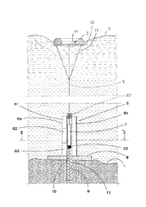
Fig. 1 illustrates the principle of a wave-power unit in accordance with the
invention. A buoy 3 is arranged to float on the surface 2 of the ocean. Waves
im-
part a to-and-fro vertical movement to the buoy 3. A linear generator 5 is an-
chored at the sea bed via a base plate 8 secured in the bottom. The plate may
be
CA 02682688 2009-10-01
WO 2008/130295 PCT/SE2007/050252
8
of concrete. The stator 6a, 6c of the linear generator is secured to the base
plate
8. The stator consists of four vertical pillar-like laminated stacks, only two
of which
are visible in the figure. The rotor 7 of the generator is arranged between
the
laminated stacks and is connected to the floating body 3 by a cable 4. The
rotor 7
is of permanently magnetic material.
The base plate 8 has a centrally arranged hole 10 and, concentrically with
this, a bottom recess 9 is made in the sea bed. The recess 9 may suitably be
lined. A tension spring 11 is secured at the lower end of the recess 9 and the
other end of the spring is attached to the lower end of the rotor 7. The
diameter of
the hole 10 in the base plate 8 and of the recess 9 is such that the rotor 7
can
move freely through them.
Each laminated stack 6a, 6c is composed of a number of modules. In the
example illustrated the laminated stack 6a is marked to indicate how it is
divided
into three vertically arranged modules 61, 62, 63,
When the buoy 3 moves up and down due to the movement of the waves
in the surface 2 of the ocean, this movement is transmitted via the cable 4 to
the
rotor 7 which thus acquires an equivalent to-and-from movement between the
laminated stacks. Current is thus generated in the stator windings. The recess
9
permits the rotor to pass the whole stator in its downward movement. The
tension
spring 11 gives added force to the downward movement so that the cable 4 is
kept
taut at all times.
The spring may also be designed so that in certain situations it can also
exert an upward force. The spring rate of the spring can be controlled by a
control
means 28 so that resonance is achieved for as much of the time as possible.
The stator is entirely or partially impregnated with VPI or silicon so that it
can withstand the salt water.
When the buoy floats on the waves it will drift in the horizontal direction
such that the cable will incline in relation to the vertical direction. In
order to avoid
that this results in that the rotor 7 will be inclined a guiding device 30 for
the cable
4 is provided at the entrance of the cable in the linear generator. Thereby
the rotor
CA 02682688 2009-10-01
WO 2008/130295 PCT/SE2007/050252
9
7 will maintain a strict vertical motion and be centred within the stator even
when
the cable is inclined.
The buoy 3 is a thorus leaving an inner central opening 14. The cross sec-
tional shape of the thorus is a polygon, formed from a rectangular base shape
and
with tapering inner surfaces at the top and the bottom and a tapering outer
surface
at the top.
The cable 4 is connected to the buoy via three minor cables 12 each being
secured to the buoy through a fastening device 13. The fastening devices 13
are
located in a 1200 relationship to each other.
Further details regarding the function of a wave power unit in general for
transforming the movements of the cable into electrical energy is not in focus
for
the present invention, and that function is generally known. For the
understanding
of that process reference is made to WO 03/058055.
It is to be understood that the design of the linear electric generator can be
of different types than the one described in relation to Fig. 1. The present
invention
is also applicable if the linear generator is replaced by a rotary electric
generator. It
is also within the frames of the present invention that various mechanical
conver-
sions of the energy transferred by the cable 4 can take place before it is
used for
producing electric energy.
In figure 2 the buoy is shown in a view from above.
Fig. 3 and 4 illustrates an alternative embodiment of a thorus shaped buoy
3a, having a circular cross section.
The buoys in Fig. 1 to 4 are illustrated as homogenous bodies which
means that the material is a light weight material, i.e. having a density
lower then
that of water. In most cases, however, it is more suitable to make the thorus
shaped buoy s a hollow body made of steal. The cavity can be void. i.e. air or
it
can be filled with a light weight material, e.g. a porous polymer.
CA 02682688 2014-03-11
=
WO 2008/130295 PCT/SE2007/050252
Fig. 5 and 6 illustrates a further example of the shape of the buoy. In this
case the buoy 3b is built up of six pipes 15 welded together to form a regular
hexagon.
Fig. 7 illustrates an example similar to that of figures 5 and 6. In this ex-
s ample the buoy 3c is built up of four pipes forming a rectangle.
Fig. 8 illustrates an example where the buoy is made up by a horse-shoe
shaped floating body 16 and a connection rod 17.
In the example illustrated in figure 9 the buoy 3e is made up by four float-
ing bodies 16a, e.g. pipes which are closed at its ends and four connecting
rods
10 17a.
Finally figure 10 illustrates an example where the buoy is made up by
eight spherical floating bodies 16b connected by connecting rods 17b.
As can be understood by the above examples, the buoy can have many
various shapes and be constructed in various ways.
Typical data for a buoy with thorus shape, such as the one in figures 1 and
2 can be:
Deplacement: 9.5 m3
External diameter: 4 m
Internal diameter: 2 m
Height: 0.8 m
Weight: 1500 ¨ 2000 kg
These data are only for giving a general impression of the size that nor-
mally comes in question and are of course in no way limiting.