Note: Descriptions are shown in the official language in which they were submitted.
CA 02682718 2013-04-30
HIGH FREQUENCY OSCILLATION RESPIRATORY THERAPY DEVICE
Background of the Invention
1011
The present invention relates to respiratory therapy devices. More
particularly, it
relates to percussive respiratory devices that deliver high frequency pulses
of air to a
patient during the patient's inspiratory and expiratory cycles.
[02] A wide variety of respiratory therapy devices are currently available
for assisting,
treating, or improving a patient's respiratory health. For example, positive
airway pressure
(PAP) has long been recognized to be an effective tool in promoting bronchial
hygiene by
facilitating improved oxygenation, increased lung volumes, and reduced venous
return in
patients with congestive heart failure. More recently, positive airway
pressure has been
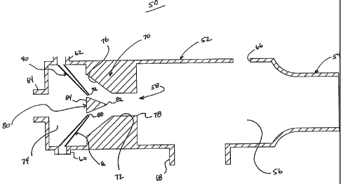
recognized as useful in promoting mobilization and clearance of secretions
(e.g., mucus)
from a patient's lungs. In this regard, positive airway pressure in the form
of high
frequency oscillation (HFO) of the patient's air column is a recognized
technique that
facilitates secretion removal. In general ternis, FIFO reduces the viscosity
of sputum in
vitro, which in turn has a positive effect on clearance induced by an in vitro
simulated
cough. HFO can be delivered or created via a force applied to the patient's
chest wall (i.e.,
chest physical therapy (CPT), such as an electrically driven pad that vibrates
against the
patient's chest), or by applying forces directly to the patient's airway
(i.e., breathing
treatment, such as high frequency airway oscillation). Many patients and
caregivers prefer
the breathing treatment approach as it is less obtrusive and more easily
administered. To
this end, PAP bronchial hygiene techniques have emerged as an effective
alternative to
CPT for expanding the lungs and mobilizing secretions.
[03] Various treatment systems are available for providing the respiratory
therapy
described above (as well as other therapies and/or ventilation).
For example,
intrapulmonary percussive ventilation (IPV) therapy relates to HFO devices
that deliver
pulses of air into the patient's airway opening. In general terms, an IPV
system includes a
hand-held device establishing a patient breathing circuit to which a source of
positive
pressure gas (e.g., air, oxygen, etc.), is fluidly connected. The pressure
source and/or the
device further include appropriate mechanisms (e.g., control valves provided
as part of a
driver unit apart from the hand-held device) that effectuate intermittent flow
of gas into the
patient breathing circuit, and thus percussive ventilation of the patient's
lungs. With this
approach, the patient breathes through a mouthpiece that delivers high-flow,
"mini-bursts"
- 1 -
CA 02682718 2014-04-29
of gas. During these percussive bursts, a continuous airway pressure above
ambient is
maintained, while the pulsatile percussive gas flow periodically increases
airway pressure
(e.g., the gas flow cycles the delivered pressure). Each percussive cycle can
be
programmed by the patient or caregiver with certain systems, and can be used
throughout
both inspiratory and expiratory phases of the breathing cycle. Examples of IPV
devices
include IPV ventilator device (from PercussionAire Corp. of Sandpoint, ID),
IMP 2TM
(from Breas Medical of Molnlycke, Sweden), and PercussiveNebTM System (from
Vortran
Medical Technology, Inc., of Sacramento, CA). Also, U.S. Patent No. 7,191,780
describes
an WV-type treatment apparatus, connectable to a source of pressurized gas,
that requires a
shrouded, fixed venturi tube for delivering the desired therapy.
104] In light of the promising nature of 1PV therapy devices, any
improvements to known
designs, such as enhanced performance, long-term reliability, reduced
manufacturing costs,
ease of operation, etc., will be well received.
Summary
1051 According to a first aspect, a respiratory therapy device comprises a
housing defining
a primary passageway having a patient interface side, a flow diverter
structure maintained
by the housing in fluid communication with the primary passageway opposite the
patient
interface side, wherein the flow diverter structure is characterized by the
absence of a
venturi tube, a high frequency (HF) pressure port maintained by the housing
and
configured for fluid connection to a source of oscillatory gas flow, the HF
port being
fluidly associated with the flow diverter structure, an entrainment port
maintained by the
housing and openable to ambient air, the entrainment port being fluidly
associated with the
flow diverter structure, wherein the device is configured such that flow
characteristics of
gas flow from said HF port is altered upon interacting with the flow diverter
structure to
create a pressure drop for drawing in the ambient air through the entrainment
port in
delivering a percussive pressure therapy to the patient side of the primary
passageway, and
wherein the flow diverter structure comprises a neck region having a tapering
portion that
tapers radially inward toward the primary passageway and a diverter body
disposed within
the tapering portion, the diverter body having a shape that tapers proximally
toward the
primary passageway from a distal end of the diverter body.
1061 In an example embodiment according to the above aspect, the flow
diverter structure
may move in response to pressure pulses delivered via the HF port in affecting
gas flow
- 2 -
CA 02682718 2014-04-29
from the CPP port toward the primary passageway. The CPP port can be the same
port as
the HF port in some constructions. In some embodiments, the HF port is
connected to or
forms a nozzle having a nozzle end that faces the flow diverter structure,
with the flow
diverter structure including a neck region forming a reduced-size passage
immediately
adjacent the primary passageway.
[071 According to another aspect, a respiratory therapy system comprises a
respiratory
therapy device including a housing defining a primary passageway having a
patient
interface side, a flow diverter structure maintained by the housing in fluid
communication
with the primary passageway opposite the patient interface side, wherein the
flow diverter
structure is characterized by the absence of a venturi tube, a HF pressure
port maintained
by the housing and fluidly associated with the flow diverter structure, an
entrainment port
maintained by the housing and openable to ambient air, the entrainment port
being fluidly
associated with the flow diverter structure, and a source of oscillatory gas
flow; wherein
the source of oscillatory gas flow is fluidly connected to the 1-IF pressure
port, wherein the
device is configured such that flow characteristics of gas flow from the
sources of
oscillatory gas flow are altered upon interacting with the flow diverter
structure to create a
pressure drop for drawing in the ambient air through the entrainment port and
to deliver
percussive pressure therapy to the patient interface side of the primary
passageway, and
wherein the flow diverter structure comprises a neck region having a tapering
portion that
tapers radially inward toward the primary passageway and a diverter body
disposed within
the tapering portion, the diverter body having a shape that tapers proximally
toward the
primary passageway from a distal end of the diverter body. During operation of
an
example embodiment of such a system, oscillatory gas flow from the source is
delivered to
the respiratory therapy device and impacted by the flow diverter structure to
cause
entrainment of ambient air with the pressure pulses delivered to the patient
interface side,
and thus the patient.
[08] According to yet another aspect, a respiratory therapy device
comprises a housing
defining a primary passageway having a patient interface side, a positive
pressure port
maintained by the housing and configured for fluid connection to a source of
continuous
positive pressure gas flow, a flow diverter structure including an obstruction
body movably
maintained within the housing, fluidly between the positive pressure port and
the primary
passageway, a HF pressure port maintained by the housing and fluidly connected
to the
flow diverter structure, wherein the HF pressure port is configured for fluid
connection to a
source of oscillatory gas flow such that a pressure pulse delivered to the HF
pressure port
- ,3 -
CA 02682718 2014-04-29
causes movement of the obstruction body, and an entrainment port maintained by
the
housing and openable to ambient air, the entrainment port being fluidly
associated with the
flow diverter structure, the device being configured such that flow
characteristics of gas
flow from the positive pressure port are selectively altered upon interaction
with the
obstruction body to deliver a percussive pressure therapy to the patient
interface side of the
primary passageway; and wherein the flow diverter structure comprises a neck
region
having a tapering portion that tapers radially inward toward the primary
passageway and a
diverter body disposed within the tapering portion, the diverter body having a
shape that
tapers proximally toward the primary passageway from a distal end of the
diverter body.
In some embodiments, the obstruction body is longitudinally movable relative
to a central
axis of the CPI' port. In other embodiments, the obstruction body is rotatably
mounted
within the housing.
Brief Description of the Drawings
1091 FIG. 1 is a block diagram of a percussive respiratory therapy device
in accordance
with aspects of the present disclosure;
[10] FIG. 2 is a simplified, cross-sectional illustration, with portions
drawn schematically,
of one embodiment of a respiratory therapy device;
[11] FIGS. 3A and 3B are simplified, cross-sectional illustrations, with
portions drawn
schematically, of an alternative configuration of the device of FIG. 2 and
showing use
thereof in generating a percussive therapy;
1121 FIG. 4 is a simplified, cross-sectional illustrations, with portions
drawn
schematically, of another embodiment respiratory therapy device;
1131 FIG. 5 is a simplified, cross-sectional illustration, with portions
drawing
schematically, of another embodiment respiratory therapy device;
[141 FIGS. 6A and 6B are simplified, cross-sectional illustrations, with
portions drawn
schematically, of another embodiment respiratory therapy device; and
[15] FIGS. 7A and 7B are simplified cross-sectional illustrations, with
portions drawn
schematically, of another embodiment respiratory therapy device.
- 4 -
CA 02682718 2013-04-30
Detailed Description
1161 General features of a respiratory therapy device 20 in accordance
with aspects of the
present disclosure is shown in block form in FIG. 1. In general terms, the
respiratory
therapy device 20 operates to deliver high frequency pulses of air to a
patient during the
patient's inspiratory and expiratory cycles when connected to a source of
oscillatory gas
flow 22. In this regard, the source of oscillatory gas flow 22 can assume a
variety of forms
known in the art, and generally includes a flow interrupter valve or similar
structure
capable of generating an oscillatory flow of positive pressure gas (e.g., air,
oxygen, etc.),
such as that described in U.S. Patent No. 4,805,613. In other embodiments, the
therapy
device 20 can be configured to establish an oscillatory flow when acting upon
a constant
flow of gas such that the source 22 can be a source of constant gas flow. With
this in
mind, the respiratory therapy device 20 includes a housing 24 maintaining
and/or forming
various components such as a high frequency flow port (HF port) 26, one or
more
entrainment ports 28, a flow diverter structure 30, one or more exhaust
apertures 32, and a
mouthpiece 34. In addition, the respiratory therapy device 20 includes a
constant positive
pressure port (CPP port) 36 and, optionally, a nebulizer port 38.
[17] Details on the various components are provided below in connection
with
embodiments being described. In general terms, however, the flow diverter
structure 30 in
accordance with the present disclosure can assume a variety of forms as
described below,
and in some embodiments is generally characterized as not being or including a
venturi
tube (fixed or sliding), where a "venturi tube" is defined to be a body
including a gradually
decreasing or converging diameter nozzle section that extends to a throat,
followed by a
gradually increasing or expanding diameter diffuser section. The flow diverter
structure 30
is fluidly connected to a primary passageway formed by the housing 24, as is
the
mouthpiece 34. The mouthpiece 34 serves as a patient interface through which
the patient
breathes and can assume a variety of forms. In more general terms, then, the
primary
passageway of the housing 24 can be defined as having a patient interface side
40 at which
the mouthpiece 34 is connected.
[18] During use, high frequency oscillatory gas flow is directed from the
source 22 to the
HF port 26 and then toward the flow diverter structure 30 (represented by
arrows in FIG.
I).
- 5 -
CA 02682718 2013-04-30
High velocity flow from the HF port 26 (e.g., a nozzle) creates a pressure
drop within the
housing 24 that, in turn, entrains ambient air via the entrainment port(s) 28.
Interaction
between high velocity flow and the flow diverter structure 30 causes gas flow
to be
directed toward the mouthpiece 34. In some embodiments, the flow diverter
structure 30
operates to affect gas flow from the HF port 24 in a pulse-like manner,
creating a
percussive gas flow/pressure effect toward the mouthpiece 34. With these
embodiments,
then, a constant input pressure flow to the housing 24 can be used, thus
eliminating a need
for the source of oscillatory gas flow 22. In other embodiments, the flow
diverter 30
operates in response to delivered oscillatory gas flow, in turn acting upon a
separate,
constant flow of gas to generate oscillatory pressure pulses that are
delivered to the
mouthpiece 34/patient.
Regardless, oscillatory pressure pulses (including entrained
ambient air) are delivered to the patient via the mouthpiece 34. Between
pulses, the
exhaust aperture(s) 32 and the entrainment port(s) 28 allow the patient to
breathe in and
out of the device 20 without significant resistance.
119]
The CPP port 36 can be connected to a source of positive pressure gas (not
shown) to
enhance the respiratory therapy provided by the device 20 (e.g., generate
appropriate
positive expiratory pressure (PEP), etc.), provide a primary gas flow that is
acted upon by
the flow diverter 30, and/or to provide other therapies (e.g., constant
positive airway
pressure (CPAP)). Similarly, the optional nebulizer port 38 can be connected
to a
nebulizer (not shown) to introduce aerosolized medication into the gas flow
delivered to
the patient. In some embodiments, the nebulizer port 38 is physically
positioned between
the flow diverter structure 30 and the mouthpiece 34 such that the aerosolized
airflow does
not directly interact with the flow diverter structure 30 in a manner that
might otherwise
result in undesirable aerosol "knock-down".
[20]
With the above general construction in mind, FIG. 2 schematically illustrates
one
embodiment of a respiratory therapy device 50 in accordance with principles of
the present
disclosure. The device 50 includes a housing 52 maintaining or connectable to
a
mouthpiece 54 (referenced generally) adapted for placement in a patient's
mouth and
through which the patient can breathe. The housing 52 further forms a primary
passageway 56 through which gas flow from a flow diverter structure 58 is
fluidly directed
to the mouthpiece 54. In this regard, the housing 52 further includes or forms
an HF port
60, a CPP port 62, and one or more entrainment ports 64. Gas flow through the
ports 60-64
is directed to the flow diverter
- 6 -
CA 02682718 2009-10-01
WO 2008/122045 PCT/US2008/059162
structure 58. Finally, the device 50 optionally includes one or more exhaust
apertures 66
and/or a nebulizer port 68. As described below, the exhaust aperture 66 and
the nebulizer
port 68 can be combined and/or provided as part of a singular structure that
may include one
or more additional valves.
[21] The flow diverter structure 58 includes, in some embodiments, a neck
region 70
formed in or by the housing 52. The neck region 70 defines a reduced-size
passage 72, and
fluidly connects the primary passageway 56 with a chamber 74. More
particularly, the
reduced-size passage 72 has a smaller cross-sectional area (e.g., diameter) as
compared to
that of the chamber 74 and the primary passageway 56. The reduced-size passage
72 is
defined by an inlet side 76 and an outlet side 78. As shown in FIG. 2, the
inlet side 76 tapers
in cross-sectional area (or diameter) from the chamber 74 at which the ports
60-64 are
formed. The outlet side 78 has a constant diameter in extension from the inlet
side 76 to the
primary passageway 56. In addition, the flow diverter structure 58 can include
a diverter
body 80 centrally positioned within the reduced-size passage 72, adjacent the
inlet side 76.
The diverter body 80 includes or defines a leading end 82 and a trailing end
84, with the
diverter body 80 tapering in size or diameter from the trailing end 84 to the
leading end 82.
With this construction, the diverter body 80 affects airflow from the HF port
60 and the CPP
port 62 as described below. In other embodiments, the diverter body 80 can be
eliminated.
[22] The HE port 60 is adapted to be fluidly connected to the source of
oscillatory gas flow
22 (FIG. 1), for example via appropriate tubing (not shown). In addition, the
HF port 60 is
fluidly connected to or forms an HF nozzle 86. The HE nozzle 86 terminates at
a nozzle end
88, and is configured to generate jet gas flow. In this regard, the nozzle end
88 "faces" the
diverter body 80 such that jet flow from the HF port 60 (and thus from the
source of
oscillatory gas flow 22) impinges upon the diverter body 80.
[23] The CPP port 62 is similarly constructed for fluid connection to a
source of
continuous or constant positive pressure gas (not shown). The CPP port 62 is
fluidly
connected to or forms a CPP nozzle 90 terminating at a nozzle end 92. The CPP
nozzle 90
converts gas flow through the CPP port 62 into jet flow, with the nozzle end
92 "facing" the
diverter body 80. Thus, gas flow through and from the CPP nozzle 90 impinges
upon the
diverter body 80.
- 7 -
CA 02682718 2009-10-01
WO 2008/122045 PCT/US2008/059162
[24] The entrainment port(s) 64 is, in some embodiments, formed along the
chamber 74,
and allows for passage of gas into and out of the chamber 74, and thus the
housing 52. In this
regard, the entrainment port(s) 64 is fluidly associated with the flow
diverter structure 58 to
promote entrainment of ambient air into the gas flow otherwise generated at
the flow diverter
structure 58. In other embodiments, the entrainment port(s) 64 can be located
at other
locations relative to the housing 52. For example, the entrainment port(s) 64
can be formed
or located along the neck region 70.
[25] With the above configuration, the nozzles/jets 86, 90 converge at or
along the flow
diverter structure 58. Thus, and as described below, the flow diverter
structure 58 ensures
that gas flow streams from the nozzles 86, 90 are directed toward the primary
passageway 56
(and thus the patient) and that adequate ambient air entrainment (via the
entrainment port(s)
64) is produced.
[26] The exhaust aperture 66 can simply be an orifice formed in the housing
52 adjacent
the mouthpiece 54, establishing an ambient opening to the primary passageway
56. In some
embodiments, a valve (not shown), such as a one-way valve, can be assembled to
the exhaust
aperture 66, operating to selectively control gas flow to and/or from the
primary passageway
56. For example, the valve can operate to only permit release of gas from the
primary
passageway 56 during a patient's expiratory breath.
[27] Where provided, the nebulizer port 68 is adapted for connection to a
nebulizer (not
shown), such as a high-performance entrainment nebulizer available under the
trade
designation Pan LC Star, although any other nebulizer arrangement capable of
generating
aerosolized medication can be employed. Regardless, the nebulizer port 68 is
formed
adjacent the mouthpiece 54 (and thus "downstream" of the flow diverter
structure 58). With
this positioning, aerosolized entrainment within the gas flow being delivered
to the
mouthpiece 54/patient can occur without resulting in significant aerosol knock-
down within
the flow diverter structure 58. Further, a one-way valve (not shown) can be
provided to
ensure desired airflow from the nebulizer into the primary passageway 56.
Alternatively, the
nebulizer, and thus the nebulizer port 68, can be eliminated.
[28] Operation of the respiratory therapy device 50 is shown in the
illustrations of FIGS.
3A and 3B. A constant flow of positive pressure gas is delivered to the flow
diverter
- 8 -
CA 02682718 2009-10-01
WO 2008/122045 PCT/US2008/059162
structure 58 via the CPP nozzle 90. Similarly, oscillatory (i.e., pulsed) gas
flow is provided
to the flow diverter structure 58 via the BF nozzle 86. In this regard, gas
flow through the
HF nozzle 86 (as created, for example, by the source of oscillatory gas flow
22 (FIG. 1)) is
characterized as being intermittent positive-pressure pulses, and thus has
"pulse on" and
"pulse off' phases. During the "pulse on" phase (FIG. 3A), gas flow from the
HF nozzle 86
and the CPP nozzle 90 converge at the flow diverter structure 58, and are
directed along the
reduced-size passage 72 and then the primary passageway 56 (shown by arrows in
FIG. 3A).
Due to the reduced area at the reduced-size passage 72 (as compared to an area
of the
chamber 74 and the primary passageway 56), the so-delivered gas flow increases
in velocity
along the reduced-size passage 72, thus drawing or entraining ambient air into
the gas stream
via the entrainment port(s) 64. Where the diverter body 80 (FIG. 2) is
provided, a further
reduction in flow area, and thus increase in velocity is created. In the
"pulse off' phase (FIG.
3B), gas flow to the flow diverter structure 58 is provided only by the CPP
nozzle 90. Once
again, however, the flow diverter structure 58 directs the gas flow along the
reduced-size
passage 72 and to the primary passageway 56 such that ambient air is entrained
via the
entrainment port(s) 64 as described above. As a result, an elevated baseline
pressure is
provided to the patient on a continuous basis. By providing the CPP flow (via
the CPP
nozzle 90), flow towards the patient continues to occur during the "pulse off'
phase, and thus
serves to maintain the elevated baseline pressure during high frequency
oscillatory therapy.
[29] Other respiratory therapies can also be effectuated with the device
50. For example,
gas flow through the CPP nozzle 90 can be removed where high frequency
oscillatory
therapy without an elevated baseline pressure is desired. Conversely, gas flow
via the HF
nozzle 86 can be omitted where only constant positive airway pressure (CPAP)
therapy is
desired.
[301 During the delivery of high frequency oscillatory pressure therapy,
the patient
breathes into and out of the therapy device 50 via the mouthpiece 54. In this
regard, the
entrainment port(s) 64 and the exhaust aperture(s) 66 (in combination with a
one-way valve,
in some embodiments) allows the patient to breathe into and out of the device
50 without
significant resistance during at least the "pulse off' phase.
- 9 -
CA 02682718 2009-10-01
WO 2008/122045 PCT/US2008/059162
[31] Throughout the delivery of high frequency oscillatory flow,
aerosolized medication
can be introduced into the flow stream at the primary passageway 56 via the
nebulizer port
68. As described above, aerosolized flow is entrained into the gas flow
generated in the
primary passageway 56 by the flow diverter structure 58 and thus delivered to
the patient via
the mouthpiece 54.
[32] Yet another embodiment of a respiratory therapy device 100 is shown
schematically
in FIG. 4. As with previous embodiments, the device 100 includes a housing 102
maintaining or forming or connectable to a mouthpiece 104 (drawn generally)
through which
a patient breathes. The housing 102 establishes a primary passageway 106
through which
airflow into and out of the mouthpiece 104 is directed. In this regard, HF
flow into the
primary passageway 106 is established via a flow diverter structure 108 formed
opposite the
mouthpiece 104 and fluidly associated with an HF port 110 and one or more
entrainment
ports 112.
[33] With the configuration of FIG. 4, the flow diverter structure 108
includes a plate 114
that forms an orifice 116. The plate 114 is positioned or formed within the
housing 102 so as
to establish or define a chamber 118 opposite the primary passageway 106, with
the orifice
116 fluidly connecting the passageway 106 and the chamber 118. The orifice 116
has an area
(i.e., diameter) that is less than that of the chamber 118 as well as the
passageway 106.
Further, a diameter of the orifice 116 is uniform through a thickness of the
plate 114 in some
configurations. Although only the single orifice 116 is shown in FIG. 4, in
other
embodiments, the plate 114 can form two or more orifices.
[34] The HF port 110 is associated with the chamber 118, and is configured
for
establishing a fluid connection with the source of oscillatory gas flow 22
(FIG. 1). Further,
the HF port 110 is fluidly connected to or forms a nozzle 120 terminating at a
nozzle end 122.
As with previous embodiments, the HF nozzle 120 is configured to establish jet
flow of gas,
and the nozzle end 122 is generally aligned with or "faces" the orifice 116.
As shown, at
least a slight gap exists between the nozzle end 122 and the plate 114/orifice
116.
[35] The entrainment port(s) 112 establishes a fluid opening between the
chamber 118 and
ambient air. While the entrainment port(s) 112 is shown as being formed
adjacent the HF
port 110, any other location in fluid communication with the chamber 118 is
also acceptable.
- 10 -
CA 02682718 2009-10-01
WO 2008/122045 PCT/US2008/059162
[36] With the above construction, oscillatory gas flow is delivered to the
HF port 110 and
the "pulsed on" flow is directed by the nozzle end 122 toward the orifice 116.
Due to the
reduced size of the orifice 116 (as compared to an area of the chamber 118), a
pressure drop
is generated within the chamber 118 as gas flow from the nozzle end 122 passes
through the
orifice 116. In other words, the reduced size of the orifice 116 increases the
velocity of gas
flowing therethrough, thus lowering the surrounding pressure to generate the
pressure drop.
The pressure drop, in turn, draws and entrains ambient air into the gas stream
via the
entrainment port(s) 112. As a result, a substantial volume of high frequency
pulsed gas flow
is delivered to the primary passageway 106, and thus the mouthpiece
104/patient.
[37] To facilitate the inspiratory and expiratory phases of the patient's
breaths, the device
100 can further include one or more exhaust apertures 124. Between pulses of
the high
frequency oscillating gas flow being generating within the primary passageway
106, the
exhaust aperture(s) 124 and the entrainment port(s) 112 allow the patient to
breathe into and
out of the device 100 without significant resistance. Optionally, a valve
structure (not
shown), such as a one-way valve, can be assembled to the exhaust aperture(s)
124.
[38] Finally, the respiratory therapy device 100 can include an optional
nebulizer port 126
adapted for connection to a nebulizer (not shown). As with previous
embodiments, the
nebulizer port 126 is preferably located along the primary passageway 106,
between the flow
diverter structure 108 and the mouthpiece 104. With this position, aerosolized
medication
being delivered to the primary passageway 106 (and thus entrained within the
gas flow being
delivered to the mouthpiece 104/patient) is not required to pass through the
flow diverter
structure 108 (or any other structure that might otherwise result in
significant aerosol knock-
down). Further, although not shown, a valve mechanism can be associated with
the nebulizer
port 126, operating to allow influx of aerosolized medication via the
nebulizer port 126
during only the patient's inspiratory breath and/or between the oscillatory
pulses that occur
during a patient's inspiratory breath. In this regard, the entrainment port(s)
112 and the
exhaust aperture(s) 124 can be balanced with the nebulizer valve (and/or
appropriate valving
can be placed on the entrainment port(s) 112 and/or the exhaust aperture(s)
124) to ensure
"activation" of nebulizer entrainment during the patient's inspiratory breath
and/or between
the oscillatory pulses that occur during a patient's inspiratory breath.
-11-
_
CA 02682718 2009-10-01
WO 2008/122045 PCT/US2008/059162
[39] Yet another embodiment of a respiratory therapy device 140 is shown in
FIG. 5. The
device 140 includes a housing 142 maintaining or forming or connectable to a
mouthpiece
144 (drawn generally) through which a patient can breathe. The housing 142
forms a primary
passageway 146 through which gas flow to and from the mouthpiece 144 is
established. A
flow diverter structure 148 (referenced generally) is fluidly connected to the
primary
passageway 146 opposite the mouthpiece 144, with gas flow being directed to
the flow
diverter structure 148 via an HF port 150. In addition, the housing 142 forms
or includes one
or more entrainment ports 152 through which ambient air is drawn into and
entrained with
the flow stream generated at the flow diverter structure 148.
[40] The flow diverter structure 148 separates the primary passageway 146
from a
chamber 154, and includes a ring orifice 156 and a neck region 158. The ring
orifice 156 is
fluidly connected to the HF port 150, and establishes an encircling opening
160 to the
chamber 154. Thus, gas flow from the HF port 150 is directed into the chamber
154 via the
ring orifice 156.
[41] The neck region 158 includes an inlet portion 162 and a reduced-size
passage 164.
The inlet portion 162 has a tapering diameter in extension from the chamber
154 (and more
particularly, the opening 160 of the ring orifice 156) to the reduced-size
passage 164. As
described below, this relationship promotes formation of a Coanda effect upon
gas flow
exiting the ring orifice 156. The reduced-size passage 164 has a uniform
diameter in
extension from the inlet portion 162 to the primary passageway 146, with a
diameter of the
reduced-size passage 164 being less than that of the chamber 154 and the
primary
passageway 146 such that gas flow experiences an increase in velocity when
directed from
the chamber 154 to the primary passageway 146.
[42] The HF port 150 is configured for fluid attachment to the source of
oscillatory gas
flow 22 (FIG. 1), and is fluidly open to the ring orifice 156 as described
above. The
entrainment port(s) 152 can be positioned at a "back" of the chamber 154, or
can be spatially
closer to the flow diverter structure 148.
[43] During use, oscillatory gas flow is provided to the ring orifice 156
via the HF port.
As the pulses of oscillatory flow exiting the orifice opening 160 interact
with the inlet portion
162, a Coanda effect is created, causing the flow to "attach" to the inlet
portion 162 and be
- 12 -
CA 02682718 2009-10-01
WO 2008/122045 PCT/US2008/059162
forced toward the reduced-size passage 164. Additionally, as the so-directed
gas flow then
passes through the reduced-size passage 164, flow velocity increases (due to
the reduced area
or diameter of the passage 164 as compared to the chamber 154), generating a
pressure drop
in the chamber 154. The pressure drop, in turn, draws ambient air through the
entrainment
port 152. As a result, significant entrainment of ambient air into the gas
flow delivered to the
primary passageway 146 occurs. In this regard, the gas flow delivered to the
primary
passageway 146 has oscillating pressure characteristics reflected in FIG. 5 by
waves.
[44] To facilitate ease of patient breathing, the respiratory therapy
device 140 can further
include an optional exhaust aperture 170 that fluidly connects the primary
passageway 146
with ambient. With this configuration, between pulses of gas flow being
delivered to the HF
port 150, the exhaust aperture 170 and the entrainment port 152 effectively
allow the patient
to breathe in and out of the device 140 without significant resistance. An
optional valving
structure (not shown) can be assembled to the exhaust aperture 170.
[45] The respiratory therapy device 140 can further include an optional
nebulizer port 172
adapted for fluid connection to a nebulizer (not shown) as previously
described. Once again,
the nebulizer port 172 is fluidly open to the primary passageway 146, and can
be positioned
or formed between the mouthpiece 144 and the flow diverter structure 148 so as
to minimize
interaction between the aerosolized medication and the flow diverter structure
148.
Regardless, where provided, the nebulizer port 172 provides a conduit through
which
aerosolized medication can be entrained into the gas flow being delivered to
the patient via
the mouthpiece 144. Though not shown, additional valving structures can be
associated with
the nebulizer port 172 to enhance efficiency of aerosol delivery. The
entrainment port(s) 152
and the exhaust aperture 170 can be balanced with the nebulizer entrainment
valve (or other
valving) to ensure that nebulizer entrainment is "activated" during the
patient's inspiratory
breath and between the oscillatory pulses that occur during a patient's
inspiratory breath.
[46] Another embodiment of a respiratory therapy device 200 in accordance
with aspects
of the present disclosure is shown in FIGS. 6A and 6B. The device 200 again
includes a
housing 202 forming or maintaining or connectable to a mouthpiece 204
(illustrated
generally) through which a patient breathes. In this regard, gas flow to and
from the
mouthpiece 204 is provided via a primary passageway 206 defined by the housing
202. A
- 13 -
CA 02682718 2009-10-01
WO 2008/122045 PCT/US2008/059162
flow diverter structure 208 is fluidly connected to the primary passageway 206
opposite the
mouthpiece 204, the flow diverter structure 208 separating the primary
passageway 206 from
a chamber 209. The flow diverter structure 208 operates in response to gas
flow at an HF
port 210 to affect gas flow directed to the chamber 209/flow diverter
structure 208 via a CPP
port 212. In addition, the housing 202 forms or includes one or more
entrainment ports 214
through which ambient air is drawn into and entrained with the flow stream
generated at the
flow diverter structure 208. Finally, the housing 202 optionally forms or
includes one or
more exhaust apertures 216 and/or a nebulizer port 218. As with previous
embodiments, the
nebulizer port 218, where provided, can be positioned adjacent the mouthpiece
204 and thus
fluidly "downstream" of the flow diverter structure 208 to minimize aerosol
knock-down.
[47] With the therapy device 200 of FIGS. 6A and 6B, the flow diverter
structure 208
includes a baffle device 220 slidably maintained within the housing 202. The
baffle device
220 includes or forms an obstruction body 222 fluidly associated with the CPP
port 212.
More particularly, the baffle device 220 operates to move the obstruction body
222 toward
and away from the CPP port 212, thus altering the level of gas flow entering
the primary
passageway 206 from the chamber 209/CPP port 212, as well as the volume of
ambient air
entrained therein via the entrainment port(s) 214. In this regard, the
obstruction body 222 can
have a variety of different geometries selected to affect gas flow from the
CPP port 212 as
desired. Thus, the conical shape accorded to the obstruction body 222 in FIGS.
6A and 6B is
but one, non-limiting example.
[48] The baffle device 220 can be configured in a variety of fashions to
provide the above-
described movement. For example, in one embodiment, the baffle device 220
includes an
annular hub 224 having a leading end 226 and a trailing end 228. A radial
support 230
extends from the leading end 226 and maintains the obstruction body 222
relative to the hub
224. The support 230 forms channels 231 through which gas flow can occur.
Further, the
hub 224 is slidably disposed within an annular slot 232 formed by the housing
202, for
example by a shoulder 234. The slot 232 is fluidly connected to the HF port
210 and is sized
to establish a fluidly-sealed relationship relative to the hub 224. Upon final
assembly, then,
the hub 224 is slidable within the slot 232, moving the obstruction body 222
from the closed
position (pulse off) of FIG. 6A to the opened position (pulse on) of FIG. 6B,
and vice-versa,
in response to the gas flow/pressure acting on the trailing end 228. In this
regard, a biasing
- 14 -
CA 02682718 2009-10-01
WO 2008/122045 PCT/US2008/059162
member 236 (e.g., a spring) biases the hub 224 to the closed position, with
the shoulder 234
providing a stop surface to movement of the hub 224 beyond the closed position
of FIG. 6A
(i.e., the shoulder prevents the hub 224 from moving leftward in FIG. 6A).
[49] A pressure pulse imparted into the slot 232 acts upon the hub 224,
generating a
sufficient force to overcome that of the biasing member 236, causing the hub
224 to move
within the slot 232 (rightward relative to the orientation of FIG. 6A). This
movement is
translated onto the obstruction body 222 via the support 230. Thus, in
response to a positive
pressure pulse within the slot 232 via the HF port 210, the baffle device 220
"moves" such
that the obstruction body 222 is positioned away from the CPP port 212 as
shown in the
opened state of FIG. 6B. As the gas flow delivered to the slot 232 cycles
"off," the biasing
member 236 forces the hub 224, and thus the obstruction body 222, to return to
the normal,
closed position (FIG. 6A). The effect of the obstruction body 222 position
upon gas flow
through the CPP port 212 is described below. A wide variety of other
constructions or
mechanisms (powered or unpowered) can alternatively be employed to effectuate
movement
of the obstruction body 222 relative to the CPP port 212 that may, or may not,
operate in
response to pulsed gas flow from an external source. Thus, in some
embodiments, the HF
port 210 can be eliminated.
[50] In some embodiments, the CPP port 212 is adapted for connection to a
source of
constant positive pressure gas, for example via tubing (not shown), and is
fluidly connected
to and/or forms a CPP nozzle 238. The CPP nozzle 238 generates jet flow,
exiting at a nozzle
end 240 that is otherwise fluidly associated or aligned with the obstruction
body 222.
[51] The entrainment port(s) 214 are open to ambient, and are fluidly
associated with the
nozzle end 240 of the CPP nozzle 238 at or "upstream" of the obstruction body
222. More
particularly, the entrainment port(s) 214 is positioned such that high
velocity gas flow
generated at the nozzle end 240 causes ambient air to be drawn or entrained
into the flow
stream as described below.
[52] The exhaust aperture(s) 216 is similar to the exhaust aperture 66
(FIG. 2) previously
described, and may or may not be associated with a valve (not shown).
Regardless, the
exhaust aperture(s) 216 facilitates patient breathing into and out of the
device 200 by
providing an ambient opening to the primary passageway 206.
- 15 -
CA 02682718 2013-04-30
1531 The optional nebulizer port 218 is adapted for fluid connection to a
nebulizer (not
shown) but akin to the nebulizer previously described). Where provided, the
nebulizer port
218 is preferably positioned such that aerosolized airflow into the primary
passageway 206
does not directly impinge upon the flow diverter structure 208. In other
words, the
nebulizer port 218 is located along the primary passageway 206, fluidly
between the
mouthpiece 204 and the obstruction body 222, thus minimizing prevalence of
aerosol
knock-down. Alternatively, the nebulizer port 218 can be located at virtually
any other
location along the housing 202, and in other embodiments can be eliminated.
[54] During use, the flow diverter structure 208 operates to selectively
alter the volume of
gas flow from the CPP port 212 to the primary passageway 206. As shown in FIG.
6B,
during instances where the obstruction body 222 is discretely spaced from the
CPP port
212 (and in particular the nozzle end 240), a jet flow of gas is delivered to
the chamber 209
and impinges upon the obstruction body 222. Gas flow interfaces with the
obstruction
body 222 and flows through the channels 231, creating a vacuum effect, drawing
in, or
entraining, a significant level of ambient air (via the entrainment port(s)
214).
1551 Conversely, when the obstruction body 222 is positioned in close
proximity to the
nozzle end 240 (FIG. 6A), gas flow from the nozzle end 240 is overtly
restricted, such that
minimal gas flow from the CPP port 240 occurs. As a result, there is little,
if any, induced
entrainment of ambient air from the entrainment port(s) 214.
1561 In light of the above, high pressure is achieved with the arrangement
of FIG. 6B,
whereas a significantly lower pressure is attained with the arrangement of
FIG. 6A. As the
obstruction body 222 cycles between the positions of FIGS. 6A and 6B, then,
high
frequency oscillatory pressure is delivered to the patient via the primary
passageway
206/mouthpiece 204. As a point of reference, the baffle device 220 can be
configured to
provide a known gap 242 in the engaged state (FIG. 6A) to achieve a desired
minimum
baseline pressure profile. Regardless, between pulses, the entrainment port(s)
214 and the
exhaust aperture(s) 216 effectively allow the patient to breathe in and out of
the device 200
without significant resistance.
1571 Finally, where provided, aerosolized medication can be introduced
into the gas flow
being directed toward the patient via the nebulizer port 218. In this regard,
the entrainment
- 16-
CA 02682718 2009-10-01
WO 2008/122045 PCT/US2008/059162
port(s) 214 and the exhaust aperture(s) 216 can be dimensionally balanced with
valving (not
shown) associated with the nebulizer port 218 ensuring that nebulizer
entrainment is
"activated" during the patient's inspiratory breath and between the
oscillatory pulses that
occur during a patient's inspiratory breath.
[58] Another embodiment of a respiratory therapy device 300 in accordance
with aspects
of the present disclosure is shown in FIGS. 7A and 7B. The device 300 includes
a housing
302 forming, maintaining, or connectable to a mouthpiece 304 (illustrated
generally) through
which a patient breaths. Gas flow to and from the mouthpiece 304 is provided
via a primary
passageway 306 defined by the housing 302. A flow diverter structure 308 is
fluidly
connected to the primary passageway 306 opposite the mouthpiece 304, and acts
upon gas
flow directed into a chamber 309 of the housing 308 via a CPP port 310. In
some
embodiments, the flow diverter structure 308 is fluidly connected to an HF
port 312 through
which an oscillatory pressure serves to actuate the flow diverter structure
308 as described
below. In addition, the housing 302 forms or includes one or more entrainment
ports 314
through which ambient air is drawn into and entrained within the flow stream
generated at the
diverter structure 308. Finally, the housing 302 optionally forms or includes
one or more
exhaust apertures 316 and/or a nebulizer port 318. As with previous
embodiments, the
nebulizer port 318, where provided, can be positioned adjacent the mouthpiece
304 and thus
fluidly "downstream" of the flow diverter structure 308 to minimize aerosol
knock-down.
[59] With the therapy device 300 of FIGS. 7A and 7B, the flow diverter
structure 308
includes a drive assembly 320 and obstruction bodies 322a, 322b. In general
terms, the drive
assembly 320 is slidably maintained within the housing 302, and operate to
maneuver the
obstruction bodies 322a, 322b between an opened position (FIG. 7A) and a
closed position
(FIG. 7B). The obstruction bodies 322a, 322b, in turn, are fluidly associated
with the
chamber 309/CPP port 310, and operate to alter the level of gas flow entering
the primary
passageway 306 from the chamber 309/CPP port 310, as well as the volume of
ambient air
entrained therein via the entrainment ports 314.
[60] The drive assembly 320 includes an annular hub 324 having a leading
end 326 and a
trailing end 328. A toothed inner surface 330 is formed adjacent the leading
end 326, and a
recess 332 is formed between the toothed surface 330 and the trailing end 328.
With this
- 17 -
CA 02682718 2009-10-01
WO 2008/122045 PCT/US2008/059162
construction, the hub 324 is sized to be slidably received within a slot 334
formed by the
housing 302, for example via an annular shoulder 336. In this regard, at least
the trailing end
328 and the slot 334 are sized so as to establish a fluidly sealed
relationship. Finally, the
drive assembly 320 includes a biasing device 337 (e.g., a spring) positioned
to bear against
the leading end 326, biasing the hub 324 to the closed position of FIG. 7B.
[61] The obstruction bodies 322a, 322b are configured to interface with the
hub 324. For
example, each of the obstruction bodies 322a, 322b includes a valve plate 338
and a drive
segment 340. The drive segment 340 is pivotably or rotatably mounted within
the housing
302 (e.g., via a pin 342), and forms a geared end 344. The geared end 344 is
configured in
accordance with the toothed surface 330 of the hub 324 such that when the hub
324 positions
the toothed surface 330 adjacent the geared ends 344, the corresponding teeth
mesh with one
another and movement of the hub 324 is transferred to the drive segment 340,
thereby
causing movement of the corresponding obstruction body 322a, 322b. Thus, for
example,
movement of the hub 324 from the position of FIG. 7A to the position of FIG.
7B (i.e.,
leftward relative to the orientation of FIG. 7A) causes the obstruction bodies
322a, 322b to
pivot or rotate from the opened position to the closed position as shown.
[62] Finally, the flow diverter structure 308 includes one or more
components that operate
to selectively hold the obstruction bodies 322a, 322b in at least the open
position of FIG. 7A
,
and/or that bias the obstruction bodies 322a, 322b to naturally assume the
opened position.
For example, the flow diverter structure 308 can include one or more springs
(not shown) that
bias the obstruction bodies 322a, 322b to the open position, with a spring
force constant of
this spring(s) being less than that of the biasing member 337 otherwise acting
upon the hub
324 such that the biasing member 337 is capable of readily moving the hub 324
from the
opened position (FIG. 7A) to the closed position (FIG. 7B) without overtly
being restricted
by the interface with the obstruction bodies 322a, 322b. For example, a
compression spring
can be disposed between the valve plate 338 of the first obstruction body 322a
and the
corresponding, immediately adjacent segment of the shoulder 336 that biases
the valve plate
338 toward the shoulder 336 segment; a torsional spring disposed between the
valve plates
338; etc. In other configurations, the valve plates 338 can be magnetically
attracted toward
the corresponding shoulder 316 segment. Alternatively, the obstruction bodies
322a, 322b
can be temporarily held in a multiplicity of positions (e.g., a ball-and-
detent configuration),
- 18-
CA 02682718 2009-10-01
WO 2008/122045 PCT/US2008/059162
with the corresponding holding force being less than the spring constant force
associated with
the biasing member 337.
[63] Upon final assembly, the hub 324 is slidably disposed within the slot
334. Pulsed
flow delivered to the slot 334 via the HF port 312 causes the hub 324 to move.
In particular,
a pressure pulse imparted into the slot 334 acts upon the trailing end 328 of
the hub 324,
generating a sufficient force to overcome that of the biasing member 337,
causing the hub
324 to move within the slot, transitioning from the closed position of FIG. 7B
to the opened
position of FIG. 7A. This movement is translated onto the obstruction bodies
322a, 322b via
the geared interface between the toothed surface 330 and the geared end 344.
In particular,
movement of the hub 324 forces the obstruction bodies 322a, 322b to pivot
about their
corresponding pivot points (e.g., the pins 342), forcing the obstruction
bodies 322a, 322b, and
in particular the corresponding valve plates 338, toward the opened position
of FIG. 7A.
Alternatively and/or in addition, the obstruction bodies 322a, 322b may pivot
or rotate
slightly with movement of the hub 324; however, upon release of the geared
engagement
between the toothed surface 330 and the geared end 344 (i.e., the geared end
344 of each of
the obstruction bodies 322a, 322b resides within the recess 332), the
obstruction bodies 322a,
322b are no longer constrained by the hub 324, and thus freely pivot to the
opened position
via the corresponding spring(s) (not shown). Thus, in response to a positive
pressure pulse
within the slot 334, the obstruction bodies 322a, 322b are in an opened
position relative to the
chamber 309/CPP port 310 (i.e., present minimal gas flow obstruction between
the chamber
309/CPP port 310 and the primary passageway 306).
[64] Conversely, as the gas flow delivered to the slot 334 cycles "off,"
the biasing member
337 forces the hub 324 to return to the normal, closed position (FIG. 7B).
With this
movement, the hub 324 interfaces with the obstruction bodies 322a, 322b as
described above,
thereby actuating the hub bodies 322a, 322b to the closed position via geared
engagement
between the toothed surface 330 and the geared ends 344. The affect of the
position of the
obstruction bodies 322a, 322b upon gas flow through the CPP port 310 is
described below.
However, a wide variety of other constructions or mechanisms (powered or
unpowered) can
alternatively be employed to effectuate movement of the obstruction bodies
322a, 322b
relative to the chamber 309/CPP port 310 that may, or may not, operate in
response to pulsed
- 19 -
CA 02682718 2009-10-01
WO 2008/122045 PCT/US2008/059162
gas flow from an external source. Thus, in some embodiments, the HF port 312
can be
eliminated.
[65] In some embodiments, the CPP port 310 is adapted for connection to a
source of
constant positive pressure gas, for example via tubing (not shown), and is
fluidly connected
to and/or forms a CPP nozzle 350. The CPP nozzle 350 generates jet flow,
exiting at a nozzle
end 352 that is otherwise fluidly associated or aligned with a center point
354 between the
obstruction bodies 322a, 322b.
[66] The entrainment port(s) 314 are open to ambient, and are fluidly
associated with the
nozzle end 352 of the CPP nozzle 350 at or "upstream" of the obstruction
bodies 322a, 322b.
More particularly, the entrainment port(s) 314 is positioned such that high
velocity gas flow
generated at the nozzle end 352 causes ambient air to be drawn or entrained
into the flow of
stream as described below.
[67] The exhaust aperture(s) is similar to the exhaust aperture 66 (FIG. 2)
previously
described, and may or may not be associated with a valve (not shown).
Regardless, the
exhaust aperture(s) 316 facilitates patient breathing into and out of the
device 300 by
providing an ambient opening to the primary passageway 306.
[68] The optional nebulizer port 318 is adapted for fluid connection to a
nebulizer (not
shown) but akin to the nebulizer previously described. Where provided, the
nebulizer port
318 is preferably positioned such that aerosolized gas flowing into the
primary passageway
306 does not directly impinge upon the flow diverter structure 308. In other
words, the
nebulizer port 318 is located along the primary passageway 306 fluidly between
the
mouthpiece 304 and the obstruction bodies 322a, 322b, thus minimizing
prevalence of
aerosol knock-down. Alternatively, the nebulizer port 318 can be located at
virtually any
other location along the housing 302, and in other embodiments can be
eliminated.
[69] During use, the flow diverter structure 308 operates to selectively
alter the volume of
gas flow from the chamber 309/CPP port 310 to the primary passageway 306. As
shown in
FIG. 7A, during instances where the obstruction bodies 322a, 322b are in the
opened
position, a jet flow of gas is delivered from the nozzle end 352 and passes
through, but at
least partially impinges upon, the obstruction bodies 322a, 322b and/or the
reduced diameter
- 20 -
CA 02682718 2013-04-30
defined by the leading end 326 of the hub 324. This interface draws in, or
entrains, a
significant level of ambient air via the entrainment port(s) 314.
1701 Conversely, when the obstruction bodies 322a, 322b are in the closed
position of
FIG. 7B, gas flow from the nozzle end 352 is overtly restricted, such that
minimal gas flow
from the chamber 309/CPP port 310 to the primary passageway 306 occurs. As a
result,
there is little, if any, induced entrainment of ambient air from the
entrainment port(s) 314.
1711 In light of the above, high pressure is achieved with the arrangement
of FIG. 7A,
whereas a significantly lower pressure is attained with the arrangement of
FIG. 7B. As the
obstruction bodies 322a, 322b cycle between the opened and closed positions,
then, high
frequency oscillatory pressure is delivered to the patient via the primary
passageway
306/mouthpiece 304. As a point of reference, the obstruction bodies 322a, 322b
can be
configured to provide a small gap (not shown) in at least the closed position
to achieve a
desired minimum baseline pressure profile. Regardless, between pulses, the
entrainment
port(s) 314 and the exhaust aperture(s) 316 effectively allow the patient to
breath in and
out of the device 300 without significant resistance.
1721 Finally, where provided, aerosolized medication can be introduced
into the gas flow
being directed toward the patient via the nebulizer port 318. In this regard,
the entrainment
port(s) 314 and the exhaust aperture(s) 316 can be dimensionally balanced with
valving
(not shown) associated with the nebulizer port 318, ensuring the nebulizer
entrainment is
"activated" during the patient's inspiratory breath and between the
oscillatory pulses that
occur during a patient's inspiratory breath.
1731 Although the present disclosure has been described with respect to
preferred
embodiments, workers skilled in the art will recognize that changes can be
made in form
and detail without departing from the scope of the claims.
-21 -