Note: Descriptions are shown in the official language in which they were submitted.
CA 02682759 2009-10-01
WO 2008/128788 PCT/EP2008/003330
METALLIC FLAT GASKET
[00011 The invention refers to a metallic flat gasket with at least one
sealing layer, in which at least
one through opening is present, which is surrounded and sealed by at least one
resilient sealing
element arranged in a sealing area. In addition, at least one further
resilient sealing element may be
present in at least one functional area, which does however not individually
encircle a single through
opening. Outside of the at least one sealing area and the optional functional
area, the gasket comprises
an area with a structuring on at least one of its surfaces. This surface-
structured area has a greater
thickness than the original thickness of the gasket layer, in which the
surface structuring is formed.
[0002] Such areas with increased thickness in gaskets, especially in cylinder
head gaskets usually serve
as support. It is for instance known from WO 2004/076893 Al or EP 1 577 589 Al
to support the
beads sealing the combustion openings of the cylinder head gasket by thickened
and surface-
structured areas which run along the combustion chamber openings, the
thickening being achieved
through embossing. In addition, the documents mentioned also describe that in
areas distant from the
combustion chamber openings and closer to the outer edge, the areas also
referred to as backland of
the gasket, corresponding supporting structures may be present as well. These
supporting means
consist in undulating or checkerboard like embossments of the gasket layer, in
which the depressions
and protrusions alternate with each other. The backland support elements do
not however serve as so
called stoppers, which prevent a complete deformation of the resilient beads,
but rather as local height
adjustment elements. Preferably, these height adjustment elements extend along
the outer edge of the
gasket, preferably at the shorter edge. The height adjustment elements mainly
aim at preventing shape
distortions on the areas to be sealed, especially of the cylinder head. The
simultaneous presence of
supporting elements and height adjustment elements both along the combustion
chamber openings
and the backland of the gasket constitutes a considerable improvement compared
to such gaskets in
which the resilient combustion-chamber beads are accompanied by supporting
elements on the side
of the combustion chamber only. Nevertheless, even with both supporting
elements and height
adjustment elements, shape distortions can not always completely and reliably
be prevented.
CA 02682759 2009-10-01
WO 2008/128788 PCT/EP2008/003330
2
[0003] It is therefore the object of the invention to provide a metallic flat
gasket which reliably
prevents shape distortions of the areas between which the gasket is installed.
The gasket shall be easily
and inexpensively produceable and adaptable for various kinds of surfaces to
be sealed.
[0004] The solution of this object is achieved by a metallic flat gasket
according to claim 1. Preferred
embodiments are described in the subordinate claims.
[0005] The invention thus refers to a metallic flat gasket with at least one
gasket layer, in which at
least one through opening is present. This through opening is surrounded by a
sealing area, in which
an elastically deformable sealing element is present, which encloses the
through opening. The gasket
layer can also include a functional area, in which at least one elastically
deformable sealing or
supporting element is present as well, which however does not encircle single
through openings
separately. A typical example of a functional area is a sealing bead, which
runs along the outer edge of
a gasket or an elastomeric sealing lip extending in the same area. Outside of
the at least one sealing
area and the optional at least one functional area, the flat gasket shows at
least one area that is
structured. In this area, the thickness of the gasket layer is greater than
its original thickness, meaning
that the layer in total is thicker than its local material thickness. The
structure consists of alternating
depressions and protrusions, which are arranged in such a way that they are on
a cohort of virtual
straight lines, which run essentially in parallel over the total extension of
the structured area. The area
covered by the structuring covers those surfaces of the gasket which do
neither belong to the sealing
area nor to the functional area at least in areas. In a preferred embodiment,
it essentially completely
covers the area neither belonging to the sealing nor to the functional area.
[0006] Several arrangements of the structuring are possible in principle. The
structuring in a first
embodiment surrounds the bolt holes by more than 50% of their circumference,
in a second
embodiment it extends in the area between main trough openings and outer edge
of the gasket over at
least 50% of the circumference of the gasket. If it extends between major
through openings and outer
edge of the gasket, along the complete shorter edge of the gasket, it is
sufficient to extend only in this
area. The structuring may however also encircle the bolt holes by at least 50%
of their circumference
and extend between the major through openings and the outer edge of the
gasket. The width of the
structuring is only slightly changing in most situations. If the structuring
is for instance extending
between the main trough openings and the outer edge of the gasket, its width
will only change as a
consequence of the presence of further openings and functional areas. In
general, the width over 70%
of the length/circumference of the structuring is changing by 40% or less. In
the embodiments
described until now, the structuring is covering a defined, limited area of
the surface in order to adjust
their height in such a way that shape distortions are prevented completely.
CA 02682759 2009-10-01
WO 2008/128788 PCT/EP2008/003330
3
[0007] In a further embodiment, in order to prevent shape distortions of the
parts to be sealed, it is
necessary that the structured area covers the surface of the gasket in the
areas outside of the sealing
area and the optional functional area essentially completely. An essentially
complete coverage of the
surface with the structuring means in the context of this invention that at
least 70% of the area of the
gasket are covered with the structuring, which remains after subtraction of
the at least one sealing area
and the optional at least one functional area. The sealing area is defined as
the area extending from
the through opening to the outer edge of the sealing element enclosing the
through opening. In case of
a bead as sealing element enclosing the through opening, the sealing area is
the circular area that
extends from the outer edge of the trough opening to the outer foot of the
bead. The area of the
functional area corresponds to the area used by the elastically deformable
sealing or supporting
element arranged in this area. In case of a half or a full bead, this is the
area that extends between the
feet of the bead along the total length of the bead or in case of a half bead
the area of its ramp. An
example for a functional area is a sealing bead, which simultaneously
encircles several through
openings. Such constructions are commonly used for the sealing of oil or
cooling water through
openings in cylinder head gaskets. This version also covers a full or half
bead running along the outer
edge of a gasket layer thereby encircling several through openings in the
inner area of the gasket layer.
A further example of a functional area is an area in which a non-circular bead
is arranged, thus a bead
with open ends which has no sealing function but only serves as supporting
element for the adjacent
areas of the gasket. The gasket may also show elastomeric lips as sealing or
supporting elements
instead of beads. In an advantageous embodiment, the structuring extends over
at least 80% and more
advantageously over more than 90% of the area of the gasket layer outside of
the sealing and the
optional functional area. Thus, the structured areas cover at least 50%,
advantageously more than 60%
and most advantageously more than 70% of the total area of the gasket layer
including the sealing and
the functional area. The above specifications with respect to the areas always
only refer to the area
actually present, thus the areas of the through openings are not considered.
[0008] According to the teaching of the invention, the structuring covers an
essential part of that area
of the gasket layer not used for elastically deformable sealing or supporting
elements. Preferably, the
structuring directly borders to the at least one sealing area and the optional
at least one functional area
or keeps a rather small distance to this, e.g. 0.3 mm to 3 mm, preferably 0.5
to 2 mm and most
preferably 0.5 to 1.5 mm. If several sealing areas or several functional areas
are present, the structuring
approximates them as close as possible. As close as possible here means that
the functioning of the
elastic sealing elements must not be affected by the structuring. The
structuring preferably also extends
up to the outer edges of the gasket layer except if these areas are sealing or
functional areas.
CA 02682759 2009-10-01
WO 2008/128788 PCT/EP2008/003330
4
[0009] In the flat gasket according to the invention, at least a part of at
least one of the gasket layers
outside of its sealing or functional areas is covered by the structuring. In
these structured areas the
gasket layer has a greater thickness than the original thickness of the gasket
layer, thus the thickness of
the flat gasket layer before the introduction of the structuring. The
thickness of the gasket layer is
thereby measured as the distance between two tangential layers, which both run
in parallel to the
plane of the non-deformed gasket layer and which abut to the opposite surfaces
of the structured
gasket layer, respectively. The thickness in the structured area is thus not
measured from the
depressions in the surface, but from the protrusions present. As the
structuring in the structured areas
ranges over the complete cross section of the gasket layer, the thickness is
measured as the distance
between two planes which abut to the protrusions of the respective side of the
gasket layer. However,
the height of the protrusions does not have to be constant in the entire
structured area. In any case,
the structured area is actually thicker than the original thickness of the non-
shaped gasket layer.
Depressions have to be understood as areas which are lower with respect to the
protrusions, they do
not necessarily have to be recessed with respect to the plane of the non-
shaped gasket layer. Even with
a symmetrical formation of the structuring on both surfaces of a gasket layer,
the local material
thickness at the depressions and protrusions is almost identical to the
original thickness - in fact it is
slightly reduced - of the non-treated gasket layer, the thickness of the
gasket layer as such is however
increased.
[0010] In many gaskets, it may be sufficient to design individual areas with
the surface structuring.
The structuring can for instance be used to adapt the pretension targetedly
for the parts to be sealed by
means of a structuring in the area of the bolt openings or the outer edges of
the gasket.
[00111 In other cases, it can be advantageous to provide the areas outside the
sealing and the
optional functional area completely or almost completely with the structuring.
The structured area then
constitutes a supporting area which offers an improved supporting effect
compared to supporting
means present only at restricted local areas. As a consequence, the structured
area effectively
counteracts distortion in the areas to be sealed. The height of the
protrusions in the structuring can be
deliberately adapted to the topography of the surfaces to be sealed and their
rigidities. In this way, the
bolt forces affecting the metallic flat gasket can be set up more targeted and
therefore be reduced in
total.
[0012] The depressions and protrusions forming the structuring are arranged
alternatingly on a cohort
of essentially parallel, straight lines. These straight lines continuously
proceed in the extension direction
of the depressions. This means that the depressions and protrusions are
distributed rather regularly
over the whole area covered by the structuring, which facilitates the
manufacturing of the structured
CA 02682759 2009-10-01
WO 2008/128788 PCT/EP2008/003330
area. In the cohort of essentially parallel straight lines, the straight lines
are virtual lines. These lines
indeed proceed over the whole region of the structured area, but this does not
necessarily mean that
at each spot of these lines depressions or protrusions are present. The
virtual lines may for instance
intersect with a sealing or functional area, in which according to the
invention, no such structuring is
present or with a local area that needs no support since the parts to be
sealed in this region are
extraordinarily rigid. In such a case the protrusion(s) and/or depression(s)
run on a virtual line up to the
respective area, are discontinued and continue on the other side of the
respective area on the same
virtual straight line. The cohort of essentially parallel, straight lines is
thus given over the entire area of
the gasket layer while the depressions and protrusions actually only follow
these lines in the subareas
described. Neighboring protrusions are separated from each other by
depressions. The lines being
essentially parallel means that they may deviate from being parallel by an
angle of at the most 5 and
preferably at the most 2 .
[0013] In a first embodiment of the metallic flat gasket according to the
invention, the protrusions
proceed along only one cohort of parallel lines. One line corresponds to a
protrusion and the
neighboring line to a depression, so that the structuring consists of
essentially parallel, straight
protrusions with intermediate grooves and in total possesses an undulating
structure. It is preferred that
all protrusions have an identical breadth and are arranged with identical
distance to each other. The
same is also preferred for the grooves. It is however also possible to chose
different distances between
the protrusions and different breadth of the protrusions and the grooves.
[0014] Depressions and protrusions may also alternate in their extension
direction. For example, the
depressions and protrusions on both sides of a non-symmetric sealing element
(e.g. a half bead) which
is intersected by the virtual lines on which the depressions and protrusions
are located may be
arranged in such a way that a protrusion on one side of the sealing element is
continued on the other
side as a depression and vice versa.
[0015] In a further embodiment of the invention, the depressions are arranged
along several cohorts
of virtual straight lines with the cohorts intersecting with each other. The
intersecting depressions result
in protrusions arranged between them, which do not continuously extend over
the whole structured
area but consist only in subareas. It is preferred that the lines intersect at
an angle of 30 to 150 ,
preferably 45 to 135 , more preferably 80 to 100 and most preferable of 90
. The latter results in a
structuring corresponding to a checkerboard pattern. It is preferred that the
protrusions run on two
cohorts of parallel lines. It is however possible as well that the protrusions
run on three cohorts of
straight lines, which preferably intersect at an angle of 60 . This results
in a web-like pattern of the
structuring.
CA 02682759 2009-10-01
WO 2008/128788 PCT/EP2008/003330
6
[0016] The depressions may also be arranged in such a way that they run on
more than three cohorts
of virtual straight lines. This results in a great variety of shapes for the
depressions as well as for the
protrusions arranged between them. The cross sections of the depressions and
protrusions may be
designed in a large variety, too. The cross section perpendicular to the
extension direction of the
virtual lines may be trapezoidal, triangular, rounded or rectangular. For ease
of manufacturing, it is
preferred that all depressions have the same cross section. The depth of the
depressions (the height of
the protrusions, respectively) may be varied as well. It is however preferred
that all depressions have
the same depth. The depth is defined as the distance between the highest point
of a neighboring
protrusion to the deepest point of a depression on one surface of the
structure and measured
perpendicular to the plane of the gasket layer.
[0017] There is a comparable scope of design for the shape and dimensions of
the protrusions in the
structured area. The cross section of the protrusions can for instance be
camber shaped, rectangular,
triangular or trapezoidal. A preferred form is the stump of a polyhedron.
While the protrusions can
have an equal height over the entire structured area, it is however preferred
that their height alters
across the area. The height is designed depending on the application of the
gasket. Due to the higher
thickness of the gasket layer in the structured area compared to the original
thickness of the gasket
layer, the structured area is especially suited as a supporting means for
elastic sealing elements and at
the same times allows a targeted distribution of the surface pressure, which
results from the forces
introduced via the fixation bolts. The structured area can be designed in such
a way that it acts as a
deformation limiter for neighboring elastic sealing elements, e.g. beads or
elastomeric lips, and
prevents that they are flattened more than allowed during their use. The
structured area is also
generally suitable for applications with secondary loading of introduced
forces as it takes up a portion
of the forces and prevents that other areas of the gasket layer be charged
excessively by those forces.
Due to the use of the structuring, it is also possible to save material, since
the increased effective
thickness of the area of the gasket layer is produced from a thinner material
without the need for
additional material. The structured area can therefore also be used for
thickening the area as a
compensation for an additional overlay. In this way, it allows to reduce the
manufacturing cost of the
gasket. The increase of surface resulting from the structuring provides for
further advantages, such as
an improvement of the adhesive properties on this structured surface. This
allows for an improved
adhesion of plastics on the metallic gasket layer, both for the optional
application of coatings and of
elastomeric lips as sealing elements.
[0018] According to the scopes of use described above as well as to further
possible scopes of
application, the height of the protrusions (depth of the depressions) may vary
over the entire area of
CA 02682759 2009-10-01
WO 2008/128788 PCT/EP2008/003330
7
the gasket which is covered with the structuring. The height may already be
established during the
manufacturing of the protrusions or by a planishing which may affect the
entire structured area or only
portions of it. The height there is adapted to the rigidity of the
corresponding area of the parts to be
sealed, e.g. an extraordinary rigid area will be sealed by an area of the
gasket which is less high than
the one sealing an especially soft area. In the same way, the height of the
structure often increases with
an increasing distance from the bolt openings. A deliberate distribution of
different heights in the
structuring over the entire structured area adapted to the local sealing gap
allows for an almost
complete prevention from shape distortions. It is thus possible to design a
topography of the structuring
which is adapted to the sealing gap. These adaptations can be used for rather
small structured areas,
they are however preferably used with more extended surface structurings.
Compared to the narrow
circular or linear deformation limiters known from the state of the art, the
extension of the structuring
in general allows for a considerably larger scale of variability. The main
advantage is however in a
continuous adaptation over a larger area.
[0019] It is advantageous to manufacture the structuring according to the
invention in the metallic flat
gasket according to the invention by embossment. The structuring in the
context of this invention
comprehends all kind of material deformation which starting from a gasket
layer with a distinct
thickness only by use of material from this gasket layer results in an
effective thickening in the
structured area. The material thickness as such is not thickened but due to
the lengthening is slightly
reduced. It is rather the thickness of the layer that is increased. The
structuring may thus also be
obtained for instance by coining or deep drawing, which leads to protrusions
with a trapezoidal,
triangular or rounded profile or by extrusion or other methods of displacement
of material which
displaces material from the depressions to be produced and results in the
protrusions.
[0020] The invention is not only suited for one-layer gaskets but also for
multi-layer ones. For the
latter, it is possible to provide the structuring on different layers than the
elastically deformable sealing
elements and the functional areas, which are kept free from the structuring.
This regional separation of
structured areas on the one hand and sealing and functional areas on the other
hand is maintained
when the different structures are distributed on different gasket layers. In
practice this means that the
gasket layer with the structuring shows no structuring in those areas which
abut to sealing or functional
areas in the neighboring gasket layer. In a gasket with more than one gasket
layer arranged essentially
in parallel to each other, a parallel projection of the sealing and functional
area to the parallel layers
results in areas which are free from the inventive structuring.
[00211 Especially if the structuring is introduced on both surfaces in such a
way that the depressions
on one surface are situated opposite to protrusions on the opposite surface,
the transition area
CA 02682759 2009-10-01
WO 2008/128788 PCT/EP2008/003330
8
between a depression on one surface and the neighboring protrusion on the same
surface - in the
following referred to as flange - may be designed in such a way that the
material in the area of the
flange is reduced compared to the material thickness in the area of the
protrusions and depressions, so
that the structured area is stiffened. The material thickness reduction in the
flange area is at least 8%,
preferably at least 10%, more preferably at least 13% and most preferable at
least 15% compared to
the material thickness in the area of neighboring protrusions or depressions,
respectively. It is also
feasible to alter the degree of tapering over the structured area in order to
adapt the resiliency of the
gasket.
[0022] Although at first sight, the elements of the structure may resemble a
bead, they have less
resiliency than the latter, which is also due to the tapering. Moreover, their
width is smaller than the
one of a bead. This can for instance be shown with respect to the thickness of
the gasket layer. The
ratio between the width of a bead (starting from the point where it raises out
of the plane) and the
thickness of the unstructured gasket layer is at least 6, preferably at least
7. In contrast, the ratio
between a period of the structure is at the most 4, preferably between 2.5 and
3.5.
[0023] In general it is also possible to distribute the structured area among
two adjoining layers so that
they supplement each other with respect to at least one of area and height. An
addition of the
thicknesses of the structurings of two adjoining gasket layers may be
especially useful if a large increase
of the thickness is necessary but the material necessary for the thickening
cannot be obtained from one
single layer. The design of the structuring in the different layers may then
be comparable or different.
Complementary structures in adjoining surfaces may engage with one another. It
is also possible to
design in the adjoining layers non-complementary structures or structures
which are complementary in
regions only.
[0024] The gasket layers may be coated with the coatings known from the state
of the art. While it is
often preferred to only partially coat the structured areas after the
introduction of the structure, it is
also possible here to emboss the structure in a pre-coated or even coil-coated
metal sheet.
[0025] The invention may be used for the most varied one- or multi-layer
metallic flat gaskets. It is
especially preferred for cylinder head gaskets, manifold gaskets and flange
gaskets. The term flat gasket
explicitly also encloses such three-dimensionally deformed gaskets, which have
been formed from a
two-dimensional body, e.g. conical gaskets.
[0026] The following sections describe the invention on the example of a
cylinder head gasket by
reference to some drawings. The examples shown are for demonstration purpose
only, the invention is
CA 02682759 2009-10-01
WO 2008/128788 PCT/EP2008/003330
9
not restricted to them. The figures, which use the same reference numbers for
identical parts, show
schematically:
Figure 1 a partial top view of a cylinder head gasket according to the
invention;
Figures 2 and 3 sectional views along line A-A in figure 1 where the two
examples show
differently designed structurings;
Figures 4 to 12 sectional views along line B-B in figure 1;
Figure 13 a sectional view along line C-C in figure 16;
Figure 14 - a sectional view of an embossment tool for the manufacturing of a
gasket
according to the invention;
Figures 15 and 16 top views of a cylinder head gasket as examples for the
gasket according to
the invention;
Figure 17 in five partial figures 17-a to 17-e possible embodiments for
surface
structured areas;
Figures 18 to 20 partial top views on cylinder head gaskets as examples for
flat gaskets
according to the invention;
Figure 21 a partial top view of a manifold gasket as an example for a flat
gasket
according to the invention;
Figure 22 in three figures sectional views of at least one layer of a flat
gasket according
to the invention with a stopper element at the edge of the through opening;
Figure 23 a sectional view of an exhaust gasket with a deflector for guiding
air and
Figure 24 a cross section comparable to Figures 2 and 3.
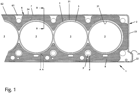
[0025] Figure 1 shows a partial top view of a cylinder head gasket 1 with a
single metallic layer 2. In
this gasket layer, four combustion chamber openings are given, one of them on
the left hand side
being only partially shown. The combustion chamber openings 3 are each
surrounded by a circular
sealing area with a circular bead 5. The dotted lines show only the course of
the peak of the bead. In
the area between the combustion chamber openings 3, the beads 5 combine to a
joint bead section.
CA 02682759 2009-10-01
WO 2008/128788 PCT/EP2008/003330
The sealing areas 4 therefore result in a spectacle-like shape and extend from
the edge 31 of the
combustion chamber openings 3 to the outer feet of the bead, the position of
which is designated by
line 51.
[0026] In the so-called backland of the gasket layer 2 - in the area between
the feet of the beads 51
and the outer gasket edge 23, further through-openings are present in the
shape of screw openings,
water- and oil openings, which are however not identified individually. Some
of these through
openings 3' are surrounded by sealing areas 4' as well, in which an
elastically deformable sealing
element such as a bead or an elastomeric lip (not shown) are present. Apart
from the sealing areas 4,
the gasket also shows a functional area 6, with a half bead 7 which
constitutes a step in the direction of
the outer edge 23 but is not depicted in detail and runs along the outer edge
23 of the gasket layer 2.
The functional area 6 runs strip shaped along the gasket edge 23 between the
inner and outer foot of
the half bead 7. The area is marked by dotted lines 61 and 62. The functional
area does not run
directly at the outer edge 23 of the gasket but at a distance to it. Between
the outer edge 23 and the
outer foot of the bead (dotted line 62) a flat area 24 is situated. This area
24 and the regions in
between the dotted lines 61 do not belong to the functional area 6.
[0027] According to the invention, a structured area 8 is present outside of
the sealing area 4, 4' and
the functional area 6. This structuring is indicated in figure 1 by a
hatching. As can be seen from figure
1, there is no link between the ends of depressions or protrusions,
respectively. As can be seen from
figure 1 as well, the structured area in this embodiment extends at large
scale over the so-called
backland of the gasket layer and covers it essentially completely. This means
that at least 70%,
preferably more than 80% and most preferably more than 90% of the area of the
gasket layer outside
the sealing areas 4, 4' and the functional area 6 have the structuring. The
structuring 8 crosses the
whole thickness of the layer in the respective area from surface 21 to the
backside surface 22. If the
entire extension of the gasket layer is considered, thus without subtraction
of the sealing and functional
areas, at least 50%, preferably at least 60% and most preferably at least 70%
of the surface of the
gasket layer are covered by the structuring in this embodiment.
[0028] The course of the structure from the lower left to the upper right also
clarifies the progress of
the protrusions 9 and the depressions 10 along the area 8. The depressions 9
run as straight extended
grooves, the protrusions 10 as straight extended ribs over the entire
structured area 8 and are only
interrupted by the through-openings and if present by the sealing elements
surrounding them
[0029] Figures 2 and 3 show two different cross sections of the depressions
and protrusions in the
structured area 8 in a sectional view along line A-A in figure 1. In the
embodiment according to figure
CA 02682759 2009-10-01
WO 2008/128788 PCT/EP2008/003330
11
2, both the protrusions 10 and the depressions 9 show an essentially
trapezoidal cross section. The
flanges of the trapezoidal cross section, as is preferred, do not extend
vertical, but at an angle of at
least 10 relative to the vertical direction, thus allowing for a transition
region. The peak areas of the
protrusions 10 are essentially flat. In the embodiment according to figure 3,
the cross sections of the
depressions 9 and the protrusions 10 are rounded. In both embodiments the
linear structure of the
structured area is arranged in such a way that a depression 9 on the upper
side 21 corresponds to a
protrusion 10 on the lower side 22 and vice versa. This results in an
undulating structure. The
structured areas may be manufactured by embossing of the gasket layer 2. This
leads to an increased
effective thickness Dl in the hatched area 8 compared to the original
thickness of the gasket layer 2,
D2. The material thickness as such is only slightly modified.
[0030] Figures 4 and 5 show cross sections of a one-layered metallic flat
gasket on the example of a
cylinder head gasket. The cross sections each show the area between a
combustion chamber opening
3, which is situated at the right hand side of the figure, and the outer edge
23 of the gasket layer,
situated on the left in the figure. The combustion chamber opening 3 is
completely encircled by a
bead 5. The outer edge 23 of the gasket layer is completely encircled by a
half bead 7 at a distance to
the edge and a flat section 24 between the half bead 7 and the edge. The
structured area 8 is situated
between the half bead 7 and the bead 5. It can be designed as shown in figures
2 or 3 and shows
alternating depressions 9 and protrusions 10. The gasket layer 2 has a larger
effective thickness in the
area 8 than in other areas, which is why the structure also acts as a
deformation limiter both for the
bead 5 and for the half bead 7. Due to the large extension of the structuring
8 across the area of the
gasket layer 2 in this embodiment (see also figure 1), distortions of the
elements to be sealed against
each other can effectively be prevented, especially if the height of the
structure is modified over the
extension commensurate to the width of the sealing gap between engine block
and cylinder head in
the respective area.
[00311 The gasket shown in figure 5 possesses more structured areas than the
one from figure 4.
These additional structured areas on the one hand are situated in the area
between the bead 5 and
the edge 31 of the combustion chamber opening 3 and on the other hand replace
the unstructured
section 24 between the half bead 7 and the outer edge 23 of the gasket layer.
[0032] Figures 6 and 7 show two-layered gaskets in a sectional view along line
B - B in figure 1. The
upper gasket layer 2 corresponds to the single gasket layer in figure 4 and
therefore needs no detailed
description. In figure 7, the lower layer 2' is arranged in such a way that it
is a mirror image of layer 2.
In contrast, layer 2' in the example of figure 6 shows no structuring. The
areas in layer 2' adjoining the
structured areas 8 in layer 2 are smooth (indicated by 25).
CA 02682759 2009-10-01
WO 2008/128788 PCT/EP2008/003330
12
[0033] Figure 8 shows a three-layered cylinder head gasket in a sectional view
along line B - B. The
lowest gasket layer 2' corresponds to the lower gasket layer 2' in figure 6.
The upper gasket layer 2 is a
mirror image of the lower gasket layer 2'. A third gasket layer 2" is arranged
between layers 2 and 2'. It
is structured in the areas between the beads 5, 5', and the half beads 7 and
7' in the adjoining layers
but shows no beads of its own. The structured areas 8 extend beyond the
neighboring surface of
gasket layer 2" and constitute an area of increased thickness. In this way,
the structured areas act as
deformation limiter for the beads 5, 5', 7 and 7'.
[0034] Figure 9 depicts a four-layer cylinder head gasket in a partial cross
section along line B - B in
figure 1. The gasket corresponds to a mirror-image combination of two gaskets
according to figure 6.
Such four-layered gaskets allow to even seal extremely wide sealing gaps
between engine block and
cylinder head.
[0035] A further example of a four-layered cylinder head gasket is given in
figure 10. In order to
increase the total thickness of the gasket, two so-called distant layers which
have not structure or
sealing elements on their own are used in this gasket only for the increase of
the total thickness. A first
distant layer 2' is arranged between two gasket layers 2 and 2" which among
themselves are mirror
images. These two gasket layers correspond to layers 2 and 2' in the gasket
according to figure 7. The
second distant layer 2"' is arranged below layer 2".
[0036] Figures 11 to 13 show further sectional views of one-layered cylinder
head gaskets. Figures 11
and 12 are sections of the gasket between two neighboring through openings or
a through opening
and the outer edge of the gasket. Both gasket areas resemble in principle the
section shown in figure 5.
In contrast to the latter, the gasket in figure 11 however shows no sealing
elements such as beads or
half beads so that it is rather used as a gasket layer together with
additional layer(s) than as a one-layer
gasket. The structured areas 8 are separated from each other by flat areas 25
and 25'.
[0037] Instead of a flat area 25' the gasket according to figure 12 shows a
bead. It is for instance
surrounding a through opening which might follow on the right side of the
section of gasket layer 2
depicted.
[0038] Figure 13 shows a sectional view of a gasket according to the invention
in the area of a bolt
opening 3', e.g. a sectional view along line C - C in figure 16. The bolt
opening 3' is surrounded by
structured areas 8. The lower side of the head of the bolt Si, when the bolt
is inserted into the bolt
hole and tightened (not shown), seats solidly on the structured area 8. In
this way, a portion of the
forces is introduced into the structured areas 8. Due to the protrusions and
depressions, the structured
CA 02682759 2009-10-01
WO 2008/128788 PCT/EP2008/003330
13
areas have a higher deformability than the flat gasket layer 2. A targeted
design of the depressions and
protrusions allows a regulation of the forces introduced into the area of the
bolt openings 3'.
[0039] The structured areas 8 are preferably introduced into the gasket layers
through embossment. A
suitable embossing die P is shown schematically in figure 14. It serves here
for the embossment of a
gasket layer 2, which resembles the gasket shown in figure 11. The embossing
die P consists of two
plates P1 and P2, the structured surfaces of which point towards each other
and have a distance H,
with the gasket 1 being placed in between these two forms. The plates P1 and
P2 can be moved from
and towards each other along the guiding pins P5 using the die shoes P3 and P4
and a press.
[0040] For the embossment of the depressions 9 of the structured areas 8 into
a pre-form of the
gasket layer 2, the plates P1 and P2 show protruding areas P6 on their sides
used for embossing with
protrusions and depressions which are complementary to the depressions and
protrusions in the
structured areas 8 in the gasket layer 2. The plates P1 and P2 show clearances
P7 in those regions that
correspond to the areas in the gasket layer which are to be kept free from
structuring so that those
areas are not altered by the embossment. When closing the plates P1 and P2,
the protruding areas P6
of the plates P1 and P2 impress into the gasket layer 2 and produce structured
areas 8. Figure 14
shows the embossing die P after the embossment and after the plates P1 and P2
have been shifted
apart from each other.
[00411 Figures 15 and 16 give further examples of cylinder head gaskets
according to the invention in
top view, respectively. Both gaskets resemble the one shown in figure 1. In
the gasket according to
figure 15, the bolt openings 3' are surrounded by sealing areas 4' with
sealing beads encircling the bolt
openings 3'. The bolt openings 3' with their sealing area 4' are all
surrounded by structured areas 8,
which are extending almost entirely over that area of the gasket layer 2 which
is neither sealing area 4,
4' nor functional area.
[0042] The cylinder head gasket shown in figure 16 distinguishes from the one
in figure 15 on the one
hand by the bolt holes 3' not being surrounded by a bead and therefore by no
sealing area. The
structured area 8 therefore connects almost directly to the outer edges of the
bolt openings 3. On the
other hand, the gasket of figure 15 only shows one cohort of virtual parallel
lines, while figure 16
comprises two cohorts of virtual parallel lines, which intersect at an angle
of about 90 .
[0043] In addition to figures 2 and 3, figure 17 shows exemplary perspective
sections of the surface-
structured areas 8. The protrusions and depressions, respectively, may for
instance show trapezoidal
(see figure 17-a), triangular (see figure 1 7-b) or rounded profiles (see
figure 17-c). As can be seen from
CA 02682759 2009-10-01
WO 2008/128788 PCT/EP2008/003330
14
figure 17-d, rounded forms may be mixed with straight sections. Figure 17-e
demonstrates how two
cohorts of virtual parallel lines intersect. While the lines running from the
lower left corner to the
upper right corner have a high density, only two of the lines intersecting
with them at an angle of
about 90 are shown.
[0044] Figures 18 to 20 show partial top views on further examples of cylinder
head gaskets according
to the invention. While the structured area 8 in figures 18 is limited to the
area close to the shorter end
26 of the gasket edge 23, which considered from the combustion chamber lies
behind the fastening
holes 3', the example of Figure 19 shows additional small areas at the
longitudinal edge of the gasket
in the immediate neighborhood to the holes for the fastening means 3'. In the
example of figure 19,
the virtual straight lines run at an angle of about 45 to the outer edges of
the gasket layer, whereas
they run in parallel to the shorter gasket edge in figure 18. The latter is
also true for the embodiment
shown in figure 20, where the surface structure is arranged like a collar or
corona distant to and
around the combustion chamber openings 3 and completely cover the area of the
fastening means 3',
but not the one of the fluid openings 3". The surface structuring reaches to
the border of the
functional area 6, thus it does not reach beyond the step of the half bead and
does not reach to the
edge of the gasket. The latter was also true for the example of figure 18 but
not for the one of figure 19
where the structuring is completely situated between the outer edge 23 of the
gasket and the half bead
7 of the functional area 6. In all examples, the structuring apart from edge
areas tapering off, e.g.
triangular edge areas, is such that the length of the structured area in the
extension direction is at least
3 times, preferably at least 5 times as large as a period of the structuring
reaching from the top of a
crest to the top of the neighboring crest of the structuring.
[0045] On the example of a manifold gasket, figure 21 demonstrates that the
virtual straight lines may
only intersect in an area where the structuring as such is not present. As can
be seen from the detailed
figures A/B and C/D, the cohort of virtual straight lines that defines the
direction of the structuring 8
around the through openings for fastening means 3' runs essentially orthogonal
to the cohort of virtual
straight lines that defines the direction of the structuring 8 around another
through opening for
fastening means 3'. Outside of the sealing area 4, in the example shown the
structuring 8 is only
present in a limited area around the holes for fastening means 3'.
[0046] Figure 22 demonstrates that the surface structuring may also be used in
combination with
various kinds of sealing or supporting elements, e.g. with a separate bead
ring, which according to the
properties of the material used may be used as sealing element (resilient
material) or as a stopper for a
sealing element in a further gasket layer, the latter not being depicted. The
other two gasket layers
show the structuring in combination with classical stopper elements, namely a
folded-over stopper or a
CA 02682759 2009-10-01
WO 2008/128788 PCT/EP2008/003330
bended flange, which both act as deformation limiters for a bead in a further
layer of the gasket, which
is however not shown.
[0047] Figure 23 shows an embodiment of the metallic flat gasket which
deviates in two points from
the preceding embodiments of the invention. On the one hand, is a multi-layer
gasket with three
gasket layers 2, 2' and 102. The structuring within each layer consists only
of one cohort of virtual
straight lines which run in the same direction for structuring 8 and 108, but
at a different angle for
structuring 8', preferably at a right angle with respect to the other two
structurings. The cross section is
taken at a position where the structure 8' in gasket layer 2' shows a
protrusion 9. Owing to the
alternating orientation of the structures 8, 8' and 108, hollow structures 80
are formed in between the
gasket layers but also between the outer gasket layers 2, 102 and the flanges
of the pipes 90, 91 to be
sealed. These hollow structures 80 improve the insulation behavior of the
gasket 1. On the other hand,
the gasket layer 102 extends over the outer edges of the other gasket layers 2
and 2' with the
extending section 112 being bent out of the plane of the gasket. The shape of
the extending section
112 is such that it works as a deflector and guides cool air into the hollow
structures 80 in between the
gasket layers. Therefore, the embodiment of Figure 23 is preferred for
applications with hot gases.
While it is preferred to use the bent extending sections 112 only in
connection with the hollow
structures 80, the latter can be used without the former since it reduces the
number of contact points
between the gasket layers.
[0048] Figure 24 shows a detail from a region of a gasket layer, in which a
structuring 8 is present.
Elevations 9 and depressions 10 are embossed into this region. The elevations
9 protrude by a height
H beyond the surface of the gasket layer 2. As a result of the embossing, the
thickness of the gasket
layer 2 in the region of the flanks 19 has been reduced relative to the
thickness of the elevations 9 or
depressions 10. The thickness D19 in the flank region is therefore less than
the thickness D9 of the
gasket layer 2 in the region of the elevations or depressions. This reshaping
of the material and
reduction of the material thickness lead to an increase in the rigidity of the
structured region. For
demonstration purpose, the extent of the flank tapering is exaggerated in
Figure 24. It is frequently
between 10 and 25 %, in particular between 13 and 19 %. Figure 24 also
indicates that a period of the
structuring, P, is usually about 2.5 to 3.5 times larger than the original
thickness of the gasket layer, H.
The ratio P/H in general does not exceed 4.