Note: Descriptions are shown in the official language in which they were submitted.
CA 02682865 2009-10-15
231027
A SYSTEM AND METHOD FOR CHANGING THE EFFICIENCY OF A
COMBUSTION TURBINE
BACKGROUND OF THE INVENTION
The present invention relates to the operation of a thermal control system on
a
combustion turbine, and more particularly to an anti-icing system that uses a
heat
source located external to the combustion turbine.
Operators of combustion turbines, including aero-derivatives, seek the maximum
output and efficiency from the machines. This typically occurs when operating
at
baseload. During baseload operation the majority of compressed air from the
compressor section is combusted; and the inlet guide vanes (IGVs) are full
opened,
allowing the compressor to drawn in the maximum amount of air from the ambient
environment.
To generate additional power from an existing combustion turbine, an inlet air
conditioning system is commonly used. The air conditioning system increases
the
airstream density by lowering the temperature of the airstream entering the
compressor section of the combustion turbine. This increases the mass flowrate
of the
airstream entering the compressor, resulting in increased efficiency and power
output
of the combustion turbine. An air conditioning system may have the form of,
for
example, but not limiting of, a chiller system located within an inlet system
of the
combustion turbine.
However, baseload operation or maximum output from the combustion turbine,
though desired by operators, is not always feasible. There may not be a demand
in the
energy market (electrical grid, or the like) for all of the energy generated
at baseload.
Here, the combustion turbine must either be shutdown or operate at a partload,
where
less than the maximum amount of energy is generated. In some energy markets
1
CA 02682865 2009-10-15
231027
partload operation typically occurs during the evening or nighttime hours,
when
power demands generally subside.
Some combustion turbines operate in cold, humid ambient environments. These
environments can allow ice to form within the inlet system and on components
of the
compressor section; which may be harmful to the combustion turbine. Anti-icing
systems are used to prevent or remove this icing. These systems may be a
function of
an inlet bleed heat system (IBH), which re-circulates hot compressor discharge
air to
the inlet system, raising the temperature of the inlet airstream. Furthermore,
anti-icing
systems typically modulate the IGVs to reduce the amount of air entering the
compressor section. During anti-icing operation the power and efficiency of
the
combustion turbine are significantly reduced.
For the foregoing reasons, there is a need for an anti-icing system that does
not
significantly impact the output and efficiency of the combustion turbine. The
system
should incorporate an external heat source to increase the temperature of the
airstream
entering the compressor section. The system should integrate with a pre-
existing air
conditioning system to increate the airstream temperature.
BRIEF DESCRIPTION OF THE INVENTION
In an accordance with embodiment of the present invention, a system for
changing the
efficiency of a combustion turbine (150) operating at partload, the system
comprising:
an inlet system (100) configured for receiving an airstream, the inlet system
(100)
comprising: an inlet bleed heat (IBH) system (125) and an air conditioning
system
(115) configured for adjusting a temperature of the inlet air; wherein the
airstream
enters the air conditioning system (115) at a first temperature and exits the
air
conditioning system (115) at a second temperature; a combustion turbine (150)
comprising a compressor section (155), wherein the compressor section (155)
comprises an inlet guide vane (IGV) system, and wherein the compressor section
(155) receives the airstream from the inlet system (100); and a heat source
(140)
located to the combustion turbine (150) and integrated with the air
conditioning
system (115); wherein the heat source increases the temperature of airstream.
2
CA 02682865 2009-10-15
231027
BRIEF DESCRIPTION OF THE DRAWINGS
Figure 1 is a schematic illustrating an example of a system for increasing the
efficiency of a combustion turbine in accordance with a first embodiment of
the
present invention.
Figure 2 is a chart illustrating a typical inlet bleed heat map used in anti-
icing
operations.
Figure 3 is a chart illustrating the benefits of an embodiment of the present
invention.
Figure 4 is a schematic illustrating an example of a system for increasing the
efficiency of a combustion turbine in accordance with a second embodiment of
the
present invention.
DETAILED DESCRIPTION OF THE INVENTION
The following detailed description of preferred embodiments refers to the
accompanying drawings, which illustrate specific embodiments of the invention.
Other embodiments having different structures and operations do not depart
from the
scope of the present invention.
Certain terminology may be used herein for the convenience of the reader only
and is
not to be taken as a limitation on the scope of the invention. For example,
words such
as "upper", "lower", "left", "right", "front", "rear", "top", "bottom",
"horizontal",
"vertical", "upstream", "downstream", "fore", "aft", and the like; merely
describe the
configuration shown in the Figures. Indeed, the element or elements of an
embodiment of the present invention may be oriented in any direction and the
terminology, therefore, should be understood as encompassing such variations
unless
specified otherwise.
The present invention may be applied to a wide variety of combustion turbines
including, but not limiting of, aero-derivative turbines, and the like. An
embodiment
of the present invention takes the form of an application and process that
incorporates
an external heat source to increase the temperature of the airstream entering
a
3
CA 02682865 2016-04-20
231027
compressor section of a combustion turbine. An embodiment of the present
invention
may perform an anti-icing operation that may not require an IBH system to
operate.
An embodiment of the present invention may perform an anti-icing operation
that
may allow for the IGV angle to remain nearly constant. An embodiment of the
present invention may increase the output and efficiency of a combustion
turbine
operating at partload by delaying IBH operation and delaying the closing IGVs.
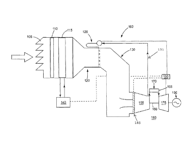
Referring now to the Figures, where the various numbers represent like
elements
throughout the several views, Figure 1 is a schematic illustrating an example
of a
system for increasing the efficiency of a combustion turbine 150 in accordance
with
an embodiment of the present invention. Figure 1 illustrates a site comprising
an inlet
system 100; integrated with a combustion turbine 150; and a turbine control
system
190.
The inlet system 100 channels the airstream (represented by the arrow pointed
towards the inlet system 100) ingested by the compressor section 155. The
airstream
may derive directly or indirectly from the environment in which the combustion
turbine 150 operates. Initially, the airstream flows around a weather hood
105, which
may prevent weather elements, such as rain, snow, etc, from entering the
compressor
section 155. The airstream may then flow through an inlet filter house 110;
which
generally removes foreign objects and debris from the airstream. Next, the
airstream
may pass through an air conditioning system 115. Next, the airstream may pass
through a transition piece 120 and an inlet duct 130; these components may
adjust the
velocity and pressure of the airstream, prior to entering the compressor
section 155.
The airstream may also flow through an IBH system 125. When operating, the IBH
system 125 increases the temperature of the airstream by recirculating a
portion of the
compressor discharge along a recirculation line 135 and air through an IBH
heat
exchanger, or the like.
The inlet system 100 is generally integrated with the combustion turbine 150;
which
comprises a compressor section 155, which may include an IGV system 185, a
combustion system 165, and a turbine section 175. The airstream generally
exits the
inlet system 100 and enters the compressor section 155, is compressed and then
discharged to a combustion system 165, where a fuel 170, such as natural gas,
is
4
CA 02682865 2009-10-15
231027
burned to provide high-energy combustion gases which drives the turbine
section 175.
In the turbine section 175, the energy of the hot gases is converted into
work, some of
which is used to drive the compressor section 155 through the shaft 160, with
the
remainder available for useful work to drive a load such as the generator 180.
A turbine control system 190 generally controls the operation of the
combustion
turbine 150 and the inlet system 100 components. The turbine control system
190
may receive operating data on the ambient conditions of the airstream. The
operating
data may be used to schedule the operation of the IBH system 125.
For example, but not limiting of, the turbine control system 190 may start the
IBH
system 125 if the ambient temperature is below approximately 40 Degrees
Fahrenheit
and if the airstream temperature is within approximately 10 Degrees Fahrenheit
of the
airstream dew point temperature. Here, the turbine control system 190 may
employ a
closed loop control scheme to maintain the airstream temperature approximately
10
Degrees Fahrenheit above the dew point to prevent condensation, which could
form
ice on surfaces below approximately 32 Degrees Fahrenheit. As illustrated in
Figures
2 and 3, anti-icing operations employing the IBH system 125 may significantly
impact
the output and efficiency of the combustion turbine 150.
Figure 2 is a chart 200 illustrating a typical inlet bleed heat map that may
be used by
the turbine control system 190 while controlling the IBH system 125 for an
anti-icing
operation. Specifically, Figure 2 illustrates a plurality of data when the
combustion
turbine 150 may be operating at partload when the airstream temperature is
approximately 20 Degrees Fahrenheit. In Figure 2, the x-axis 205 represents an
IGV
185 angle, the first y-axis 210 represents an airstream temperature, and the
second y-
axis represents the output of the generator 180. Figure 2 illustrates the
effect on the
output of the combustion turbine 150 that an anti-icing operation may have
when
employing an IBH system 125.
Data series 225 plots the IGV 185 angle on the x-axis 205 versus an airstream
temperature on the first y-axis 210. Here, the chart 200 illustrates that
before anti-
icing operations, the airstream was approximately 20 Degrees Fahrenheit. Then,
when the IGVs 185 are reduced to approximately 65 degrees, the airstream
CA 02682865 2009-10-15
231027
temperature begins to increase, which reflects the effect of the anti-icing
operation.
This may be considered reference point A (hereinafter "REF_A") and illustrated
as
'A' on Figure 2. Furthermore, when the IGV 185 angle is reduced to
approximately
44 degrees, the airstream temperature increases to approximately 50 Degrees
Fahrenheit. This may be considered reference point B (hereinafter "REF_B") and
illustrated as '13' on Figure 2.
Data series 220 plots the IGV 185 angle on the x-axis 205 versus the output of
the
generator 180 on the second y-axis 215. At REF_A the decrease in output
associated
with operating the IBH system 125. Specifically, between an IGV 185 angle of
65
and 60 degrees, the output decreases as the IGV 185 angle decreases and as the
airstream temperature increases. Furthermore, REF_B illustrates a significant
decrease in output by the combustion turbine 150. At REF_A the output is
approximately 150 megawatts, and at REF_B the output is approximately 60
megawatts. This decrease in output also translates to a decrease in the
efficiency of
the combustion turbine 150 while operating at partload.
Referring again to Figure 1, an embodiment of the present invention may
provide an
external heat source 140 configured to increase the temperature of the
airstream
flowing within the inlet system 100. As discussed, the inlet system 100 may
comprise
an air conditioning system 115, having the form of a chilling system or the
like.
Typically, the air conditioning system 115 may be used to decrease the
temperature of
the airstream when the combustion turbine 150 operates in the ambient
conditions
above a rated temperature range. Typically, the air conditioning system 115
does not
operate when ambient condition allows for icing to occur within the inlet
system 100
or the combustion section 155.
An embodiment of the present invention integrates an external heat source 140
with
the air conditioning system 115 to heat the airstream when the combustion
turbine 150
operates in an ambient condition that allows for icing to occur. This may
reduce the
need to operate the IBH system 125, thereby increasing the efficiency and
output of
the combustion turbine 150.
6
CA 02682865 2009-10-15
231027
The external heat source 140 may be of any form that does not directly receive
heat
from the combustion turbine 150. For example, but not limiting of, the
external heat
source 140 may have the form of at least one of: a heat recovery steam
generator; a
boiler; an engine, a condensor; a power plant component, a solar energy
source,
geothermal energy source, a fuel cell/chemical reaction, and combinations
thereof.
In use, the turbine control system 190 may be integrated with the external
heat source
140 to control the heating of the airstream via the air conditioning system
115. An
embodiment of the present invention may perform the following steps to perform
an
anti-icing process on the inlet system 100 and the combustion turbine 150.
Determine
when the combustion turbine 150 is operating at partload. Determine whether a
temperature of the airstream is below a temperature range; and then determine
whether to operate the air conditioning system 115 to raise the temperature of
the
airstream above the temperature range, if required. The turbine control system
190
may also provide a bias that delays the modulation or closing of the IGV
system 185
when the air conditioning system 115 operates. The turbine control system 190
may
also provide a bias that delays the operation of the IBH system 125 when the
air
conditioning system 115 operates.
The turbine control system 190 may determine an efficiency of the combustion
turbine 150 while control the external heat source 140. This may occur while
the
turbine control system 190 receives data on: an ambient condition; an output
of the
heat source. The ambient condition data may include at least one of: an
ambient
temperature, an ambient pressure, an ambient humidity, or combinations thereof
As discussed, an embodiment of the present invention may increase the
efficiency of a
combustion turbine 150 operating at partload. An embodiment of the present
invention may delay or avoid the use of the IBH system 125 and also delay or
avoid
closing the IGVs 185 of the compressor section 155. Figure 3 is a chart 300
illustrating the benefits of an embodiment of the present invention.
Specifically,
Figure 3 illustrates a plurality of data when the combustion turbine 150 may
be
operating at partload when the airstream temperature is approximately 20
Degrees
Fahrenheit. In Figure 3, the x-axis 305 represents an IGV 185 angle, the first
y-axis
7
CA 02682865 2009-10-15
231027
310 represents an airstream temperature, and a normalized power output of the
combustion turbine 150, and the second y-axis 315 represents the heat-rate of
the
combustion turbine 150. Figure 3 includes data series 320, which represents a
first
generator output, which is similar to data series 220 illustrated in Figure 2.
Furthermore, the reference points A and B of Figure 2 are similarly positioned
in
Figure 3. Figure 3 also includes the data series 225 of Figure 2, which
illustrates the
airstream temperature. Figure 3 also includes data series 340, which
represents the
heat-rate of the combustion turbine 150.
Figure 3 also illustrates improvements to the output and the heat-rate of the
combustion turbine 150 when an embodiment of the present invention is
employed.
Data series 330 may represent a first heat-rate, which is of the combustion
turbine 150
operating in a 20 Deg. F airstream environment. Data series 330 illustrates
the effect
of operating an anti-icing system using an IBH system 125.
At REF _A the effects of the anti-icing operation using the IBH system 125
starts to
become evident. Here, data series 330 illustrates the first heat-rate to be
approximately 9.25 BTU/KWH; data series 320 illustrates the normalized power
output to be approximately 85%, and data series 225 illustrates the airstream
temperature to be approximately 20 Deg. F.
At REF _B the severe operational effects of the anti-icing operation are
evident. Here,
data series 330 illustrates the first heat-rate to be approximately 14.15
BTU/KWH;
data series 320 illustrates the normalized power output to be approximately
31%; and
data series 225 illustrates the airstream temperature to be approximately 50
Deg. F.
Figure 3, also illustrates the benefits to combustion turbine 150 when an
embodiment
of the present invention provides an external heating source 140 for an anti-
icing
operation. These benefits may include an increase in power output, represented
by
data series 325; and a decrease in the heat-rate, represented by data series
335.
Figure 3 may be used to compare the heat-rate and output of the combustion
turbine
150 undergoing anti-icing operations. The anti-icing operations are
illustrated with the
IBH system 125 used; and when the external energy source 140 is used, as
previously
8
CA 02682865 2009-10-15
231027
described. The first heat-rate may be considered the heat-rate associated with
using
the IBH system 125 for anti-icing and is represented by data series 330. The
second
heat-rate may be considered the heat-rate when the IBH system 125 is not used
for
anti-icing, as previously described, and is represented by data series 335.
The first
generator output may be considered the output associated with using the IBH
system
125 for anti-icing and is represented by data series 320. The second generator
output
may be considered the heat-rate when the IBH system 125 is not used for anti-
icing,
as previously described, and is represented by data series 325.
For example, but not limiting of, at reference point B' (hereinafter "REF_B'
") and
illustrated as "B' "on Figure 3, the comparison operating data shown in Table
1 is
illustrated.
TABLE 1
Approximate IGV Approximate Heat Approximate
Angle Rate Normalized Power
Output
With IBH 51 48% 11500 btu/kwn
Without IBH 51 56% 9661 btu/kwh
Figure 4 is a schematic illustrating an example of a system for increasing the
efficiency of a combustion turbine 150 in accordance with a second embodiment
of
the present invention. Figure 4, illustrates the combustion turbine 150
adapted to
operate in a combined cycle mode. Here, waste heat exiting the turbine section
175
may flow to a heat recovery steam generator (HRSG) 420, or other the like. The
HRSG 420 may create steam from the waste heat. The steam may flow to a steam
turbine 425, which may transfer some of the energy in the steam into
electricity
generated by a second generator 430. This process may cause the steam to
condense
and the condensate may flow to a condensor 435.
The condensate may become the external heat source 140 integrated with the air
conditioning system 115 to prevent anti-icing. In an embodiment of the present
9
CA 02682865 2016-04-20
231027
invention the condensate may flow through a chilling system of the air
conditioning
system 115. Here, at least one valve 405 may regulate the flow of the
concentrate
entering the air conditioning system 115. The condensate may then flow through
the
air conditioning system 115, heating the airstream flowing over the air
conditioning
system 115. The airstream temperature, which may be determined by a
temperature
element 410 and a thermocouple 415, may be used by the turbine control system
190
to determine the position of the valve 405. The condensate may then return to
the
condensor 435 and return to the HRSG 420, after flowing through the air
conditioning
system 115.
The terminology used herein is for the purpose of describing particular
embodiments
only and is not intended to be limiting of the invention. As used herein, the
singular
forms "a", "an" and "the" are intended to include the plural forms as well,
unless the
context clearly indicates otherwise. It will be further understood that the
terms
"comprises" and/or "comprising," when used in this specification, specify the
presence of stated features, integers, steps, operations, elements, and/or
components,
but do not preclude the presence or addition of one or more other features,
integers,
steps, operations, elements, components, and/or groups thereof.
Although specific embodiments have been illustrated and described herein, it
should
be appreciated that any arrangement, which is calculated to achieve the same
purpose,
may be substituted for the specific embodiments shown and that the invention
has
other applications in other environments. This application is intended to
cover any
adaptations or variations of the present invention. The following claims are
in no way
intended to limit the scope of the invention to the specific embodiments
described
herein.