Note: Descriptions are shown in the official language in which they were submitted.
CA 02682961 2014-09-09
24280-115
- 1 -
METHODAND DEVICEFORCONTROLLINGATLEASTONEDRILLING PARAMETER
FORROCKDRILLING
Technical field
The present invention relates to a method and a device
for controlling drill parameters when drilling in rock.
Background of the invention
Rock drilling is often carried out by percussion
drilling, where a percussion piston, which is often
= operated hydraulically, is used to create a shock wave
with the aid of an impact force that is generated by
hydraulic pressure (percussion pressure), the shock
wave being transmitted to the drill bit and _hence to
the rock through the drill steel (drill string). On
contact with the rock, pins made of a hard alloy of the
drill bit contacting the rock is pushed into the rock,
generating a strong enough force to fragment the rock.
In rock drilling of this kind, it is important that the
start of the drilling is performed correctly and that
drilling is done with care during normal drilling (i.e.
drilling with high impact force) in order to ensure
that the drilling takes place in a manner that does not
damage the drilling machine/drilling rig.
It applies in general, and especially in the case of
drilling under difficult rock conditions and with a
strong impact force, that the drill bit should have as
good a contact with the rock as possible. A common way
of achieving this is to use a piston which works
against the drill steel (drill string) and which is
usually in the form of a damping piston, which is also
used to damp reflexes from the impact of the shock
waves against the rock. During drilling, the damping
piston is pressed against the drill steel, and the
CA 02682961 2009-09-30
WO 2008/127172
PCT/SE2008/000256
- 2 -
drill steel is thus pressed against the rock, by
pressurization of a pressure chamber working against
the damping piston. The damping piston is also usually
arranged such that, if the damping piston advances too
far, i.e. the area in front of the drill steel is soft
enough for the impact of the percussion piston to cause
the drill steel, and thus the damping piston, to move
forwards and past a normal position, an outlet for said
pressure chamber is completely or partially opened,
resulting in a pressure decrease in the pressure
chamber. By detecting this decrease in pressure, the
status of the contact with the rock can be determined,
and suitable measures can thus be taken.
For example, the percussion pressure can be increased
to a normal drilling level when the damping pressure
' exceeds a defined pressure level, which, for example,
can be a pressure level that has been determined as
being desirable during normal drilling. Moreover, the
percussion pressure can be arranged to be kept at the
normal drilling level as long as the damping pressure
does not fall below a low-pressure level, which, for
example, can be a level that involves lost or poor
contact with the rock. If the damping pressure falls
below this level, the percussion pressure can be
decreased to the start-up drilling level or can be
completely shut off. However, this type of control has
a number of disadvantages.
For example, there is a considerable risk of idle
percussion, i.e. percussion where most of the shock
wave is reflected in the drill bit instead of the rock,
which leads to a large amount of damaging energy being
returned to the drilling machine.
There is therefore a need for an improved method and
device for controlling drill parameters, specifically a
method and device that at least partially alleviate the
problems of the prior art.
ak 02682961 2014-09-09
24280-115
- 3 -
Summary of the invention
Some embodiments of the present invention may provide a method
for controlling at least one drill parameter in order to solve
a problem mentioned above.
Some embodiments of the present invention may provide a device
for controlling at least one drill parameter in order to solve
a problem mentioned above.
According to one embodiment of the present invention, there is
provided a method for controlling at least one drill parameter
when drilling in rock with a drilling machine. During the
drilling, an impulse-generating device, using an impact means,
induce shock waves in a tool working against the rock, whereby
a pressure level for a shock-wave-generating pressure is
controlled during the drilling, and where said drilling machine
includes a damping chamber that can be pressurized. The contact
of the drilling machine against the rock is at least partially
affected by the prevailing pressure in said damping chamber.
The method includes the step in which, when the pressure in
said damping chamber exceeds a first level and is below a
second level, the percussion pressure is controlled as a
function of the pressure in said damping chamber.
This has the advantage that, by controlling the percussion
pressure as a function of the pressure in a damping chamber, it
may be possible to ensure in every situation that a correct
percussion pressure is used in relation to the damping
pressure. This in turn means
CA 02682961 2014-09-09
24280-115
- 4 -
that damaging reflexes may be avoided both during
start-up drilling and during normal drilling.
In said control, the percussion pressure can, for
example, be controlled between a first level, which
substantially corresponds to a start-up drilling level,
and a second level, which substantially corresponds to
a normal drilling level.
The first level can, for example, substantially
correspond to a level at which the percussion pressure
is substantially shut off.
Said function can, for example, be one or a combination
of several of the following: proportional to the
damping pressure, inversely proportional to the damping
pressure, exponential to the damping pressure,
logarithmic to the damping pressure, a defined
relationship to the damping pressure.
The control can, for example, be obtained with the aid
of a mathematical relation between damping pressure and
percussion pressure and/or by reference to a table
containing a relationship between damping pressure and
percussion pressure.
The method can further include the step in which, when
the pressure in said damping chamber exceeds said
second level, the percussion pressure is controlled in
such a way that it is maintained substantially at a
pressure corresponding to the percussion pressure for
said second level.
The method can further include the step in which, when
the pressure in said pressure chamber falls below said
first level, the percussion pressure is controlled in
such a way that it is maintained substantially at a
pressure corresponding to the percussion pressure for
said first level.
CA 02682961 2014-09-09
24280-115
- 5 -
Said pressure in said damping chamber can be determined
by determining a parameter value representing a mean
value of the damping pressure in the damping chamber.
The parameter value representing a mean value of the
damping pressure in the damping chamber can, for
example, be determined with the aid of the pressure in
a pressure feed line for said damping chamber.
The damping pressure can, for example, be determined
continuously and/or at certain intervals by sensoring,
monitoring, measurement or calculation.
The mean value can, for example, be determined based on
a plurality of impulse cycles.
The method can further include the step in which, when
said damping pressure exceeds a third level higher than
said second level, the percussion pressure is
controlled as a function of said damping pressure, with
said percussion pressure exceeding said second
percussion pressure level.
The method can further include the step of controlling
the percussion pressure in such a way that the time for
an increase of said percussion pressure from the first
level to the second level exceeds a threshold value.
The feed rate of the drilling machine can also be used
in controlling the percussion pressure. In this case,
the dependency of the percussion pressure on the
damping pressure can be made to depend partly on the
feed rate.
ak 02682961 2014-09-09
24280-115
- 5a -
According to another embodiment of the present invention, there
is provided a device for controlling at least one drill
parameter when drilling in rock with a drilling machine, where,
during drilling, an impulse-generating device, by means of an
impact means induce shock waves in a tool working against the
rock, wherein a pressure level for a shock-wave-generating
pressure is controlled during the drilling, said drilling
machine including a damping chamber that can be pressurized,
and control of contact of the drilling machine against the
rock being affected at least partially by pressure prevailing
in said damping chamber; wherein the device includes means for,
when the pressure in said damping chamber exceeds a first level
and is below a second level, controlling percussion pressure as
a function of the pressure in said damping chamber.
According to another embodiment of the present invention, there
is provided a rock-drilling rig comprising the device above.
CA 02682961 2014-09-09
24280-115
- 6 -
Other advantages are obtained by various embodiments of the
invention and will become clear from the following
detailed description.
Brief description of the drawings
Fig. 1 shows an example of a drilling rig in which the
present invention can be used.
Fig. 2 shows in greater detail the drilling machine
arranged on the drilling rig shown in Fig. 1.
Fig. 3 shows an example of a control of the percussion
pressure according to the prior art.
Fig. 4 shows an example of a control of the percussion
pressure according to one illustrative embodiment of
the present invention.
Fig. 5 shows an example of a control of the percussion
pressure according to a second illustrative embodiment
of the present invention.
Detailed description of preferred embodiments
The present invention will now be explained by way of
example with reference to a rock-drilling rig of the
type shown in Fig. 1. Fig. 1 shows a rock-drilling rig
10 for tunnelling, for ore mining, or for installing
rock reinforcement bolts in the case of, for example,
tunnelling or mining. The drilling rig 10 comprises a
boom 11, one end ha of which being articulately
connected to a carrier 12, such as a vehicle, via one
or more joints, while the other end lib has a feed beam
13 that supports an impulse-generating device in the
form of a drilling machine 14. The drilling machine 14
is displaceable along the feed beam 13 and generates
shock waves that are conveyed to the rock 17 via a
drill string 15 and a drill bit 18. The rig 10 also
CA 02682961 2009-09-30
WO 2008/127172
PCT/SE2008/000256
- 7 -
comprises a control unit 16 which can be used to
control drill parameters in accordance with the present
invention, and in the manner described below. The
control unit 16 can be used to monitor the position,
direction, drilled distance, etc., with regard to the
drilling machine and carrier. The control unit 16 can
also be used to control the movement of the rig 10,
although a separate control unit can of course also be
used for this purpose.
Fig. 2 shows the drilling machine 14 in more detail.
The drilling machine comprises an adapter 31, one end
of which is provided with means 30, for example screw
threads, for connection to a drill string component
(not shown) in said drill string 15. The drilling
machine also comprises a percussion piston 32 which, by
impacting against the adapter 31, transmits percussion
pulses to the drill string (drill steel) and onwards
from there to the rock. The drill string is advanced to
the rock via a sleeve 33 with the aid of a damping
piston 34, which is arranged in a damping system, which
system is also used for damping the percussion pulses
that are reflected back from the rock, in a manner that
will be explained below. During operation, a force
determined by a hydraulic pressure in a first damping
chamber 37 is transmitted to the adapter 31 via damping
piston 34 and sleeve 33, where said force is used to
ensure that the drill bit is kept pressed against the
rock at all times. The damping piston is also arranged
in such a way that, when it is displaced in the
drilling direction relative to a normal position A, for
example to a position B, which can occur for example
when the drill bit reaches a cavity, or when a harder
type of rock merges into a looser type of rock, in
which case the impact of the percussion piston "pushes
away" the drill string, an outlet 39 is completely or
partially freed and creates a decrease in pressure in
the first damping chamber 37. In addition to a decrease
in pressure being obtained by the outlet 39 being
CA 02682961 2009-09-30
WO 2008/127172
PCT/SE2008/000256
- 8 -
freed, it is also the case that, when the damping
piston moves forwards, a degree of leakage occurs
between damping piston 34 and housing 40 and affects
the pressure in the first damping chamber 37, and, on
the whole, the leakage can be such that, at least in an
area around the position A, a substantially linear
pressure decrease is obtained when the damping piston
moves forwards in the drilling direction so that, when
the outlet 39 is completely freed, a pressure relief is
obtained or a predetermined lowest pressure level, for
example level D1 according to Fig. 3 below. By
measuring the pressure in the first damping chamber 37
regularly, continuously or at certain intervals (the
pressure in the first damping chamber can alternatively
be represented by a pressure that is measured/
determined in or at a pressure feed line to said first
damping chamber 37), the contact of the drill bit with
the rock can be determined, and, since a substantially
linear pressure decrease can be obtained, it is also
possible to determine the position of the damping
piston relative to the normal position A, at least
until the outlet 39 has been completely freed.
In addition to said function of pressing the drill
string against the rock, the damping piston also has a
damping function. When an impact gives rise to reflexes
from the rock, these are damped by means of the damping
piston 34 being pressed into a second damping chamber
38, whereupon fluid in the second damping chamber 38 is
pressed into the first damping chamber 37 through a
small slit, formed between the damping piston 34 and
the chamber wall 35, when the damping piston 34 is
pressed into the second damping chamber 38. This
results in a braking pressure increase in the second
damping chamber 38.
In the prior art, the pressure in said damping chamber
37, or in a feed line to the damping chamber 37, is
used to obtain certain control over the percussion
CA 02682961 2009-09-30
WO 2008/127172
PCT/SE2008/000256
- 9 -
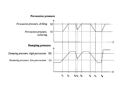
pressure of the drilling machine. Fig. 3 shows an
example of such control. The known method involves
monitoring whether the damping pressure lies at a first
level D1, which represents a level where the damping
pressure is considered to be low, or a second level D2,
which is a level where the damping pressure is
considered to be sufficient to allow drilling to be
safely performed at full force.
At the start of drilling, the percussion pressure is
held at a collaring (start-up drilling) level S1 as
long as the damping pressure is below the higher level
D2. When the damping pressure at a time tl exceeds the
pressure level D2, the percussion pressure is increased
to normal drilling pressure S2, where the percussion
pressure is then held as long as the damping pressure
ddes not fall below the lower pressure level Dl. If, at
a later time t3, the damping pressure falls below the
pressure level D1, the percussion pressure is
decreased, as shown, to the start-up drilling level.
Alternatively, the percussion pressure can be arranged
to be completely shut off if the damping pressure falls
below the pressure level Dl. However, the control
system shown in Fig. 3 has a number of disadvantages.
For example, as is shown, the percussion device can
continue impacting at high force despite the fact that
contact with the rock is in the process of being lost
or is poor, i.e. the damping pressure is below the
level D2, for example between the times t2 and t3 in
Fig. 3. This means that there is a high risk of idle
percussion, especially when the percussion pressure is
high and the damping pressure is near the pressure
level Dl.
The system shown in Fig. 3 also has another
disadvantage. There is a risk of the system self-
oscillating in the event of a sudden drop in damping
pressure to pressure level D1, and the percussion
CA 02682961 2015-04-27
24280-115
- 10 -
pressure thus being rapidly decreased to the start-up drilling
pressure or being completely shut off. This sudden drop in
percussion pressure can in turn lead to an increase in the
damping pressure, whereupon the percussion pressure is again
allowed to increase to normal drilling pressure, and the
damping pressure can fall again, and so on.
The present invention may at least alleviate the disadvantages
of the current systems and will now be described in more detail
with reference to Fig. 4. The basic principle of the present
invention involves controlling the percussion pressure as a
function of the damping pressure, when the damping pressure is,
for example, between the damping pressure levels D1 and D2
which are shown in Fig. 3, and which are also indicated in
Fig. 4. D1 can be a level at which the percussion pressure
should be reduced to the start-up drilling level in order to
ensure that the equipment is not damaged, while D2 can be a
pressure at which contact with the rock is considered to be
good and a high percussion pressure can therefore be accepted.
As can be seen in the figure, the percussion pressure, exactly
as in the prior art, is maintained at a start-up drilling level
as long as the damping pressure does not exceed the level Dl.
In contrast to the prior art, however, an increase in the
percussion pressure begins at tl as soon as the damping
pressure level exceeds the level Dl. In this example, the
percussion pressure is controlled proportionally to the damping
pressure, i.e. if the damping pressure increase is linear, then
the percussion pressure increase is also linear. When the
damping pressure at t2 then reaches the higher level D2, the
percussion pressure is maintained at normal drilling level S2
ak 02682961 2015-04-27
24280-115
- 11 -
as long as the damping pressure does not fall below the
pressure level D2. When the damping pressure temporarily falls
below the level D2 between t3 and t5, the percussion pressure
follows the damping pressure proportionally, as can be seen in
Fig. 4, and at t5 it again assumes the normal drilling
pressure, until the damping pressure again falls below the
pressure level D2 at t6, whereupon the percussion pressure
again falls proportionally to the damping pressure. If the
damping pressure, for example as at t7, is below the pressure
level D1, the percussion pressure is decreased to the start-up
drilling level, as has been shown and described above.
Alternatively, the percussion pressure can be arranged to be
decreased to another suitable level or to be completely shut
off when the damping pressure falls below the pressure level
Dl.
Figure 4 shows a further feature according to one exemplary
embodiment of the present invention. For the purpose of
relieving the stresses on the components and of reducing the
risk of pressure spikes in the hydraulic system, the percussion
pressure can be arranged such that it does not increase more
quickly than at a defined speed, regardless of how quickly the
damping pressure increases, i.e. the percussion pressure
increase is controlled in such a way that the percussion
pressure increase per unit of time is kept below a threshold
value. This is illustrated at t8 where the damping pressure
quickly increases to the level for normal drilling, but where
the percussion pressure is not allowed to increase as quickly.
ak 026E12961 2015-04-27
P
24280-115
- ha -
The present invention affords a number of advantages. For
example, the useful life of the drill bits, drill steel (drill
string) and shank adapter may be increased. This advantage may
be obtained by virtue of the harmful reflexes being reduced,
since the percussion pressure is already lowered when the
damping pressure begins to indicate that the drill bit has
poor/worsening contact with the rock. Another advantage of the
present invention is that a considerably more sensitive system
may be obtained, which may reduce the risk of the self-
oscillation mentioned above.
CA 02682961 2009-09-30
WO 2008/127172
PCT/SE2008/000256
- 12 -
Fig. 5 shows another embodiment of the present
invention. In addition to the levels D1 and D2 and Si
and S2, there is now a further level S3 for the
percussion pressure, this level representing a
percussion pressure that is higher than the normal
drilling pressure S2. There is also a further level D3
for the damping pressure, this level being slightly
above the level D2. When the damping pressure exceeds
D3, the percussion pressure can be allowed to increase
up to the level S3. In this case for example, as is
shown in the figure, the abovementioned control can be
used when the damping pressure exceeds D3. As long as
the damping pressure lies between D2 and D3, the
percussion pressure is maintained at the level S2.
Allowing the percussion pressure to exceed the normal
drilling pressure has the advantage of facilitatin/
permitting drilling in cases where, for example, layers
of considerably harder rock lie interspersed in the
drilled rock. In such situations, it can happen that
the percussion pressure S2 in normal drilling is not
sufficient to fragment the hard rock. By increasing the
percussion pressure in such a situation to a level
exceeding the normal pressure, the energy of the
emitted shock waves is increased, which means that
sections of harder rock can be forced open in this way,
after which the percussion pressure can return to
normal drilling level when the harder part of the rock
has been forced open.
The present invention has been illustrated above in the
case of linear control. However, the percussion
pressure can of course be controlled also according to
any function of the damping pressure. For example, the
percussion pressure can be arranged to increase
exponentially or logarithmically to the damping
pressure. It is advantageous to use a well-known
mathematical function that is easy to program in, e.g.
into the control unit 16, and which is used for the
CA 02682961 2009-09-30
WO 2008/127172
PCT/SE2008/000256
- 13 -
control. Alternatively, the function can be a table
function, i.e. the percussion pressure corresponding to
each damping pressure is looked up in a table.
Moreover, proportionality constants and exponents (and
also factors checked in a table) can be determined at
least partially based on the feed rate of the drilling
machine, i.e. if the feed rate is high, the
proportionality constant/exponent can be set lower,
such that the percussion pressure increases more slowly
compared with the case when the feed speed is low.
In an alternative embodiment, the percussion pressure
is increased in steps, where a certain increase (or
decrease) in the damping pressure results in a step up
(or down). However, each step is small in relation to
the total difference between the first level (Si) and
the second level (S2).
As regards the damping pressure in the damping chamber
37, this can be determined as mentioned above, for
example by measurement/sensoring by means of a pressure
sensor arranged in or near the damping chamber. The
damping pressure is determined sufficiently often, for
example continuously or at regular intervals, to be
able to obtain the variation of the damping pressure at
the stroke of the percussion tool, i.e. such that the
pressure increase pulses that occur upon reflections
from the rock can be detected, after which a mean value
of the damping pressure during a percussion cycle can
be determined. For example, the pressure sensor can be
designed such that it comprises means for calculating
said mean value and then, at each percussion cycle, for
emitting a representation of the mean value. The
pressure sensor can alternatively be designed to emit
signals continuously or at certain intervals (depending
on the percussion frequency of the drilling machine; a
drilling machine operating with a percussion frequency
of several hundreds of hertz, or even in the kHz range,
requires considerably closer intervals compared with a
CA 02682961 2015-04-27
24280-115
- 14 -
drilling machine that operates with a percussion frequency of the
order of 30-50Hz), which signals are then used by an external
element to determine a mean value of the damping pressure for a
percussion cycle. Instead of determining the mean value for one
percussion cycle, it is possible to determine the mean value for a
plurality of percussion cycles. Instead of measuring the damping
pressure in a damping chamber, it is possible, for example, to
measure the pressure on the feed line to the damping chamber. This
has the advantage that the pressure measurement can take place on
the carrier, for example, with reduced routing of cables as a
result.
As has been shown above, the present invention can be used both in
start-up drilling and normal drilling. The invention may be
particularly advantageous in conditions where the rock contains
numerous fissures and/or the hardness of the rock varies greatly,
such that the drill steel occasionally loses contact with the rock
ahead, in which case the risk of harmful reflexes can be reduced.
Nor does the control have to take place throughout the interval
between start-up drilling level (Si) and normal drilling level
(S2), and instead it can be arranged to be carried out only in part
of the interval, for example in half this interval, or in that part
of the interval where there is greatest risk of contact with the
rock being lost.
Furthermore, the present invention has been described in connection
with a percussion drilling machine that comprises a percussion
piston, where the energy of the percussion pulse in principle
consists of the kinetic energy of the percussion piston, which
energy is transmitted to the drill steel. However, the present
invention can also be used with other types of pulse-generating
devices, for example devices in which the
CA 02682961 2009-09-30
WO 2008/127172
PCT/SE2008/000256
- 15 -
shock-wave energy is instead generated as pressure
pulses that are transmitted to the drill string from an
energy storage through a impact means that executes
only a very small movement. In these types of impulse-
generating devices too, a damping pressure can be
measured in a damping chamber, which can in fact be any
chamber, as long as the desired damping function is
achieved.
As will be readily appreciated, although it will still
be mentioned here for the sake of clarity, the
expression "control of a pressure as a function of
another pressure", as used according to the present
invention, does not include the type of control in
which the percussion pressure is suddenly reduced from
the normal drilling pressure to, for example, the
start-up drilling pressure as soon as the damping
pressure passes a threshold value.