Note: Descriptions are shown in the official language in which they were submitted.
CA 02682992 2009-10-05
WO 2008/134017 PCT/US2008/005393
SURGICAL MANIPULATOR
CROSS-REFERENCE TO RELATED APPLICATION
[0001] This patent application is a Continuation-In-Part of U.S. Patent
Application No. 11/796,204, filed April 27, 2007, which is a copending U.S.
Patent
Application No. 10/755,932, filed January 13, 2004, which is a continuation of
U.S.
Patent Application No. 10/050,241, filed January 16, 2002, issued as U.S.
Patent
6,676,669, which claims the benefit of United States Provisional Application
No.
60/261,940, filed January 16, 2001, all of which are incorporated herein by
reference.
FIELD OF THE INVENTION
[0002] The present invention relates to manipulators and, more particularly to
a manipulator suitable for use in medical procedures, including surgical
procedures.
BACKGROUND OF THE INVENTION
[00031 Conventional devices which are used to perform very complex and/or
physically demanding surgical procedures like neurosurgery, spine surgery, ear
surgery, head and neck surgery, hand surgery and minimally invasive surgical
procedures have a number of drawbacks as it relates to the dexterity of the
surgeon.
For example, the surgeon can easily become fatigued by the need to manually
support
the surgical device during its use. Additionally, the surgeon may have to
orient his
hands in an awkward position in order to operate the device. Furthermore,
conventional devices used in such surgical procedures can produce angular
magnification of errors. As a result, a surgeon has considerably less
dexterity and
precision when performing an operation with such surgical devices than when
performing an operation by traditional techniques in which the surgeon grasps
a tool
directly.
CA 02682992 2009-10-05
WO 2008/134017 PCT/US2008/005393
2
[0004] Accordingly, there is an increasing interest in the use of powered
manipulators, such as robotic and master-slave manipulators for supporting and
manipulating surgical tools during medical procedures. Such manipulators can
provide a number of advantages to both patients and medical practitioners. In
particular, a master/slave controlled manipulator can enhance the dexterity of
the
surgeon/operator so as to allow the surgeon to manipulate a medical tool with
greater
dexterity than he could if he was actually holding the tool in his hands. A
manipulator can also reduce the fatigue experienced by a surgeon, since it
eliminates
the need for the surgeon to physically support the medical tool or device
during its
use. Additionally, the surgeon can let go of the manipulator and perform other
tasks
without the medical tool undergoing movement, which increases the efficiency
of the
surgeon and can reduce the number of individuals that are necessary to perform
a
particular procedure. Thus, manipulators can allow medical procedures to be
performed much more rapidly, resulting in less stress on the patient.
[0005] However, the use of such powered manipulators can impose certain
safety problems. In particular, movement of the patient relative to the
manipulator
during the surgical or other interventional procedure can lead to serious
trauma.
Thus, it is generally thought that a patient must be under a general
anesthesia or other
paralytic during a procedure that is performed using a powered manipulator.
Powered
manipulators are generally thought as unsuitable for use in awake procedures.
The
use of a general anesthesia including neuro-muscular paralysis or the like,
however,
introduces more risk into the procedure and does not completely solve the
problem of
movement of the patient relative to the manipulator. For example, even when
under a
general anesthesia patient motion can be caused by respiration, cardio-
ballistic
motion, involuntary muscle motion (e.g., myoclonic jerks, tremors, twitching),
peristalsis and inadvertent contact with the patient.
CA 02682992 2009-10-05
WO 2008/134017 PCT/US2008/005393
3
OBJECTS AND SUMMARY OF THE INVENTION
[0006] Accordingly, in view of the foregoing, a general object of the present
invention is to provide an improved manipulator for use in surgical and other
interventional medical procedures.
[0007] A more specific object of the present invention is to provide a
surgical
manipulator that can enhance the dexterity and precision of a
surgeon/operator.
[0008] A further object of the present invention is to provide a surgical
manipulator that provides enhanced patient safety by substantially reducing
the
likelihood of movement of the patient relative to the manipulator.
[0009] Another object of the present invention is to provide a surgical
manipulator that is capable of achieving enhanced registration precision for
image
guided procedures or for use of anatomic waypoints (fiducials) identified
during
surgery.
[0010] These and other features and advantages of the invention will be more
readily apparent upon reading the following description of a preferred
exemplary
embodiment of the invention and upon reference to the accompanying drawings
wherein:
BRIEF DESCRIPTION OF THE DRAWINGS
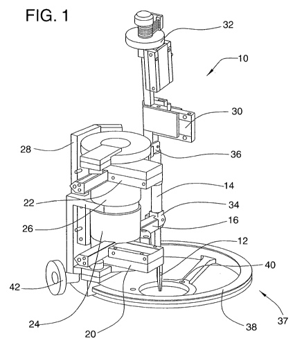
[0011] FIG. 1 is a front perspective view of an illustrative manipulator
constructed in accordance with the teachings of the present invention.
[0012] FIG. 2 is a rear perspective view of the manipulator of FIG. 1.
[0013] FIG. 3 is a block diagram of an illustrative control system for a
manipulator constructed in accordance with the teachings of the present
invention.
[0014] FIG. 4 is a perspective view of an alternative embodiment of a
manipulator constructed in accordance with the present invention supporting a
cautery/dissection tool.
[0015] FIG. 5 is a perspective view of the manipulator of FIG. 4 supporting a
drill.
CA 02682992 2009-10-05
WO 2008/134017 PCT/US2008/005393
4
[0016] FIG. 6 is a perspective view of the manipulator of FIG. 4 mounted to a
head clamp fixation system.
[0017] FIG. 7 is another perspective view of the manipulator of FIG. 4
mounted to a head clamp fixation system.
[0018] FIG. 8 is a perspective view of the manipulator of FIG. 4 further
including a position tracking mechanism which is illustrated schematically.
[0019] FIG. 9 is a schematic flow chart diagram of an illustrative method and
system including a haptic interface and a manipulator that is capable of
performing
reference frame transformations.
[0020] While the invention will be described and disclosed in connection with
certain preferred embodiments and procedures, it is not intended to limit the
invention
to those specific embodiments. Rather it is intended to cover all such
alternative
embodiments and modifications as fall within the spirit and scope of the
invention.
DETAILED DESCRIPTION OF THE PREFERRED EMBODIMENT
[0021] Referring now more particularly to FIG. I of the drawings there is
shown an illustrative embodiment of a surgical manipulator 10 constructed in
accordance with the present invention. The illustrated manipulator 10 can
interchangeably support and move a medical tool 12 with up to six degrees of
freedom. As will be appreciated, the invention is not limited to any
particular type of
medical tool rather any suitable tool can be used with the manipulator
including, but
not limited to, needle holders, staple or clamp appliers, probes, scissors,
forceps,
cautery, suction cutters, dissectors, drills, lasers, ultrasonic devices and
diagnostic
devices. The tools can be reusable, limited reuse or disposable. If the
medical tool
has moving parts that are conventionally human powered, the manipulator 10 can
be
adapted to accommodate an actuator dedicated to powering the tool such as for
example an electric, pneumatic or hydraulic actuator.
100221 In order to provide dexterity enhancement for an operator/surgeon in
performing surgical and certain interventional radiology procedures, the
manipulator
can be used as a slave robot in a master-slave robotic system. In such a
system, a
CA 02682992 2009-10-05
WO 2008/134017 PCT/US2008/005393
surgeon/operator provides position input signals to the "slave" manipulator
via a
master or 1laptic interface 13 which operates through a controller 15 or
control
console as in the schematic block diagram of FIG. 3. Specifically, through the
use of
an input device 17 on the haptic interface 13 such as a six degree of freedom
tool
handle with force feedback, joystick, foot pedal or the like, the surgeon
indicates the
desired movement of the tool 12 held by the manipulator 10. The haptic
interface 13
relays these signals to the controller 15, which, in turn, applies various
desired
predetermined adjustments to the signals prior to relaying them to the slave
manipulator. Any haptic interface having an equal or greater number of degrees
of
freedom (DOF) than the manipulator can be used to control the manipulator via
the
controller. Examples of haptic interfaces or masters which can be used with
the
present invention include the Freedom 6S available from MPB Technologies of
Montreal, Canada, and other haptic interfaces commercially available from
Sensable
Technology of Cambridge, Massachusetts and MicroDexterity Systems of
Albuquerque, New Mexico.
[0023] Based on the signals provided by the controller 15, the manipulator 10
executes the desired movement or operation of the tool 12. Thus, any desired
dexterity enhancement can be achieved by setting up the controller 15 to
perform the
appropriate adjustments to the signals sent from the haptic interface 13. For
example,
this can be accomplished by providing the controller 15 with software which
performs
a desired dexterity enhancement algorithm. Software dexterity enhancement
algorithms can include position scaling (typically downscaling), force scaling
(up-
scaling for bone and cartilage, downscaling for soft tissue), tremor
filtering, gravity
compensation, programmable position boundaries, motion compensation for
aneurysms, velocity limits (e.g., preventing rapid movement into brain, nerve
or
spinal cord tissue after drilling through bone), and, as discussed in greater
detail
below, image referencing. These and other examples of possible algorithms are
well
known in the field of robotics and described in detail in published
literature. The
ZMP SynqNet Series Motion Controllers which employ the SynqNet system and are
available from Motion Engineering of Santa Barbara, California are one example
of a
CA 02682992 2009-10-05
WO 2008/134017 PCT/US2008/005393
6
suitable controller for use with the present invention (see www.synqnet.org
and
www.motionen .g com). Another example of a suitable controller for use in the
present invention is the Turbo PMAC available from Delta Tau Data Systems of
Northridge, California.
[00241 To pernlit movement of the tool 12 with, in the illustrated
embodiment, six degrees of freedom, the tool is supported at a lower end of a
tool
support shaft 14 that can be translated in space via a system of rotary and
linear
actuators. More specifically, in the illustrated embodiment, the tool support
shaft 14
is supported by a pair of, in this case, vertically spaced support or control
arms 16, 18
each of which is independently movable via a respective linear actuator 20, 22
and a
respective rotary actuator 24, 26. As shown in FIGs. 1 and 2, the linear
actuator 20,
22 associated with each control arm 16, 18 is arranged so as to translate its
respective
control arm in a telescoping manner in a lengthwise direction. Each linear
actuator
20, 22 is connected, in turn, to the output shaft of its corresponding rotary
actuator 24,
26 so as to permit pivotal movement of the linear actuators 20, 22, and
thereby the
control arms 16, 18. In this case, the rotary actuators 24, 26 are arranged in
stacked
relation on a stationary support frame 28 such that their rotational axes are
aligned.
The rotary actuators, however, do not have to be in stacked relation as the
two
actuators 24, 26 can be independently located relative to each other.
[00251 Through the combination of the control arms 16, 18 and their
corresponding linear 20, 22 and rotary actuators 24, 26, the tool support
shaft 14 can
be moved in space in four degrees of freedom. For example, the manipulator 10
can
operate as a differential mechanism in that relatively large pitch and yaw
angles of the
tool support shaft 14 can be produced by rotating the rotary actuators 24, 26
for the
two control arms 16, 18 in opposite directions and by moving the linear
actuators 20,
22 for the two control arms in opposite directions. Additionally, the tool
support
shaft 14 can be moved like a cylindrical or polar coordinate robot by rotating
the
rotary actuators 24, 26 for the two control arms 16, 18 in the same direction
and by
moving the linear actuators 20, 22 for the two control arms in the same
direction.
CA 02682992 2009-10-05
WO 2008/134017 PCT/US2008/005393
7
100261 For moving the tool 12 in the lengthwise direction of the tool support
shaft 14 and to provide for rotation of the tool about the longitudinal axis
of the tool
support shaft, two additional actuators are provided. In particular a linear
actuator 30
is incorporated into the tool support shaft 14 which is operatively connected
to the
tool 12 (via a shaft or other means) so as to permit lengthwise movement of
the tool
12 in a telescoping manner relative to the longitudinal axis of the tool
support shaft
14. This lengthwise movement of the tool 12 relative to the tool support shaft
14 can
be used to insert and withdraw the tool 12 from the body of a patient. The
rotary
movement of the tool 12 is produced by a rotary actuator 32 arranged, in this
case, at
the upper end of the tool support shaft 14 and operatively connected to the
tool 12
(again, via a shaft or other suitable means) so as to enable rotation of the
tool 12 about
the longitudinal axis of the tool support shaft 14. The rotary movement of the
tool 12
relative to the tool support shaft 14 can be useful when using axially
asymmetric
tools, such as for example, scissors which extend at an angle with respect to
the tool
support shaft.
[0027] To permit movement of the tool support shaft in the desired degrees of
freedom each control arm 16, 18 is connected to the tool shaft 14 using an
appropriate
universal or gimbals joint. In the illustrated embodiment, the joints between
the
control arms and the tool support shaft comprise three degree of freedom
Hookes type
joints 34, 36. The joints between the tool support shaft and the control arms
should
provide six degrees of freedom to the tool shaft. This can also be
accomplished by
providing one joint which has two degrees of freedom and a second joint which
has
four degrees of freedom. Additionally, two joints each having two degrees of
freedom could be used with the tool shaft itself supplying the two additional
degrees
of freedom to the tool as shown in FIGS. I and 2.
100281 For sensing the positions of the various linear and rotary actuators
20,
22, 24, 26, 30, 32 and, in turn, the control arms 16, 18, joints 34, 36 and
tool support
shaft 14, the actuators can be equipped with position sensors 50. Each of the
linear
and rotary actuators can be in communication with the controller and the
position
sensors can provide position information in a feedback loop to the controller
as shown
CA 02682992 2009-10-05
WO 2008/134017 PCT/US2008/005393
8
in FIG. 3. For ease of reference, the position sensor for only one of the
actuators is
shown in FIG. 3. In one preferred embodiment, optical encoders are used to
sense the
positions of the various actuators, however, it will be appreciated that any
number of
different conventional position sensors can be used. Likewise, the various
actuators
can also be equipped with force sensors 52 (again, only one of which is shown
in FIG.
3) for sensing the forces or torques applied by the actuators so as to enable
a
determination of the forces and torques applied to the tool support shaft 14.
As
shown in FIG. 3, this information can again be provided in a feedback control
loop to
the controller 15, for example to allow force feedback to the input device of
the haptic
interface (shown schematically as line 56). Of course, any known method for
measuring forces and/or torques can be used, including, for example, foil type
or
semiconductor strain gauges or load cells.
100291 Another embodiment of a manipulator according to the invention is
shown in FIGS. 4 and 5 wherein components similar to those described above
have
been given similar reference numerals in the 100 series. The manipulator 110
of
FIGS. 4 and 5 is very similar in configuration and operation to that of the
manipulator
shown in FIGS. 1 and 2. In particular, the manipulator 110 shown in FIGS. 4
and
5 can move a tool 112 supported on a tool support shaft 114 in six degrees of
freedom. To this end, as with the FIGS. 1 and 2 embodiment, the tool support
shaft
114 is supported by a pair of spaced control arms 116, 118 each of which is
independently movable via a respective linear actuator 120, 122 and a
respective
rotary actuator 124, 126. The linear actuator 120, 122 associated with each
control
arm 116, 118 translates the control arm in its lengthwise direction while the
rotary
actuator 124, 126 can pivot the linear actuator and, in turn, the control arm.
The
manipulator 110 shown in FIGS. 4 and 5 also includes a linear actuator 130 on
the
tool support shaft 114 which facilitates tool insertion and withdrawal and a
rotary
actuator 132 on the tool support shaft which facilitates tool roll.
[0030] Unlike the manipulator shown in FIGS. 1 and 2, the rotary actuators
124, 126 are supported on a frame 128 such that their rotary axes are not
aligned. The
support frame 128, in this case, includes upper, lower and intermediate
support arms
CA 02682992 2009-10-05
WO 2008/134017 PCT/US2008/005393
9
129 between which the rotary and linear actuators are supported. The
illustrated
support frame 128 provides a relatively compact arrangement which can be
readily
connected to existing mounting arrangements as described in greater detail
below.
[00311 FIGS. 4 and 5 also illustrate how the manipulator of the present
invention can be used to support different tools. Specifically, as shown in
FIG. 4, the
manipulator 1 10 can support a tool 112, in the illustrated embodiment a
cautery/dissection tool, which is arranged coaxially with the tool support
shaft 114.
Alternatively, as shown in FIG. 5, a tool 112 (in this instance, a drill) can
be
supported in offset relation from the tool support shaft 114 in order to
accommodate,
for example, an actuator for a powered tool. In this case, the tool 112 is
connected to
the tool support shaft 114 via a connector piece 144 which permits the tool to
be
moved in space with the support shaft. Moreover, by connecting the tool 112 to
the
pivotable and extensible lower end of the support shaft 114, the tool can also
be
moved via the tool insertion linear actuator 130 and the tool roll rotary
actuator 132
on the support shaft. As will be appreciated, other arrangements can be used
to
mount the tool on the tool support shaft.
[0032] The construction and operation of the illustrated manipulators is
similar to several of the manipulator embodiments disclosed in commonly
assigned
PCT Application Serial No. PCT/US99/27650 and corresponding U.S. Application
Serial No. 09/856,453 entitled "Surgical Manipulator" the disclosure of which
is
incorporated herein by reference. As will be appreciated, while the
illustrated
manipulator geometry provides certain advantages including movement in six
degrees
of freedom, the present invention is not limited to a particular manipulator
architecture or kinematic scheme. Instead, all that is necessary is to provide
a
manipulator that is capable of moving a tool in a desired number of degrees of
freedoni. For example, other manipulator architectures and kinematic schemes
that
can be used include a so-called dual SCARA scheme such as disclosed in PCT
Application Serial No. PCT/US99/27650 and U.S. Application Serial No.
09/856,453
and a dual planar scheme such as disclosed in U.S. Patent Nos. 5,943,914 and
6,000,297 entitled respectively "Master-Slave Micromanipulator Apparatus" and
CA 02682992 2009-10-05
WO 2008/134017 PCT/US2008/005393
"Master-Slave Micromanipulator Method". Moreover, while the illustrated
embodiment only includes a single manipulator, two or more manipulators may be
provided such as for procedures which require more than one hand or arm.
[0033] In accordance with one important aspect of the present invention, to
substantially reduce the likelihood of patient movement relative to the
manipulator
10, 110 during a surgical or other interventional procedure, thereby enhancing
patient
safety, the manipulator 10, 110 can include a mounting fixture which permits
the
manipulator to be fixed relative to at least a particular portion of a
patient's body.
The ability to fix the manipulator 10, 110 relative to the patient's body
potentially
eliminates the need for general anesthesia and muscle paralytics, and the
associated
medical risks, as well as the need for active compliance and/or passive
backdriveabilty of the manipulator actuators.
[0034] To this end, in the embodiment illustrated in FIGS. 1 and 2, the
actuator support frame 28 and, in turn, the tool support shaft 14 are
connected to a
mounting structure 37, in this instance a mounting ring 38, which can be
mounted
directly to skull or other body part of a patient. To facilitate attachment of
the
mounting ring 38 to, for instance, the skull of the patient, the mounting ring
38
includes mounting holes 40 (three in the illustrated embodiment) which can
receive
screws that attach the mounting ring to the skull. The actuator support frame
28 is
connected to the mounting ring 38 by a clamping mechanism 42 which permits the
actuator support frame 28 to be moved and locked into any given position
around the
perimeter of the mounting ring 38.
[0035] An embodiment of the invention in which the mounting structure
includes a head clamp fixation system is illustrated in FIGS. 6 and 7. In the
illustrated embodiment, an arm 160 is provided which interconnects the support
frame 128 of the manipulator 110 of FIGS. 4 and 5 with a head clamp 162. The
clamp 162 includes a C-shaped frame 164 which supports a first fixed head
engaging
pin 166 on one side and second and third head engaging pins 168, 170 on the
opposite
side. The second and third head engaging pins 168, 170 are supported on a
clevis 172
that is rotatable relative to the frame 164 so as to allow a surgeon to adjust
the angular
CA 02682992 2009-10-05
WO 2008/134017 PCT/US2008/005393
11
position of the patient's head relative to the frame 164. The clamp 162
includes a
rotation mechanism 174 for releasably locking the clevis 172 in a particular
angular
position relative to the frame 164. In the illustrated embodiment, the head
clamp 162
is supported by a base unit 176 which allows the head clamp to be mounted to a
medical table.
[0036] To ensure that the manipulator 110 remains fixed relative to the
patient's head during adjustment of the position of the head, the arm 160
supporting
the manipulator is tied into the rotation mechanism 174 of the clamp 162. In
particular, the arm 160 is tied into a sleeve 178 which rotates with the
clevis 172 as
the angular position of the clevis is adjusted via a knob 180 on the rotation
mechanism 174. Thus, the manipulator I 10 remains fixed in the same position
relative to the clevis 172, and in turn the patient's head, during any
adjustment of the
head. One example of a head clamp fixation system that can be used in the
present
invention is sold under the tradename MAYFIELD by Ohio Medical Products of
Cincinnati, Ohio (see, e.g. U.S. Patent 5,269,034 and U.S. Patent 5,546,663).
[0037] Of course, as will be appreciated by those skilled in the art, the
present
invention is not limited to any particular mounting fixture, but rather
extends to any
mounting fixture or system which allows the manipulator to be fixed relative
to a
desired portion of the patient's body. Nor is the present invention limited to
being
mountable to any particular location on the body. For instance, the
manipulator 10
can be mounted to the skull (e.g., to perform neurosurgery, ear surgery or
nasal
surgery), the spine or other bony structures.
100381 In order to permit mounting of the manipulator 10 to a patient, the
manipulator 10 must have a relatively lightweight, compact design that has a
relatively low inertia. Utilizing a lightweight, compact manipulator, helps
alleviate
the need to provide alternative support structures to relieve some of the
weight
exerted on the patient. While such support structures help reduce some of the
stress
on the patient caused by a manipulator, they can introduce significant inertia
problems. To achieve the low mass and inertia, linear and rotary actuators
having a
relatively high force to mass ratio should be used in the manipulator. To this
end, in
CA 02682992 2009-10-05
WO 2008/134017 PCT/US2008/005393
12
one presently preferred embodiment of the invention, the linear and rotary
actuators
(20, 22, 24, 26, 120, 122, 124, 126) used in the manipulator comprise
ultrasonic
motors.
[0039] Besides a very high force to mass ratio, ultrasonic motors provide
several other advantages over conventional stepper and DC motors. For example,
ultrasonic motors have intrinsic braking when powered down at a force
equivalent to
its force when moving. This provides increased patient safety. Ultrasonic
motors do
not have heat dissipation issues and can be isolated electrically. Moreover,
ultrasonic
motors are very stable so as to permit use in clean rooms. Additionally, as
compared
to pneumatic actuators, actuators based on ultrasonic motors do not have
overshoot
problems when the tool is used to apply a force on a rigid body which then
breaks
free. One example of an ultrasonic motor suitable for use as either a linear
or rotary
actuator in the present invention is the SAW Ultrasonic Motor available from
Nanomotion of Yokeneam, Israel (described in U.S. Patent 5,453,653).
[0040] Alternatively, electrodynamic motors, hydraulic actuators or cable
drives could also be used as the linear and rotary actuators on the
manipulator. With
respect to cable drives, either rotary or push-pull could be used. The prime
movers
for the cables can include air or fluid turbines or servo motors. When using
cable
drives, significant torque amplification would have to take place through the
controller in order to compensate for the effects of backlash, windup,
hysteresis and
cable friction. If hydraulic actuators are used for the linear and rotary
actuators,
water, saline, or perfluorocarbon liquids can be used for hydraulic actuation
to ensure
patient safety in the event the hydraulic fluid comes into contact with the
patient.
Gear pumps or other suitable pumps like peristaltic, diaphragm, piston and
venturi
pumps can be used to control the flow of hydraulic fluid which is relatively
incompressible compared to pneumatic actuation thereby avoiding overshoot
problems. The actuators themselves can comprise, for example, piston/cylinder
actuators (linear actuators), rotary vane, diaphragm and Bourdon tubes. To
reduce
static and dynamic friction, hydrostatic bearings can be used for the rotary
and linear
CA 02682992 2009-10-05
WO 2008/134017 PCT/US2008/005393
13
actuators. Other types of actuators having high force to nlass ratios could
also be
used.
[0041] According to a further aspect of the present invention, the capability
of
fixing the manipulator 10, 110 relative to the patient also can provide
enhanced
precision of the registration of the manipulator 10 and the tool 12, 112 with
respect to
the patient. In particular, fixing the manipulator 10, 110 relative to the
patient
provides a constant mechanical reference so that images or constant subsets of
image
data acquired prior to or earlier in the procedure will remain in the same
position
relative to the manipulator 10, 110 as the procedure progresses.
[0042] With the embodiment of the invention shown in FIGS. 1 and 2, one
method by which this can be accomplished is to perform preoperative imaging
(e.g.,
magnetic resonance (MR) or X-ray) with the screws to be used to fix the
manipulator
to the patient already implanted in the patient. The screws, which can be made
of
a MR or X-ray compatible material, can then act as reference points or
fiducials in the
images. At the time of surgery, the screws are used to define the mounting
points for
the manipulator mounting ring 38. Then, as the operation is performed, the
position
of the tool 12 can be rendered against the preoperative image. If desired,
during the
procedure, the image data against which the position of the tool 12 is
rendered can be
updated using, for example, CT, MR or the like.
[0043] As an alternative to performing the preoperative imaging with the
mounting screws in place, the position of the tool 12, 112 and the mounting
structure
or the manipulator mechanism 10, 110 can be tracked relative to a pre- or
intra-
operative image using optical triangulation by integrating the manipulator
into a
StealthStation system available from Medtronic of Minneapolis, Minnesota or
by
using another three dimensional, six degree of freedom position sensing
technology
well known in the field of neuro, spine and other types of surgery such as,
for
example, electromagnetic tracking.
100441 An electromagnetic tracking or guidance system can be based, for
example, on sensitivity to magnetic field strength, phase delay, phase versus
position
or pulse time of travel measurements to calculate a position and orientation
of the tool
CA 02682992 2009-10-05
WO 2008/134017 PCT/US2008/005393
14
with any degree of certainty from one to six degrees of constraint. One way in
which
this can be accomplished is to use an electromagnetic field generator 90
comprising,
for example, three orthogonally disposed coil loops which are capable of
producing a
multidimensional field in three dimensions such as shown schematically in FIG.
8.
The magnetic fields produced by each of the three coils can be mutually
distinguishable from one another via either phase, frequency or time
multiplexing.
Remote sensors 92 for detecting the field generated by the field generator,
which
could comprise three orthogonally disposed dipole sensing elements, can be
placed on
the tool and in other locations such as on the manipulator as shown in FIG. 8.
The
position of the remote sensors 92 relative to the field generator 90 can then
be
monitored and correlated with stored preoperative images by a position
detection
controller 94 and shown on a display 96. The position detection controller
could be
the same controller used to control movement of the manipulator or a different
controller.
[0045] These types of electromagnetic positioning techniques are used with
global positioning systems, radar, resolvers and other electromagnetic
position
determining systems. Such an electromagnetic tracking or guiding system is not
limited to use with the particular manipulator configurations disclosed herein
but
rather can be used to track and/or guide any type of tool that is supported
and moved a
manipulator or robot in one or more degrees of freedom. Electromagnetic
position
systems that can be adapted for use with the present invention are available
from
Visualization Technologies of Boston, Massachusetts (see, e.g., U.S. Patent
5,676,673
and U.S. Patent 5,829,444), UltraGuide of Lakewood, Colorado and Polhemus of
Colchester, Vermont
100461 During a medical procedure, it is possible that the manipulator 10, 110
and haptic interface 13 will be tilted or rotated with respect to one another
such that
they are in different orientations with respect to the patient. For example,
the patient
may be placed in a specific orientation in order to allow viewing of the
surgical site
with, for example, a microscope. The manipulator 10, 110 will then be arranged
so
as to provide the best access to the surgical site without obscuring the view
of the
CA 02682992 2009-10-05
WO 2008/134017 PCT/US2008/005393
surgical site. The haptic interface, in turn, will be oriented to provide a
good
ergometric and comfortable position for the surgeon's hand arm. In such a
case, it is
likely that the coordinate reference frames of the manipulator and haptic
interface will
be skewed from one another and with respect to the patient.
[0047] The surgeon operating the manipulator through the haptic interface
will be observing the tool 12 held by the manipulator 10, 110 and the surgical
site
during a surgical procedure. Accordingly, the position tracking system (which
can be
electromagnetic, optical or any other suitable system) and accompanying
position
detection controller can be adapted to specifically locate the manipulator,
haptic
interface and patient and to perform any necessary translations of movements
in the
haptic interface reference frame and manipulator reference frame with respect
to the
coordinate reference frame of the patient. These translations can be
performed, for
example, by a translation algorithm executed by the controller and can
coordinate
movement of the haptic interface input device and the tool held by the
manipulator
with respect to the patient's frame of reference regardless of the orientation
of the
haptic interface and manipulator relative to each other and the patient. Thus,
when a
surgeon moves his hand forward straight and level using the haptic interface,
the
medical tool held by the manipulator will also move in the same trajectory
even if the
manipulator is mounted in a skewed orientation relative to the patient.
[0048] The haptic interface and manipulator reference frames are generally
defined by their respective mounting positions. However, that is not the case
with the
patient reference frame. In particular, the patient reference frame could
depend on the
position of the patient or perhaps if the procedure is being performed with
the
assistance of a microscope or some sort of other imaging technology, the
patient
reference frame could depend in some measure on the reference frame of the
image.
Accordingly, the patient coordinate reference frame may be the same or it may
be
offset from the coordinate reference frame of the haptic interface as desired
for a
particular medical procedure. As with the orientations of the haptic interface
and the
manipulator, the orientation of the patient reference frame can be a system
input or it
could be input into the controller in some other fashion, such as manually.
Once the
CA 02682992 2009-10-05
WO 2008/134017 PCT/US2008/005393
16
orientations of the desired patient, llaptic interface and manipulator
reference frames
relative to one another are known, the controller can perform any necessary
translations or adjustments of the movement information generated via the
haptic
interface so that the movement commands or instructions provided to the
manipulator
by the controller provide the desired movement of the medical tool in the
patient
reference frame.
[0049] A schematic flow chart showing an exemplary system capable of
performing such reference frame transformations for a master-slave robot
system is
provided in FIG. 9. In the system shown in FIG. 9, a position tracking or
sensing
system 200 is used to sense the orientations of the coordinate reference
frames of the
manipulator 10, the haptic interface 13 and the patient. Data regarding the
orientations of these reference frames is then communicated to the controller
15,
which determines the relative orientations of the manipulator, haptic
interface and
patient reference frames. This data or information regarding the relative
orientations
is then used to adjust the movement commands received from the haptic
interface 13
to produce movement instructions that are communicated to the manipulator 10.
[0050] Many surgical procedures involve removing viable tissue, such as
bone, so as to be able to make an implant into the viable tissue such as a
bone or
removing undesired tissue from other viable tissue. In such cases, it can be
advantageous to define the patient reference frame using the viable tissue.
For
example, the patient reference frame can be defined by the bone into which an
implant will be placed. However, living bone is very difficult to completely
constrain
into a fixed position during a medical procedure. Consequently, the bone can
move
during a procedure due to contact forces or other external stimuli resulting
in a shift in
the orientation of the patient reference frame.
[0051] To account for such movement, the position sensing system or some
other movement monitoring system can be adapted to continually rr-onitor
movement
of the bone or other viable tissue defining the patient reference frame on a
real time
basis. This can be accomplished, for example, by attaching movement monitoring
devices directly to the viable tissue. The resultant data can then be used by
the
CA 02682992 2009-10-05
WO 2008/134017 PCT/US2008/005393
17
controller to continually update, again on a real tinle basis, the data on the
relative
orientations of the patient, haptic interface and manipulator to account for
any
movement of the bone so that the adjustments made by the controller to the
haptic
interface movement information always use the most current information
regarding
the position of the bone or other viable tissue. Thus, instead of having to
halt further
movement or operation of the medical tool, the medical procedure can proceed
without interruption with the manipulator automatically moving the tool to
follow the
moving bone.
[0052] FIG. 9 illustrates an embodiment of the invention in which the position
sensing system 110 used to detect the orientations of the manipulator, haptic
interface
and patient reference frames is also used to detect movement of the desired
body
tissue. In the FIG. 9 embodiment, the position sensing system updates the data
or
information concerning the orientation of the patient reference frame if
movement of
the body tissue is detected. The new data regarding the orientation of the
patient
reference frame is then directed to the controller which uses the new patient
reference
frame to re-calculate the relative orientations of the manipulator, haptic
interface and
patient reference frames. As noted above, this detecting of movement and
updating of
the patient reference frame orientation data is done on a real time basis as
is the
updating of the relative orientation data by the controller. Of course, the
system could
be adapted to also monitor movement of other elements of the system on a real
time
basis such as the haptic interface and/or the manipulator.
[0053] The controller can manipulate the data regarding movement of the
bone in any suitable manner so long as the system as a whole takes into
account the
movement of the bone when generating the movement commands for the
manipulator. For instance, the controller could be set-up to use the data
regarding
movement of the bone to continuously update the position of the manipulator
reference frame relative to the bone (i.e. patient reference frame) on a real
time basis
so that the manipulator will move in such a way to follow movement of the
bone. As
will be appreciated by those skilled in the art, a position/movement sensing
system
that is able to detect movement of the bone at a very high bandwidth should be
used
CA 02682992 2009-10-05
WO 2008/134017 PCT/US2008/005393
18
and the controller should be capable of taking that bone movement data and
updating
the reference frame transformations at a sufficiently high servo speed to
enable
continuous operation of the manipulator despite movement of the bone.
[0054] As will be understood by those skilled in the art, the relative
orientations of the coordinate reference frames defined by the haptic
interface, the
manipulator and the patient can be determined using any number of different
position
tracking or navigation systems and the present invention is not limited to any
particular method. For instance, as noted above, the orientations of the
haptic
interface, manipulator and patient reference frames can be sensed using an
electromagnetic position sensing system. In such case, the position of the
haptic
interface, manipulator and patient (e.g., the tissue subject to the medical
procedure)
can be determined by trilateration on a localized basis in a similar manner to
a global
positioning system via wireless connections or links between a transmitter and
receivers. For instance, the operating room or surgical unit can have several
fixed
transmitters in defined locations and each of the haptic interface,
manipulator and
patient can have associated receivers that can receive signals from the
transmitters
and generate position data. Sufficient receivers (and/or transmitters) would
have to be
provided on each of the haptic interface, manipulator and patient so as to
define in
three dimensions the orientation of the reference frames of each.
Alternatively, the
transmitters could be provided on the haptic interface, manipulator and
patient and the
receivers can be fixed in a defined location.
[0055] An optical positioning system is another type of positioning system
that could also be used to define the relative orientations of the haptic
interface,
manipulator and patient. An inertia based position tracking system, such as
using
gyroscopes that are arranged on the haptic interface, manipulator and patient,
could be
used. A laser range scanner based position detection system is yet another way
to
sense the relative orientations of the haptic interface, manipulator and
patient
reference franies.
100561 In accordance with yet another aspect of the present invention, the
manipulator 10, 110 can be constructed so as to be compatible with an MR or X-
ray
CA 02682992 2009-10-05
WO 2008/134017 PCT/US2008/005393
19
environment. This would allow the manipulator 10 to operate within and during
a
MR imaging or other X-ray procedure, thereby enabling the surgeon to
visualize, for
example, the target tissue, normal tissue and the tool 12, 112 in the same
real-time or
near real-time imaging environment. In order to allow the manipulator 10, 110
to
operate in a MR environment, the manipulator must be constructed entirely of
MR
imaging compatible materials such as certain metals, plastics, glass and
ceramics.
Additionally, the linear and rotary actuators 20, 22, 24, 26, 120, 122, 124,
126 used in
the manipulator must also be compatible with MR imaging. In this regard, both
ultrasonic and hydraulic actuators have the additional advantage of being MR
compatible. In order to permit the manipulator 10, 110 to be used while
performing
X-ray imaging, certain components of the manipulator can also be made of
radiolucent materials such as plastics, graphite, ceramics and glass. The
position
encoders and force sensors associated with the actuators also can be made MR
and/or
X-ray imaging compatible. For example, fiber optic connected sine-cosine
optical
encoders, such as are commercially available from MicroE, Renishaw or Computer
Optical Products, can be used for the position encoding and piezoelectric
strain
gauges for the force sensing.
[0057] From the foregoing, it will be appreciated that the present invention
provides a lightweight and compact patient mountable manipulator that can be
used in
a master-slave robotic system to enhance the dexterity of a operator/surgeon.
The
capability of fixing the manipulator relative to the body of a patient
provides
enhanced safety by substantially reducing the likelihood of trauma caused by
unintentional movement of the patient relative to the manipulator. Moreover,
fixing
the manipulator relative to the body of the patient provides a very precise
mechanical
reference which facilitates tracking of the medical tool with respect to a pre-
and/or
intra-operative image. The manipulator can be constructed such that it can be
operated while performing MR or X-ray imaging so as allow to the position of
the
tool to be referenced to a real-time or near real-time image. Thus, the
lightweight,
compact manipulator of the present invention and its capability of operating
in up to
six degrees of freedom in a relatively large workspace makes the invention
suitable
CA 02682992 2009-10-05
WO 2008/134017 PCT/US2008/005393
for use in any number of different medical procedures including, for example,
neurosurgery, ear surgery, sinus surgery and spine surgery.
[0058] All of the references cited herein, including patents, patent
applications, and publications, are hereby incorporated in their entireties by
reference.
[0059] While this invention has been described with an emphasis upon
preferred embodiments, it will be obvious to those of ordinary skill in the
art that
variations of the preferred embodiments may be used and that it is intended
that the
invention may be practiced otherwise than as specifically described herein.
Accordingly, this invention includes all modifications encompassed within the
spirit
and scope of the invention as defined by the following claims.