Note: Descriptions are shown in the official language in which they were submitted.
CA 02683121 2009-10-06
WO 2008/107869 PCT/IL2008/000252
1
Multi-Stiffness guidewire
Field of the Invention
The present invention relates to the field of minimal
invasive catheterization. More particularly, the invention
relates to a method and device for opening and/or removing
obstructions occluding body internal passages by means of
an active guidewire. More particularly, the invention
relates to an improved active oscillating guidewire with
varying stiffness to enable a safe crossing through an
occluded vessel.
Background of the Invention
Many vasocclusive events, such as heart attacks and
strokes, are caused by plaque build-ups in arteries. As one
specific example, atherosclerotic plaque i=s known to build-
up in the walls of arteries in the human body. Such plaque
build-up restricts circulation and often causes problems,
for example cardiovascular problems, especially when the
build-up occurs in coronary arteries.
One common method for opening partially occluded body
internal passages is to guide a medical device to the
diseased site, where it is used to carry out the needed
treatment. A guidewire is usually used for advancing a
catheter device thereover via body internal passages
towards the treatment site. Typically, the distal tip of
the guidewire is introduced into the body of the treated
subject via an incision and advanced therethrough towards
the treatment site, thereby forming a path leading to the
occluded site through said body internal passages. A
catheter, or any other suitable treatment devices (e.g.,
CA 02683121 2009-10-06
WO 2008/107869 PCT/IL2008/000252
2
balloon catheter, stent, rotational atherectomy device,
laser device etc), may be then threaded over the guidewire
and advanced through said internal passages using the
guidewire as a rail.
In those cases as described above, regular guidewires are
used. These regular guidewires are having a distal tip with
low stiffness. The low stiffness is of the order of 1 gram,
and therefore is safe for use: it cannot perforate the
vessel wall or dissect into the vessel wall. These
guidewires are sometimes also called a-traumatic, as they
are safe and "gentle" while being threaded via the vessels.
However, sometimes the low stiffness of these guidewires is
not sufficient to pass through complicated lesions, such as
total or near-total occluded vessels.
Total or near-total occlusions in body internal passages
can, partially or entirely, block the passage therethrough.
For example, in patients who suffer from coronary chronic
total occlusion (CTO), the successful performance of a
Percutaneous Transluminal Coronary Angioplasty (PTCA) is a
technical challenge. The factor that is most determinative
of whether the physician can successfully perform PTCA on
patients suffering from coronary CTO is his ability (or
inability) to advance a suitable guidewire from a position
proximal of the lesion to a position distal of the lesion
while remaining inside the true vessel lumen (without
performing perforation of the artery wall).
In some instances, such as where the occlusive matter is
soft or where the body internal passage is partially
CA 02683121 2009-10-06
WO 2008/107869 PCT/IL2008/000252
3
occluded, the guidewire can easily be pushed through the
occlusive matter itself, thereby allowing the guidewire to
remain within the body internal passage. However, in other
cases, such as when the body internal passage is totally
occluded by hard plaque (e.g., calcified atherosclerotic
plaque), the guidewire cannot cross the occlusion and may
deviate to the side and penetrate through layers of the
passage walls (e.g., the intima - inner layer of a vessel
wall), thereby creating a neo-lumen therethrough (e.g.,
through the sub-intimal space - within the wall of the
artery between the intima and media, or adventitia i.e. a
dissection), or even completely exit said internal passage
i.e. perforate the passage wall.
To enable the treatment of these complicated cases in
general, and more particularly Chronical total occlusions
(CTO) cases, special guidewires have been developed and
introduced into market.
Such guidewires for treating CTO are generally built such
that the distal portion of the guidewire is stiffer than
that of a regular guidewire. This higher"stiffness results
in a better penetration capability into hard / calcified
tissues in. general and totally occluded vessels in
particular. Yet, this increased stiffness, often tends to
increase the risk of using them, as they can perforate the
vessel wall.
The way a physician, is handling a guidewire is by
manipulating the guidewire from its proximal side, i.e.
from the side outside the body of the patient.
CA 02683121 2009-10-06
WO 2008/107869 PCT/IL2008/000252
4
The manipulation is a combination of pushing / pulling and
rotating the guidewire until it passes the partially or
totally occluded zone.
When using any guidewire, including those with high
stiffness, the physician has limited control over the
guidewire, as he is manipulating it only from its proximal
end.
The configuration of the guidewire, together with the way
the physician is manipulating the guidewire, sets a limit
in the performance of the said guidewire, i.e. if a
physician is selecting a regular stiffness guidewire, this
selection, although, will not be suitable for CTO cases. In
other cases when the physician selects a high stiffness
guidewire, he may be able to pass through a CTO however the
risk of using such a guidewire is significantly higher, for
the reasons set out above.
Currently there is no guidewire available which enables the
physician to change its stiffness depending on the kind of
lesion he is trying to cross while the guidewire is already
threaded into the vessel. Moreover, there is no guidewire
available that inherently can cross a CTO in a safe manner,
due the need for new manipulations the physician is
required to carry out in addition to the' already existing
ones.
It would be desirable to have a guidewire with more than a
single stiffness zone, providing the physician with:
= The capability to select the stiffness of the
guidewire during the procedure, while the guidewire
is already threaded into the vessel.
CA 02683121 2009-10-06
WO 2008/107869 PCT/IL2008/000252
= Manipulating the guidewire in its high stiffness
mode, with an additional new mode of operation /
manipulation that is inherently safe to the vessel
wall and still capable of crossing CTO's.
5
It is an object of the present invention, to provide a
method and device for opening occluded body internal
passages and of body organs, by providing a guidewire
comprising at least two zones of different stiffness
levels.
Summary of the Invention
Guidewires are a great technical and clinical challenge.
The structure of the guidewire, and generally speaking
composition of materials and dimensions of the different
segments of the guidewire set the guidewire
characteristics. More specifically, most of the guidewire
are built in a way that their distal portion (typically the
distal 100 - 300 mm) are made of a special shaped / tapered
core, wrapped with a special spring like coil. This coil,
together with the inner shaped core of the guidewire,
influences dramatically the stiffness of the guidewire,
behavior and characteristics.
According to the present invention, the weakest stiffness
portion of the guidewire will not be at the most distal
portion of the guidewire, but rather proximally to this
portion. The most distal portion of the guidewire will then
have a higher stiffness level.
CA 02683121 2009-10-06
WO 2008/107869 PCT/IL2008/000252
6
An active engine, capable of providing longitudinal force
is implemented in between the weakest stiffness portion of
the guidewire and the most distal portion of the guidewire.
When a physician is manipulating the guidewire from its
proximal end, the guidewire is will perform similarly as
common single stiffness guidewire, with the result that the
physician cannot apply a pushing force which is higher than
the weakest portion of the guidewire.
However, when the physician needs to penetrate a hard /
calcified occlusion, he then activates the engine that is
pushing the distal portion of the guidewire internally,
hence not limited by the weakest portion of the guidewire,
and capable of reaching the higher level of stiffness of
the guidewire.
It is a further object of the present invention to provide
alternatives for internal engines, to be added to the
invented guidewire between the distal portion and the
weakest portion.
The present invention is directed to a multi-stiffness
guidewire structure.
In an embodiment according to the present a guide wire
having a distal portion is divided into several segments as
listed below:
= The most distal segment is designed to have a
stiffness level X.
CA 02683121 2009-10-06
WO 2008/107869 PCT/IL2008/000252
7
= The segment of the guidewire preceding this distal
segment is designed to carry an internal engine.
= The third segment preceding this second portion is
designed to have a stiffness level Y, which is lower
then stiffness level X.
= Additional segments may precede - the said third
segment, with either space for a further internal
engine or with a stiffness which may be of yet a
different level Z.
In another embodiment of the present invention, the
guidewire comprises dual stiffness segments follow:
= The most distal segment is designed to have a
stiffness level X. X is preferably designed to be in
the range of 3 to 12 grams
= The segment of the guidewire preceding this distal
segment is designed to carry an internal engine.
= The third segment preceding this second portion is
designed to have a stiffness level Y. Y is preferable
designed to be approximately 1 gram.
In yet another preferred embodiment of the present
invention, the dual stiffness guidewire comprises a distal
portion of a length range of 50 to 400mm. This distal
portion is constructed of an inner core wrapped with a
coil. The shape and dimension of the inner core sets the
stiffness of the said guidewire. Accordingly, the preferred
embodiment comprises of the following structure:
= First segment: The most distal portion of the
guidewire comprises an inner core shape suitable to
penetrate CTOs with a stiffness of 3 12 grams.
CA 02683121 2009-10-06
WO 2008/107869 PCT/IL2008/000252
8
= Second segment: At a distance of typically 50 - 100
mm, the internal engine is added. Since the same inner
core is used, it will have the same stiffness of the
most distal portion of the guidewire
= Third segment: Preceding that second segment, the
inner core tapers to a lower diameter than that of the
second segment, designed to have a stiffness of
typically 1 gram.
= Forth segment: preceding that third segment, the inner
core tapers to a larger diameter to provide a high
stiffness segment, typically higher than the
stiffnesses of all preceding segments and setting the
stiffness of the guidewire.
= Preceding that fourth segment, the inner core
continues all the way to the proximal side of the
guidewire.
In yet another preferred embodiment of the present
invention, the engine provided in the second segment
comprises magnetic beads added to the guidewire, housed in
a coiled support catheter. A more detailed description of
this optional engine appears in copending application
PCT/2006/000541. -
In a further preferred embodiment of this invention the
engine added to the guidewire comprises of embedded coils
that are part of the guidewire, housed in a support
catheter having magnetic beads. A more detailed description
of such an optional engine appears in copending Israel
patent application 179618.
CA 02683121 2009-10-06
WO 2008/107869 PCT/IL2008/000252
9
In alternative configurations of this invention, the second
segment may be designed for both carrying the internal
engine, as well as being designed to provide the guidewire
with its weaker stiffness portion.
This basic structure of the guidewire can be repeated
several times, thus providing a guidewire with several
levels of stiffnesses.
Thus the present invention provides guidewire for inducing
in-vivo vibrations in a body passageway or an organ,
comprising:
distal and proximal portions, the di.stal portion being
connected to the proximal portion;
the distal portion comprising at least two segments each
having a different stiffness, the most distal segment
having a stiffness higher than the segment preceding it;
and
a miniature engine embedded in a segment connecting said
two segments.
All of the above mentioned parameters are given by way of
example only, and may be changed in accordance with the
different requirements of the various embodiments of the
present invention. Thus, the abovementioned parameters
should not be construed as limiting the scope of the
present invention in any way. In addition, it is to be
appreciated that the different wires, inner cores, and
other members, described hereinabove may be constructed in
different shapes (e.g. having oval, square etc. form in
CA 02683121 2009-10-06
WO 2008/107869 PCT/IL2008/000252
plan view) and sizes differing from those exemplified in
the preceding description. -
The above examples and description have been provided only
5 for the purpose of illustration, and are not intended to
limit the invention in any way. As will be appreciated by
the skilled person, the invention can be carried out in a
great variety of ways, employing more than one technique
from those described above, all without exceeding the scope
10 of the invention.
Brief Description of the Drawings
Figure 1A shows the general structure a prior art
guidewire. Figure 1B illustrates the stiffnesses supported
by a prior art guidewire at different segments.
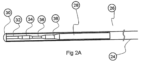
Figure 2A shows a preferred embodiment of a dual stiffness
structure guidewire according to the invention.
Figure 2B shows another embodiment of a dual stiffness
structure guidewire according to the invention.
Figure 3A shows an area of interest where alternatives of
engines can be implemented.
Figures 3B and 3C show different type of miniature engines
assembled in the middle section of a guidewire according to
the invention.
Detailed Description of Preferred Embodiments
Figure 1A shows a typical guidewire taken from the prior
art.
CA 02683121 2009-10-06
WO 2008/107869 PCT/IL2008/000252
11
Generally speaking the guidewire is divided into 2 main
zones.
Working zone 8, which is eventually inserted bare into the
human body vessel, and the rest of the guidewire 10, which
in most cases does not touch the vessel,., walls, as it is
typically housed in a catheter. The overall length of
typical guidewires varies in the range of from about 160 to
about 300 cm. The working zone 8 is divided into several
segments. The front or distal tip of the guidewire 2 is the
first part of the guidewire that touches the organ, and
must be designed in a way so as to not harm the organ or
vessel wall. A core member 4 precedes the distal tip of the
guidewire, encased by a spring type envelope 12. The
segment set by the core member 4, is typically the flexible
zone of the guidewire enabling it to safely and
conveniently propagate thru the vessel. This core member 4
sets also the stiffness level of the said guidewire.
Typically a second, thicker core member 6 precedes the
first core member 4, forming a less flexible zone, also
called "stent zone". This member 6 then is connected to the
last core member 8, which is an even thicker and stronger
core, used to enable the pushing and steering of the
guidewire along and inside the vessel. Some guidewires may
different numbers of zones and thus different numbers of
core members of varying thickness than described in this
figure, so as to fit special clinical needs. The core
members may be encased by spring type coils 12, which in
turn may be coated with special coatings, such as
hydrophilic coating 14.
Figure 1B shows the same prior art guidewire. Core member 4
has the lowest stiffness level designated as S1. The member
CA 02683121 2009-10-06
WO 2008/107869 PCT/IL2008/000252
12
6 preceding the said first segment 4 has a stiffness
designated as S2. In such a known guidewire Sl is lower
than S2.
Figures 2, describes two alternative embodiments according
to this invention.
In Figure 2A guidewire 26 comprises a distal working zone
28, and a proximal side 24, of the guidewire. The distal
working zone 28 is made up of several distal segments. The
most distal segment is the tip 30 of the guidewire. This
tip is connected to the front distal core member 32 of the
guidewire. This segment has a stiffness designated with S3.
Preceding that segment is the miniature engine segment 34.
The stiffness the segment that carries the miniature engine
may be designed to be of different levels, by controlling
the shape and dimensions of the core member of this
segment. However in general it would be a relatively high
stiffness, designated as S4. Preceding the engine segment
34, there is the weakest stiffness segment 36, with a
stiffness level designated as S5. This segment 36 is
preceded by the stent segment 38, with a typically higher
stiffness level than all previous segments. The stiffnesses
of the different segments according to this invention obey
the rule that S3 is stiffer than S5. Having these 2
stiffness zones, the guidewire can be designed to suit
complicated clinical applications, such as CTOs. The S3
level is typically designed to be in the range of 3 - 12
grams. The' S5 level is typically designed to be in the
range of 1 to 3 grams. When the physician is manipulating
the guidewire from its proximal side 24, he can apply a
force bigger than S3, hence the guidewire is safe. When
CA 02683121 2009-10-06
WO 2008/107869 PCT/IL2008/000252
13
reaching a complicated clinical case, such as CTO, the
physician can remotely operate the miniature engine (not
shown in this figure) that is embedded into the engine
segment 34, hence producing a distal force that can reach
the level of S3. The miniature engine may be of the type
disclosed in copending patent PCT/IL2006/000541 and / or
copending Israeli patent application number IL179618.
Figure 2B shows an alternative embodiment according to this
invention. The guidewire is built in a similar way to the
guidewire shown in Figure 2A, however the distal section
comprises only 3 segments: The first segment 42 is a front
segment with stiffness level designated as S10, preceded by
the weakest segment 44 with stiffness level designated as
S11, which also serves as the segment for implementing the
miniature engine, and preceded by the stent segment 38. In
this embodiment, as in the one shown in Figure 2A, the
physician is manipulating the guidewire from it proximal
side, hence cannot produce a force with stiffness larger
than S12 which is the stiffness of the weakest segment 44.
However if the physician selects to remotely operate the
miniature engine embedded in segment 44, he can reach a
stiffness level limited by the stiffness S10, which is the
stiffness level of the front distal segment 44.
It should be noted, that it is possible to build the
guidewire according to the invention in different
configurations with different stiffnesses and more segments
than shown in Figures 2A and 2B.
Figure 3A shows a close up view 60 on the engine segment of
a guidewire according to this invention.
CA 02683121 2009-10-06
WO 2008/107869 PCT/IL2008/000252
14
Figure 3B shows a guidewire where at least part 62 of the
coil wrapped around the distal tip is active and can
produce magnetic flux. This flux when put in a magnetic
field gradient, creates a force working on this section. A
detailed description of such engine can is given in
copending Israeli patent number IL179618.
Figure 3C shows another embodiment of an embedded miniature
engine. The engine in this configuration is made of small
magnetic beads 64 and 66 attached radially to the
guidewire. When this magnet bid is put in a magnetic field
gradient, a force is developed. A detailed description of
such miniature engines is given in copending PCT patent
application number PCT/2006/000541.
It should be mentioned, that other miniature engines that
can be operated remotely form the proximal side of the
guidewire may be implemented, and the configurations of the
guidewire also cover these options.
All of the above described parameters are given by way of
example only, and may be changed in accordance with the
different requirements of the various embodiments of the
present invention. Thus, the abovementioned parameters
should not be construed as limiting the scope of the
present invention in any way. In addition, it is to be
appreciated that the different wires, segments, magnets,
and other members, described hereinabove niay be constructed
in different shapes (e.g. having oval, square etc. form in
plan view) and sizes differing from those exemplified in
the preceding description.
CA 02683121 2009-10-06
WO 2008/107869 PCT/IL2008/000252
The above examples and description have of course been
provided only for the purpose of illustration, and are not
intended to limit the invention in any way. As will be
appreciated by the skilled person, the invention can be
5 carried out in a great variety of ways, employing more than
one technique from those described above, all without
exceeding the scope of the invention.