Note: Descriptions are shown in the official language in which they were submitted.
CA 02683182 2009-10-16
WIRING STANDARD SELECTOR SWITCH
FIELD OF THE INVENTION
The present invention relates to wired computer network technologies. In
particular, the present invention relates to a wiring standard selector switch
capable
of switching between multiple wiring standards used in wired computer
networks, such
as, cross-over and straight through, for example.
BACKGROUND OF THE INVENTION
The present invention is an improvement over Canadian Patent Application No.
2,658,088, filed March 11, 2009 wherein a universal network cable and a wiring
standard selector switch are disclosed. Further developments have been
revealed that
outline the need for the production of an upgraded wiring standard selector
switch. For
a ready understanding of the current state of the wiring standard selector
switch the
reader is directed to Canadian Patent Application No. 2,658,088.
Wired computer networks generally consist of a plurality of network devices
connected to each other using a plurality of network cables to enable data
communication between each of the network devices. One of the most common
forms
of cabling that is used in wired networks are Category 5 (Cat5) Twisted Pair,
which
consists of 8 wires (4 pairs). Each of the four pairs of wires is colour coded
with a
primary wire (solid colour) and its counterpart secondary wire (striped
colour), the T-
568A and T-568B Cat5 network cable colouring schemes are presented in Figure
1.
To be able to connect the Cat5 network cable to network devices a male 8
Position 8
Contact (8P8C) connector or more commonly referred to as an RJ45 connector is
fitted
and crimped onto each end of the Cat5 network cable. Each of the primary and
secondary wires at each end of the Cat5 cable is fitted into an 8P8C connector
in a
pre-determined order. The pre-determined wiring order are specific wiring
standards
and are dependant on a number of variables including, for example, the type of
network device (e.g. a hub, router, network card, etc.) and whether the
connection is
directly connected (e.g. network card to network card) or routed through a
network
device (e.g. network card to network hub to network card). This is due to the
fact that
1
CA 02683182 2009-10-16
each of the primary and secondary wires is given a specific function which may
differ
between network devices, the specific function of each of the wires in the T-
568A and
T-568B Cat5 network cable colouring schemes are also presented in Figure 1.
Some
of the more common wiring standards include, for example, crossover, straight-
through, Ti, ATM loopback, rolled, etc. In each of the aforementioned wiring
standards
it is necessary to use a specific Cat5 network cable, i.e. a cross-over cable,
or a
straight-through cable, to connect the network devices together.
Generally, when Network Technicians or the like are on the job they perform
various tasks which may include, setting up a wired computer network,
configuring
network devices or troubleshooting network connectivity problems. These tasks
require
network connectivity between network devices and the Network Technicians'
network
device (in many instances this device is a notebook computer). Each of the
network
devices requiring the Network Technician to connect to may use a different
wiring
standard; thus requiring the Network Technician to have readily available a
separate
Cat5 network cable for each device connection. It can become expensive to
purchase
and cumbersome to carry all of the different types of Cat5 network cables the
Network
Technician might come across on the job. It would be beneficial for a Network
Technician to achieve network connectivity with a variety of network devices
having
a variety of wiring standards using a single Cat5 network cable.
Canadian Patent Application No. 2,658,088, filed March 11, 2009 (Bilder)
describes a universal network cable and a wiring standard selector switch. The
embodiment of the invention that is disclosed in the application uses a
slidable switch
actuating means to change between different wiring standards.
United States Patent No. 6,794,577, issued September 21, 2004 (Bhogal)
describes cables used in computer networks and more specifically cables that
incorporate multiple configuration settings. In an embodiment of the invention
the
network cable includes two connectors and a corresponding set of connector
pins and
signal wires. A coupling piece with at least two configuration settings
controls the
routing between the set of signal wires. The cable is transitionable between
the at least
two configuration settings with a hand settable switch, the position of the
switch
2
CA 02683182 2009-10-16
dictates the coupling configuration such as, a pass-through configuration and
a
crossover configuration, for example.
United States Patent Application No. 2008/0274629, published November 6,
2008 (Meyer) describes an apparatus for enabling serial communication between
two
devices utilizing different cables, connectors or wiring schemes. An
embodiment of the
apparatus is composed of a rack-mountable housing with two RJ45 standard
modular
jacks for receiving RJ45 cables. The apparatus houses a plurality of
electrical
connections between the two RJ45 standard modular jacks, and the electrical
connections effect a remapping of the signals between the two jacks. The
remapping
of the wiring may be implemented using wires connected between posts, using a
printed circuit board, a programmable or processing device, or any other
method for
making the electrical connections between the two cable ports. The remapping
of the
wiring may be implemented or updated on the fly, using software or hardware
switching or programming, or alternatively, hardwired at the time of
manufacture. The
electronic devices may each represent a component in a computer network,
including,
a personal computer, a router, a gateway, a modem, a printer, a scanner, a
keyboard,
a mouse, or any other electronic device capable of communication using a
serial
communication standard.
United States Patent No. 4,579,407, issued April 1, 1986 (Shimada) describes
an interface cable, of the RS232C standard type interface, which can perform
many
kinds of cable connections. A plurality of changeover switches are provided
between
the RS232C connectors connected at the ends of the connecting cable, which
contains
multiple lines therein, the switches being used for selectively changing the
connection
with respect to at least a part of the multiple lines. By selectively turning
'on' or 'off'
each of the changeover switches various kinds of cable connections can be
performed
using only a single cable, such as, between modem equipment and terminal
equipment, between modem equipment to modem equipment, and between terminal
equipment and terminal equipment, for example.
United States Patent Application No. 2005/0059291, published March 17, 2005
(Wood) describes an improved method of assembling electrical connectors to
wiring,
such as, for example, RJ-45 connectors. The invention provides a connector
plug with
3
CA 02683182 2009-10-16
an internal circuit board for rerouting the wires, and a method of attaching
wires from
a multi-wire cable to an RJ-45 connector plug without the requirement to
manually
separate, sort and route individual wires to specific pins. The wires are
attached to the
connector plug in the same order that they are arranged within the cable. The
circuit
board with the connector plug, is interposed between the pins on the connector
plug,
which are connected to the cable wires, and the connector pins on the other
end are
attached to a wall jack or a device.
The present invention was made in recognition of the above-identified art and
with a view to aiding Network Technicians too easily and more efficiently
enable
connectivity between two network devices having different wiring standards.
SUMMARY OF THE INVENTION
It is therefore an object of the present invention to provide a wiring
standard
selector switch capable of easily switching between a plurality of wiring
standards used
in computer networks.
Accordingly, as an aspect of the present invention, there is provided a wiring
standard selector switch for use in wired computer networks, the switch
comprising a
first printed circuit board having thereon a wiring standard printed circuit
defining a
plurality of different network wiring standards. A second printed circuit
board having
thereon a set of input contacts and a set of output contacts arranged to be in
electrical
contact with the first printed circuit board and a set of input leads
electrically connected
to the set of input contacts and being adapted to receive an input connector
and a set
of output leads electrically connected to the set of output contacts and being
adapted
to receive an output connector. A selector switch enclosure being adapted to
ensure
that the first and second printed circuit boards are parallel and in
electrical contact with
each other and allowing the first printed circuit board to be longitudinally
slidable in
relation to the second printed circuit board via at least one longitudinal
guiding slot. A
switching collar rotatably mounted on the outer surface of the selector switch
enclosure
having at least one guiding cam groove on its inner surface for guiding at
least one
stud of a cam follower that is adapted to be rigidly affixed to the first
printed circuit
board. Whereby the rotating mechanical action from a rotation of the switching
collar
4
CA 02683182 2009-10-16
at predetermined amounts is converted into a longitudinal mechanical action
via the
at least one guiding cam groove, the at least one longitudinal guiding slot
and the at
least one stud causes the cam follower which is rigidly affixed to the first
printed circuit
board to longitudinally slide at predetermined space intervals. The set of
input contacts
and the set of output contacts engage the wiring standard printed circuit so
as to
establish a different complete circuit at each of the predetermined space
intervals
between each of the set of input leads and the set of output leads. Each of
the different
complete circuits correspond to one of the plurality of different network
wiring
standards.
The set of input leads and the set of output leads of the present invention
may
be electrically connected to an input network cable and an output network
cable,
respectively and preferable that the input network cable and the output
network cable
are each fitted with a male connector.
The set of input leads and the set of output leads of the present invention
may
be electrically connected to an input female connector and an output network
cable,
respectively and preferable that the output network cable is fitted with a
male
connector.
The set of input leads and the set of output leads of the present invention
may
be electrically connected to an input network cable and an output female
connector,
respectively and preferable that the input network cable is fitted with a male
connector.
The set of input leads and the set of output leads of the present invention
may
be electrically connected to an input female connector and an output female
connector,
respectively.
The set of input contacts and the set of output contacts of the present
invention
are preferably made of an electrically conducting material with low corroding
properties, for example, but not limited to, aluminium, copper, gold, etc.
The set of input contacts and the set of output contacts of the present
invention
are preferably of any type known in the art, for example, but not limited to,
brush
contacts, spring loaded contacts, omega contacts, u-shaped contacts, finger
contacts,
etc.
5
CA 02683182 2009-10-16
=
The predetermined amounts of the present invention are preferably defined on
the selector switch enclosure by a series of markings on the cover and more
preferably
are index labels indicating the network wiring standard selected.
The set of input contacts and the set of output contacts of the present
invention
preferably contain the same number of contacts and, in a preferred embodiment,
each
set is linearly arranged perpendicular to the slidable direction.
The wiring standard printed circuit of the present invention defines a series
of
circuit connectors arranged in a grid pattern with columns equal to the number
predetermined space intervals and rows equal to the number of contact members
in
either the set of input contacts or the set of output contacts.
The set of input contacts of the present inventions are preferably in
electrical
contact with only one column of the series of circuit connectors at each of
the
predetermined space intervals.
The set of output contacts of the present invention are preferably always in
electrical contact with one column of the series of circuit connectors.
The number of contacts in each of the set of input contacts and the set of
output
contacts of the present invention is preferably equal to 8.
The selector switch enclosure and switching collar of the present invention
are
preferably made from a hard durable plastic. When the set of input leads or
the set of
output leads of the present invention are electrically connected to a network
cable, it
is preferable that the network cable and selector switch enclosure is fitted
with a
durable and flexible rubber strain relief mechanism.
The male connector of the present invention is preferably a 8 Position 8
Contact
(8P8C) plug. The female connector of the present invention is preferably an 8
Position
8 Contact (8P8C) socket.
The network cable of the present invention is preferably any 4 pair twisted
network cable and more preferably is a Category 5 or higher grade network
cable.
The different network wiring standards of the present invention preferably
include, but are not limited to, Rolled, ATM loopback, T1, Cross-over, and
Straight-
through.
6
CA 02683182 2009-10-16
BRIEF DESCRIPTION OF THE DRAWINGS
Embodiments of the present invention will be further described, by way of
example, with reference to the accompanying drawings, in which:
Figure 1 depicts a wiring colour scheme of a typical four pair twisted network
cable;
Figure 2 is a 3-dimensional exploded view of the wiring standard selector
switch of an embodiment of the present invention;
Figure 3 are perspective side views of an embodiment of the wiring standard
selector switch of the present invention;
Figure 4 is cross-sectional view of the internal components of an embodiment
of the wiring standard selector switch of the present invention;
Figure 5 is a perspective top view of an embodiment of the printed circuit
board;
Figure 6 are side views of various embodiments of the present invention; and
Figure 7 is a set of tables showing the input/output relations of individual
wires
in a typical four pair twisted network cable of five common wiring standards.
DETAILED DESCRIPTION OF THE INVENTION
Standard network cables that are used in wired computer networks are
compatible with only one type of wiring standard, such as, straight through or
cross-
over, for example. Network technicians, or the like, who need network
connectivity with
various network devices may, on any given day, encounter a number of different
wiring
standards, and as a result, must be equipped with a different type of network
cable for
each of the wiring standards. The present invention overcomes this difficulty
by
providing a wiring standard selector switch capable of switching between a
plurality of
wiring standards, thus enabling a Network technician, or the like, to be
equipped with
only a single network cable.
Figures 2 to 4 show different views of the wiring standard selector switch of
an
embodiment of the present invention. The wiring standard selector switch (1)
may
consist of an enclosure (2), a switching collar (3), a first printed circuit
board (4), a
second printed circuit board (5), and a cam follower (6). The second printed
circuit
board (5) has thereon a set of input contacts (7) and set of output contacts
(8) that
7
CA 02683182 2009-10-16
arranged to be in electrical contact with a wiring standard printed circuit
(9) that is
defined on the first printed circuit board (4). The wiring standard printed
circuit (9)
defines a plurality of network wiring standards which create an electrical
signal path
between each of the set of input contacts (7) and the set of output contacts
(8). The
second printed circuit board (5) also has thereon a set of input leads (not
shown)
electrically connected to the set of input contacts (7) and being adapted to
receive an
input connector (10) and a set of output leads (not shown) electrically
connected to the
set of output contacts (8) and being adapted to receive an output connector
(11). The
input connector (10) and the output connector (11) shown in Figures 2 and 3
show an
embodiment where the connectors are 8P8C Female Sockets. The enclosure (2)
surrounds and protects the internal components of the switch (1) and is
adapted to
ensure that the first printed circuit board (4) and the second printed circuit
board (5) are
kept parallel and in constant electrical contact with each other. The
enclosure (2) is
also adapted to allow the first printed circuit board (4) to be longitudinally
slidable in
relation to the second printed circuit board (5) via cam studs (12) on the cam
follower
(6) that is adapted to be rigidly affixed to the first printed circuit board
(4) along
longitudinal guiding slots (not shown). However, any enclosure adapted to the
purpose
of the invention herein may be used as known to a person skilled in the art.
The
switching collar (3) is rotatably mounted on the outer surface of the
enclosure (2) and
has guiding cam grooves (13) on its inner surface for facilitating the
longitudinal motion
of the first printed circuit board (4). The rotating mechanical
action(movement) from a
rotation of the switching collar (3) by a predetermined amount is converted
into a
longitudinal mechanical action(movement) via a combination of the guiding cam
grooves (13), the longitudinal guiding slots, and cam studs (12) to cause the
cam
follower (6), which is rigidly affixed to the first printed circuit board (4),
to longitudinally
slide at predetermined space intervals. The set of input contacts (7) and the
set of
output contacts (8) engage the wiring standard printed circuit so as to
establish a
different complete circuit at each of the predetermined space intervals
between each
of the set of input leads and the set of output leads. Each of the different
complete
circuits correspond to one of the plurality of different network wiring
standards. Once
8
CA 02683182 2009-10-16
a wiring standard is chosen the switch is locked into place, creating a secure
electrical
circuit without fear of losing connection.
Figure 5 is a perspective view of an embodiment of the wiring standard printed
circuit (9). The printed circuit conductors (14) on the output side (right
side of Figure
5) of the wiring standard printed circuit (9) are positioned and aligned in
such a way
that at any given time the set of output contacts (8) are always in electrical
contact with
each other. The printed circuit conductors (14) on the input side (left side
of Figure 5)
of the wiring standard printed circuit (9) are positioned and aligned such
that at any
given time only the desired column (wiring standard selection) of printed
circuit
conductors (13) are in electrical contact with the set of input contacts (7).
This allows
the wiring standard selector switch (1) to be manually set between network
wiring
standards without fear of having improper or loose electrical connections.
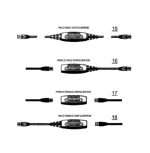
To provide customizability, the wiring standard selector switch (1) may be
provided with different configurations of an input connector (10) paired with
output
connector (11), some of which are shown in Figure 6. The different
combinations may
be, a male plug input connector paired with a male plug output connector (15),
a
female socket input connector paired with a male plug output connector (16), a
female
socket input connector paired with a female socket output connector (17), a
male plug
input connector paired with a female socket output connector (18). The
configurations
containing the female socket connectors allow the Network Technician, or the
like, to
selectively use pre-made network cables to be used in conjunction with the
wiring
standard selector switch (1).
Figure 7 presents a set of tables that correspond to different wiring
standards.
For each wiring standard, the table defines the paired electrical connection
between
each of the set of input contacts (7) and the set of output contacts (8).
Cam systems are commonly known in the art, and are not specific to the
present invention. Thus it will be known to one skilled in the art how to
integrate such
devices with the selector switch enclosure described herein.
Electrical contacts are commonly known in the art, and are not specific to the
present invention. Thus it will be known to one skilled in the art how to
integrate such
devices with the wiring standard printed circuit (9) described herein.
9
CA 02683182 2014-01-16
Network cables are commonly known in the art, and are not specific to the
present invention. Thus it will be known to one skilled in the art how to
integrate such
devices with the wiring standard selector switch described herein.
Printed circuits boards are commonly known in the art, and are not specific to
the invention. Thus, it will be known to one skilled in the art how to design
and
integrate such a device together with the wiring standard selector switch (1)
described
herein.
While the invention has been particularly shown and described with reference
to exemplary embodiments thereof, the scope of the claims should not be
limited by
the preferred embodiments set forth in the examples, but should be given the
broadest
interpretation consistent with the description as a whole.