Note: Descriptions are shown in the official language in which they were submitted.
CA 02683257 2009-10-05
WO 2008/127998 PCT/US2008/059953
INO-1005-PC
ANIMAL HUSBANDRY DRAWER CAGING
Field of the Invention
The invention pertains to the field of animal husbandry and to animal
containment.
Related Applications
This application claims priority under 35 U.S.C. section 119(e) from U.S.
Provisional
Patent Application Ser. No. 60/911,271, filed April 11, 2007, naming Dee L.
Conger,
Thomas M. Perazzo, Francesca McGuffie, and Matthew D. d'Artenay as inventors,
titled
"Animal Husbandry Drawer Caging Systems and Components" and identified by
attorney
docket number INO-1005-PV, and from U.S. Provisional Patent Application Ser.
No.
60/979,721, filed October 12, 2007, naming Dee L. Conger and Thomas M. Perazzo
as
inventors, titled "Animal Husbandry Drawer Caging" and identified by attorney
docket
number INO-1005-PV2, both of which are incorporated by reference herein in
their
entirety.
This application is related to U.S. Provisional Patent Application Nos.
60/635,756,
60/690,811 and 60/717,826 filed on 13 December 2004, 14 June 2005 and 16
September
2005, respectively, entitled "Animal Containment Systems And Components,"
naming
Thomas Perazzo and Dee Conger as inventors, and designated by attorney docket
nos.
INO-1001-PV, INO-1001-PV2 and INO-1001-PV3. This application is also related
to U.S.
Provisional Patent Application Nos. 60/734,229 and 60/734,189, each filed on 7
November
2005, entitled "Containment Systems And Components For Animal Husbandry,"
naming
Thomas Perazzo and Dee Conger as inventors, and designated by attorney docket
nos.
INO-1001-PV4 and INO-1001-PV5, respectively. This application is also related
to U.S.
Provisional Patent Application No. 60/804,554 filed on 12 June 2006, entitled
"Containment Systems And Components For Animal Husbandry," naming Dee Conger
et
al. as inventors, and designated by attorney docket no. INO-1001-PV6. This
application is
1
CA 02683257 2009-10-05
WO 2008/127998 PCT/US2008/059953
INO-1005-PC
also related to U.S. Provisional Patent Application Nos. 60/822,755 and
60/822,914 filed
on 17 August 2006 and 18 August 2006, entitled "Containment Systems And
Components
For Animal Husbandry," naming Dee Conger et al. as inventors, and designated
by
attorney docket nos. INO-1001-PV7 and INO-1001-PV8, respectively. This
application is
also related to U.S. Patent Application No. 11/300,664 filed on 13 December
2005,
International Patent Application No. PCT/US2005/044977 filed on 13 December
2005,
U.S. Patent Application No. 11/423,949 filed on June 13, 2006, and
International Patent
Application No. PCT/US2006/023038, each entitled "Containment Systems And
Components For Animal Husbandry," each naming Dee Conger et al. as inventors,
and
designated by attorney docket nos. INO-1001-UT, INO-1001-PC, INO-1001-UT2 and
INO-
1001-PC2, respectively, International Patent Application No. PCT/US2007/018255
, filed
August 17, 2007, naming Dee L. Conger, Thomas M. Perazzo, Matthew D. d'Artenay
and
Francesca McGuffie as inventors, entitled "Containment Systems and Components
for
Animal Husbandry" and assigned attorney docket no. INO-1001-PC3. Each of the
foregoing patent applications is incorporated herein by reference in its
entirety.
Background
Animal containment systems are utilized in a variety of applications, such as
for animal
transportation, breeding and maintenance. Animals contained in the systems
often are
laboratory animals such as rodents, and such animals often are contained in a
vivarium.
Containment systems may include animal cages in which the animals are housed
and a
rack unit onto which cages are mounted. Animals contained in such systems emit
several
gaseous and particulate contaminates that are health risks to housed animals
and human
personnel maintaining the systems. Generally, permanent or multiple-use cages
are
designed for multiple uses, which requires they are washed and sterilized
about every
week for two years or more in an animal containment facility, for example,
especially in a
facility practicing Good Laboratory Procedures (GLPs). Multiple-use cages
generally are
heavy and have relatively thick walls and components often are constructed
from resilient
materials that can withstand multiple washes and sterilizations. Such cages
may be
disposed in a rack that holds multiple cages in order to house the animals
more efficiently,
2
CA 02683257 2009-10-05
WO 2008/127998 PCT/US2008/059953
INO-1005-PC
however, it may be inconvenient to remove the cages from such rack in order to
perform
cleaning and other maintenance work.
Due to these aspects of typical multiple-use animal containment systems, a
significant
portion of animal containment resources are required for washing and
sterilizing multiple-
use components. Multiple-use cage designs also can present disadvantages with
respect
to contamination, such as requiring contaminated air filter handling or
exposure of cage
components to the environment when a cage impacts a surface (e.g., a cage is
dropped by
a user or falls from an elevation), for example, which bear especially on
handling of
animals in higher biosafety level animal facilities.
As such, what has been needed are animal containment cages and systems that
eliminate the need for regular washing of cages, provide a safe and healthy
environment
for contained animals and optionally provide an efficient means for housing a
large number
of animals in a limited space. What has also been needed are such animal
containment
cages and systems that allow for easy access to the contained animals by
laboratory
personnel or anyone else that may need to access contained animals.
Summary
Some embodiments of a disposable drawer containment cage assembly for animal
containment include a base having four sides and a bottom portion having a
substantially
continuous rectangular structure and having lid contact members disposed
substantially
parallel to each other at an upper rim on opposite sides of the base. The
assembly also
includes a lid having a generally planar configuration with channel members
which are
disposed parallel to each other at opposite sides of the lid and which are
configured to
slidingly engage the lid contact members of the base while maintaining the
base vertically
secured to the lid.
Some embodiments of a method of accessing an interior volume of a disposable
drawer containment cage assembly includes providing a drawer containment cage
assembly. The cage assembly includes a base having four sides and a bottom
portion
having a continuous rectangular structure and having lid contact members
disposed
substantially parallel to each other at an upper rim on opposite sides of the
base. The
3
CA 02683257 2009-10-05
WO 2008/127998 PCT/US2008/059953
INO-1005-PC
cage assembly also includes a lid having a generally planar configuration with
channel
members which are disposed parallel to each other at opposite sides of the lid
and which
are configured to slidingly engage the lid contact members of the base while
maintaining
the base vertically secured to the lid. Once provided, the base is slid
outward relative to
the lid so as to create an opening between the front edge of the lid and front
edge of the
base with the base still vertically secured to the lid. Thereafter, the
interior volume of the
cage assembly is accessed through the opening.
Some embodiments of a rack system for mounting a plurality of drawer
containment
cage assemblies includes a frame assembly having a wall portion and at least
one shelf
assembly secured to the wall portion and including a shelf. The shelf assembly
also
includes at least one carriage assembly which is disposed in functional
arrangement with
the at least one shelf. The carriage assembly includes a carriage body having
a nozzle in
communication with a ventilation system and configured to releasably engage a
receptacle
of a containment cage disposed on the shelf assembly, a spring bias member
configured
to exert a spring bias on the carriage body towards a receptacle and a support
frame
system with the carriage body mounted to the support frame system so as to
allow limited
transverse movement of the carriage body and nozzle relative to the shelf and
support
structure.
Some embodiments of a disposable drawer containment cage assembly include a
base having four sides and a bottom portion having a substantially continuous
rectangular
structure. The base also has lid contact members disposed substantially
parallel to each
other at an upper rim on opposite sides of the base. The cage assembly also
includes a
lid having a generally planar configuration with channel members which are
disposed
parallel to each other at opposite sides of the lid and which are configured
to slidingly
engage the lid contact members of the base while maintaining the base
vertically secured
to the lid. A perforated food tray including a high strength material
resistant to chewing by
contained animals may be disposed under the first ventilation receptacle when
the cage is
in a closed state such that the food tray prevents access to the first
ventilation receptacle
with the cage in a closed state. A perforated water bottle tray including a
high strength
material resistant to chewing by contained animals may be disposed under the
second
4
CA 02683257 2009-10-05
WO 2008/127998 PCT/US2008/059953
INO-1005-PC
ventilation receptacle when the cage is in a closed state such that the water
bottle tray
prevents access to the second ventilation receptacle with the cage in a closed
state.
These features of embodiments will become more apparent from the following
detailed description when taken in conjunction with the accompanying exemplary
drawings.
Brief Description of the Drawings
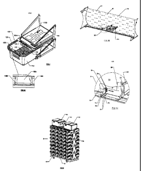
FIG. 1 is a side view of a containment cage assembly having a base which is
configured to slide open relative to the lid shown in a closed state and
disposed in a shelf
of a rack system.
FIG. 2 shows the cage assembly of FIG. 1 in an open state.
FIG. 3 is a perspective view of the containment cage assembly of FIG. 2 in an
open
state.
FIG. 3A is an enlarged view of a front edge of the embodiment of FIG. 3.
FIG. 3B is a perspective view of an embodiment of a rack module.
FIG. 3C is an enlarged view of the encircled portion of FIG. 3B.
FIG. 3D is a perspective view of an embodiment of a rack system.
FIG. 4 is a top view of the containment cage assembly of FIG. 2 in an open
state
without the shelf of the rack system shown.
FIG. 5 is a side view in partial section of the containment cage assembly of
FIG. 1.
FIG. 6 is an enlarged view in section of a front edge of the containment cage
of FIG.
5.
FIG. 7 is an enlarged view in section of the rear edge of the containment cage
of FIG.
5.
FIG. 8 is a perspective view of the containment cage assembly in a closed
state.
FIG. 9 is an elevation view of a lid of the containment cage embodiment.
FIG. 10 is a top view of the lid of the containment cage.
FIG. 11 is an exploded view of the containment cage assembly embodiment of
FIG.
1.
5
CA 02683257 2009-10-05
WO 2008/127998 PCT/US2008/059953
INO-1005-PC
FIG. 12 is a perspective view of a water tray embodiment of the containment
cage
assembly of FIG 1.
FIG. 13 is a transverse cross sectional view of the containment cage assembly
with
the section taken through the water bottle assembly and water bottle tray.
FIG. 14 is a perspective view of a food tray embodiment of the containment
cage
assembly of FIG 1.
FIG. 15 is a transverse cross sectional view of the containment cage assembly
with
the section taken through the food tray.
FIG. 16 is a perspective view of a shelf of a rack system from underneath the
shelf.
FIG. 17 is an enlarged view of a carriage assembly of the shelf and rack
system of
FIG. 16.
FIG. 18 is a bottom view of the shelf of the rack system.
FIG. 19 is an enlarged view of a carriage assembly of the shelf and rack
system of
FIG. 18.
FIG. 20 is a side view in section of a carriage assembly of the rack system.
FIG. 21 is a perspective view of a containment cage assembly having a lid and
upper
rim of a base that are configured to couple together in a snap fit.
FIG. 22 is an exploded view of the containment cage assembly of FIG. 21.
FIG. 23 is an elevation view of an embodiment of a containment cage assembly
having a base which is configured to slide open relative to the lid shown in a
closed state
and disposed in a shelf of a rack system.
FIG. 24 shows the cage assembly of FIG. 23 in an open state.
FIG. 25 is a perspective view of the containment cage assembly of FIG. 23 in
an
open state.
FIG. 26 is a top view of the containment cage assembly of FIG. 25 in an open
state
without the shelf of the rack system shown.
FIG. 27 is an elevation view in partial section of the containment cage
assembly of
FIG. 23.
FIG. 28 is an enlarged view in section of a front edge of the containment cage
of FIG.
27.
6
CA 02683257 2009-10-05
WO 2008/127998 PCT/US2008/059953
INO-1005-PC
FIG. 29 is an enlarged view in section of the rear edge of the containment
cage of
FIG. 27.
Detailed Description
Provided herein are animal containment systems that allow easy and convenient
access to contained animals and may include disposable, single-use components,
which
do not require washing and sterilization by laboratory personnel. The animal
containment
systems and components may be used for transportation of animals and may be
used for
containment of animals for research and breeding, for example. Cages of such
systems
often include relatively thin walls constructed from a polymer. Features of
cage
embodiments discussed herein may substantially reduce or prevent the
possibility that
contained animals will damage the relatively thin polymeric material (e.g.,
gnawing
damage). The low weight and relative flexibility of single-use cages, as
compared to
thicker, rigid multiple-use cages, provide for cages less prone to breakage or
disassembly
upon impact. These features reduce the likelihood that cage contents (e.g.,
animals,
animal contaminants and any harmful substances in the cage) are exposed to the
outside
environment upon impact (e.g., cage bases and lids remain sealed after
impact).
Some cage embodiments and associated components also may be efficiently
nested,
thereby advantageously reducing required storage space. Ventilated system
embodiments provided herein may be configured to efficiently exchange air in
cages and
efficiently maintain temperature within cages. Such ventilated systems may be
operated at
relatively high air pressures and without adjustable valves, providing for
airflow and air
pressure uniformity and efficient airflow control across a range of air
pressures. Also
provided are animal containment systems that comprise modular components,
often
components that are readily disassembled. In some embodiments, rack units
include one
or more attachable and detachable rack modules that are readily disassembled
for
washing of the rack modules. These and other features of the components
disclosed
herein can reduce the amount of resources required for animal containment, can
enhance
quality of care afforded to the housed animals, and can minimize health risks
to human
personnel who care for or study the contained animals.
7
CA 02683257 2009-10-05
WO 2008/127998 PCT/US2008/059953
INO-1005-PC
Some animal containment cage embodiments may include a containment cage base
member, a cover or lid member, and an optional insertion member or device. An
animal
cage base sometimes is provided separately from a lid, the lid often may be
attached to
the cage base and the lid may be readily detachable from the base. An animal,
such as a
rodent, and/or optional insertion member may be placed in a cage base before a
lid is
attached. A variety of animals may be contained within cage embodiments
described
herein. Rodents often are contained within such units, including but not
limited to mice,
rats, hamsters, gerbils, guinea pigs, chinchillas and rabbits. The animal can
be transgenic,
inbred, immunodeficient, lack one or more functional genes (e.g., knock-out
animal),
and/or can include one or more xenografts. Examples of immunodeficient mice
include
nude mice and severe combined immune deficiency (SCID) mice. Cells from
cultured cell
lines, cultured primary cells or directly from another animal or tissue (e.g.,
biopsy) may be
utilized for xenografts (e.g., cancer cells from a human). The animals
contained in cages
and systems described herein can be utilized in a variety of manners,
including but not
limited to studying cancer and other diseases, assessing parameters of
potential drugs
(e.g., toxicity, efficacy, maximum tolerated doses, effective doses and other
pharmacokinetic parameters), producing and isolating antibodies and producing
and
isolating cells useful for preparing hybridomas, for example.
Cage base embodiments may be of any geometry suitable for housing animals,
such
as cylindrical, substantially cylindrical, conical, rectangular, square,
cubic, rhomboid and
the like, for example. Cage base embodiments may include a bottom member that
supports a plurality of sides or sidewall members (e.g., four sidewall
members). One
sidewall member often is referred to as the "front sidewall member" and the
opposite
sidewall member often is referred to as the "rear sidewall member." Opposing
sidewall
members sometimes are parallel, substantially parallel, not parallel,
rhomboid,
substantially rhomboid or a combination thereof. In some embodiments, opposing
sidewalls are not parallel, and are not vertical with respect to the bottom.
In such
embodiments, a sidewall, and sometimes all sidewalls, are at a non-90 degree
angle with
respect to the bottom, such as an angle between about 91 degrees and about 105
degrees, an angle of about 92 degrees to about 98 degrees or an angle of about
95
8
CA 02683257 2009-10-05
WO 2008/127998 PCT/US2008/059953
INO-1005-PC
degrees, for example. Such angled sidewall configurations (with respect to the
bottom)
can promote cage base nesting (described in greater detail hereafter).
Each edge junction or corner junction of a wall or walls and/or the bottom may
have a
geometry convenient for manufacture and use, such as a sharp edge, smooth edge
or
rounded edge. It has been determined that certain corner and edge geometries
in animal
containment components reduce or eliminate the possibility of damage caused by
animal
residents (e.g., gnawing damage by rodents). This resistance to damage caused
by
contained animals may be especially applicable to single-use containment
components
having thin polymer walls (e.g., about 0.01 inches to about 0.08 inches).
Damage resistant
edge and corner orientations have been determined based upon a combination of
(i) angle
of edge or corner surfaces (in degrees) and (ii) edge or corner radius (in
inches). The
angle alpha between two surfaces is measured from the side of the surfaces on
which an
animal resides. When alpha is less than 180 degrees, the edge or corner
minimum radius
may be zero. When alpha is between 180 degrees and 360 degrees, a minimum
radius
can be determined by the following equation:
minimum radius = 0.25/(tan((pi/360)(360-alpha))).
For example, minimum edge and corner radii of 0.02, 0.04, 0.07, 0.09, 0.12,
0.14, 0.18,
0.21, 0.25, 0.30, 0.36, 0.43, 0.54, 0.69, 0.93, 1.42, 2.86 and 5.73 inches
often are
incorporated when the corresponding angle alpha is 190, 200, 210, 220, 230,
240, 250,
260, 270, 280, 290, 300, 310, 320, 330, 340, 350 and 355 degrees,
respectively, in
accordance with this relation. Thus, provided are edge and corner
angle/minimum radius
combinations in accordance with the above relation.
Cage base embodiments may include rounded junctions of a suitable radius,
which can
minimize damage caused by gnawing or clawing of housed animals, for example.
Thus, in
some embodiments, bottom corners, each formed at the junction of a bottom and
two
sidewalls, often are not sharp corners and often are smooth corners defined by
a radius.
Each corner in some embodiments may be effectively split into multiple edges
which may
improve crumple resistance to impact. Crumple resistance to impact provides
benefits of
maintaining nesting efficiency, reducing potential damage caused by animal
gnawing (e.g.,
impact can crumple a corner and introduce a sharp edge on which an animal may
gnaw),
and maintaining cage integrity upon impact (e.g., not exposing the cage
interior to the
9
CA 02683257 2009-10-05
WO 2008/127998 PCT/US2008/059953
INO-1005-PC
outside environment). In certain embodiments, a corner may be effectively
split into 10, 9,
8, 7, 6, 5, 4 3 or 2 corners, each often defined by a radius.
A top edge of one or more sidewall members often is contiguous with a flange
or rim
portion that extends, often vertically, from the outer surface of the sidewall
member. The
flange sometimes forms a continuous surface around the top perimeter of the
cage and its
surface often is horizontal when a bottom member of the cage rests on a
horizontal
surface. The flange may be any suitable width, sometimes about 0.03 inches to
about 1
inch. The flange can increase cage base rigidity and sometimes is configured
to mate with
a portion of a lid member, described further herein. In some embodiments, the
flange
includes an optional downward extending lip member, which sometimes mates with
a
corresponding member of a lid to form a detachable seal. The profile of the
lip member of
the base is of any shape to allow a fit with a corresponding structure on the
lid, where the
profile sometimes is curved, and sometimes is S-shaped, V-shaped or J-shaped.
The lip
member and/or flange member of the cage base sometimes are shaped to deflect
when
mated with a lid member to form a seal between the cage base and the lid. A
seal
between cage base embodiments and lid embodiments, which may be partial, may
be of
any convenient or useful type, including but not limited to an adhesive seal,
compression fit
or interference fit, for example. Some cage embodiments do not require or
include a seal
between the cage base and lid.
A cage base sometimes includes one or more indents in a sidewall member that
extends towards the interior of the cage base. One, two, three, four or more
sidewalls
sometimes include one or more indents, which can increase sidewall rigidity.
Sidewall
integrity enhancement can provide an advantage of increasing impact resistance
to
crumpling, advantages of which are described above. The depressed surface area
of an
indent can be trapezoidal or rectangular. The depressed distance of the indent
vertical
from a sidewall from which the indent extends often is continuous from the top
of the
indent to the bottom (e.g., the face is parallel to the side wall from which
the indent is
extended), and may be greater at the top of the indent, sometimes tapering
from the top
portion of the indent to the bottom portion. Such configurations allow for
nesting of cage
bases when they are not housing an animal, as described hereafter.
CA 02683257 2009-10-05
WO 2008/127998 PCT/US2008/059953
INO-1005-PC
A cage base may include one or more mounts located on an outside surface of a
sidewall member or bottom member, which may be referred to as "outer support
members"
or "outer guide members," which allow for convenient mounting of the cage into
a rack unit.
The outer support members or outer guide members are of any configuration
allowing for
mounting of the cage base into a rack unit member or shelf, and sometimes mate
with or
are supported by corresponding members in a rack unit embodiment. In some
embodiments, a flange member contiguous with the top of one or more sidewall
members
serves as a guide member and/or support member.
In certain embodiments, a guide member and/or support member is a flange,
projection, rib or groove located on the exterior surface of a bottom member
of a base
and/or one or both cage sidewall members (e.g., sidewall member adjacent to
the front
sidewall and rear sidewall), and often may be parallel with the top edges of
the sidewall
members. Such guide members and support members sometimes extend from the
front
edge of a sidewall member, sometimes extend to the rear edge of a sidewall
member,
sometimes extend from a point in a sidewall member a distance from the front
edge, and
sometimes extend to a point in a sidewall member a distance from the rear
edge. Such
members sometimes are oriented in the middle half of the vertical length of a
sidewall
member, and sometimes are oriented in the middle of the vertical length. In
some
embodiments, guides are low profile, and sometimes are grooves or depressions,
that do
not substantially interfere with nesting of cage bases.
Some cage base embodiments may be manufactured from any material suitable for
housing an animal, such as a small rodent, for a time period of about one week
or greater.
The material may be rigid, and often is a semi-rigid or flexible material. The
cage base
sometimes is constructed entirely, or in part, from a translucent or
transparent material.
Examples of materials that may be utilized for manufacture of any of the a
cage base or lid
embodiments discussed herein include, but are not limited to, polypropylene
(PE), high-
density polyethylene, low-density polyethylene, polyethylene teraphthalate
(PET), polyvinyl
chloride (PVC), polyethylenefluoroethylene (PEFE), polystyrene (PS), high-
density
polystryrene, acrylnitrile butadiene styrene copolymers and the like. In
certain
embodiments, a cage is constructed from PET or PS (e.g., high density PS).
11
CA 02683257 2009-10-05
WO 2008/127998 PCT/US2008/059953
INO-1005-PC
Sidewall members and bottom members of cage base embodiments may be of any
thickness for substantially maintaining cage integrity for about one, two,
three or four or
more weeks of animal containment, and the thickness sometimes is about 0.01
inches to
about 0.08 inches. The sidewalls often are of substantially uniform thickness.
A cage
base often is manufactured as a single unit and by any convenient process,
sometimes in
an injection molding, thermoforming or vacuum forming process, for example. A
cage
base often is packaged for shipment, sometimes as a single unit and sometimes
with other
like units (e.g., as a nested set described hereafter). A cage base sometimes
is washed
and/or sterilized (e.g., U.V. irradiation, gamma irradiation) prior to
packaging. Cage bases
may be packaged in any material, including but not limited to materials
containing
polystyrene, polyvinyl chloride, low-density polyethylene and the like.
Some embodiments of a cage base floor may be about 60 square inches to about
90
square inches, and sometimes about 75 square inches, for some embodiments. The
height of such cages sometimes is about 4 inches to about 6 inches and
sometimes about
5 inches. In a specific embodiment, wall junction radii are about 1 inch, and
sometimes
1.06 inches. In some embodiments, the cage is constructed from PET and weighs
about
110 grams to about 150 grams, and sometimes is about 130 grams (e.g., 130.4
grams).
For rat cage bases, the cage floor sometimes is about 130 square inches to
about 150
square inches, and sometimes is about 140 square inches. The height of such
cages
sometimes is about 5 inches to about 9 inches, and sometimes is about 7
inches.
A cover or lid may be provided separately from a cage base, often reversibly
mates
with a cage base, sometimes in sealing attachment, and may be of any suitable
geometry
allowing for attachment to base embodiments, including sliding attachment.
Some lid
embodiments may include one or more members that directly mate with and seal
with one
or more members of a base; sometimes has no side wall members; and sometimes
is
planar or substantially planar. Some lid embodiments may be constructed from
any
material that allows for animal containment for about one week or greater.
Materials for
constructing a lid sometimes are selected to allow for sealing or partial
sealing attachment
to a cage base. Examples of materials from which lid embodiments may be
constructed
include those described above for cage base embodiments. Sometimes the lid and
base
12
CA 02683257 2009-10-05
WO 2008/127998 PCT/US2008/059953
INO-1005-PC
are constructed from the same material and sometimes are of a similar or the
same
thickness as a thickness of a corresponding base.
Some lid embodiments may be flexible or semi-rigid and include a substantially
planar
region and a flange region. The substantially planar region may include one or
more
components described herein. A flange region of lid embodiments sometimes is
embossed, may be raised and may includes a region that extends downwards as a
lip
(referred to herein as a "lip"). A flange and optional lip region may extend
continuously
around the perimeter of lid embodiments. The profile of the flange and
optional lip often
correspond to a flange and optional lip on a cage base, and may allow the lid
to seal or
partially seal with some base embodiments. The flange and optional lip may
include any
suitable shape to fit with corresponding base embodiments, and sometimes are S-
shaped,
V-shaped, J-shaped and U-shaped, upwards or inverted, for example.
Some lid embodiments may include one or more of a continuously solid surface,
an
imperforate surface region, and/or a perforated surface region (e.g., a region
containing air
holes or a grid structure). A lid member sometimes includes, sometimes within
a
substantially planar region, an aperture, a groove, a channel, a depressed or
indented
region, a bossed region, a rib (e.g., an embossed rib or solid rib), and
sometimes a
combination of the foregoing. Such a structure or structures may be located
near a
heavier structure in the lid, such as around or near a water supply receptacle
or a
connector that receives a corresponding non-lid connector. A lid member
sometimes
includes other components, such as a filter, a baffle, a feeding structure,
and/or a watering
structure, holders of the foregoing, and combinations of the forgoing, where
each structure
is integral or provided as a component separate from the lid member. Edges or
corners in
a lid may be rounded or otherwise defined by a radius and/or angle as
described herein for
cage base embodiments. A lid in certain embodiments may be rigid. A lid member
may
comprise a combination of a flexible region with a rigid or semi-rigid region,
the rigid or
semi-rigid region sometimes acting as a frame that allows a lid to be handled
efficiently
and conveniently when securing it to a cage base, for example. Lid
embodiments, or a
portion or portions thereof, may be translucent or transparent.
Lid embodiments may sometimes include one or more air filters. Such air
filters often
are configured to filter components (e.g., particulates) in air exiting an
interior volume of a
13
CA 02683257 2009-10-05
WO 2008/127998 PCT/US2008/059953
INO-1005-PC
cage. Some filter embodiments may be composed of any filter material useful
for housing
animals, including but not limited to spunbonded polyester, pressed pulp
(depth filter), a
Reemay filter (e.g., Reemay 2024), high-efficiency particulate air (HEPA)
filter and the like
(e.g., U.S. Patent No. 6,571,738). Filter embodiments may be configured to
exclude or
otherwise filter out particles which are about 1 micron to about 5 microns in
size, more
specifically, about 0.3 microns to about 1 micron in size. The filter often is
in effective
connection with a portion of the surface area of a lid member, and often only
a portion or
fraction of the surface area of the lid member. In some embodiments, the
filter may be in
effective connection with 80% or less, 70% or less, 60% or less, 50% or less,
40% or less,
30% or less, 25% or less, or 20% or less of the lid member surface area.
Filter
embodiments sometimes are integrated with the lid (e.g., the filter is not
reversibly
mounted to the lid member), and may be provided separately from the lid. When
provided
separately from the lid, a filter often is placed in effective connection with
a portion of the
lid, often a perforated portion of the lid (e.g., a portion having air
apertures or a grid
structure).
A filter may be affixed to a lid in any suitable manner, often by reversible
attachment
and/or sealing attachment, and in some embodiments, filter embodiments may
include an
adhesive, sometimes on the outer perimeter of the filter, sometimes across the
entire
surface area of the filter, and often on one side of the filter. Where the
filter includes an
adhesive, it sometimes is provided with a peel-off backing that exposes the
adhesive, and
the adhesive often allows for reversible adhesion (e.g., the filter can be
affixed, removed or
partially peeled back from the lid, and then affixed again, which can be
repeated multiple
times). Filter embodiments may be secured to a lid by a manufacturer of the
lid, and/or
may be attached/detached by a user. In some embodiments, filter embodiments
may be in
connection with a flexible film, the latter of which is coated on a surface
(e.g., the entire
surface or a portion of the surface) with an adhesive. When an adhesive is
utilized, it often
is not substantially toxic to animals housed in the cage and sometimes is a
food grade
adhesive. The filter and/or film often may be disposed adjacent to or in
effective
connection with one or more apertures of the lid.
In certain embodiments, a filter may be sandwiched between the lid and a
holding
member attached to the lid. The holding member often includes one or more
apertures
14
CA 02683257 2009-10-05
WO 2008/127998 PCT/US2008/059953
INO-1005-PC
through which air may flow, and the holding member often is sealingly attached
to the lid
(e.g., attached by an adhesive). In such embodiments, a substantial surface
area of the
filter often is not in direct contact with the holding member, which may
provide an
advantage of reducing potential gnawing damage caused by a contained animal
(such a
holding member also is referred to herein as a "filter shield"). Standing an
air filter away
from surfaces of the lid and optional filter shield(s) provides certain
advantages, such as
permitting efficient airflow and protecting filter material from possible
damage caused by
contained animals (e.g., animals cannot effectively contact the filter). For
example, some
filter embodiments may have a pore size of about 0.5 microns and there may be
approximately 1000 pores per inch. The corresponding percentage of open area
for this
type of filter may be about 2%.
A relatively large filter surface may be utilized in some embodiments to
permit airflow
through the filter without significant restriction or pressure drop. Filter
dimensions in the lid
sometimes are about six (6) inches by about two (2) inches. The resulting area
available
to airflow for a filter of these dimensions may be about 12 square inches
multiplied by 2%.
The area available to airflow would be significantly limited by exhaust
apertures in the lid if
the filter paper were in direct contact with the lid (e.g., the area available
to flow is that of
the area of the apertures, which can be (the square of 0.125/4 multiplied by
27 holes
multiplied by 2%). Thus, standing a filter away from apertures in the lid and
optional filter
shield(s) can significantly enhance airflow by allowing the entire filter
paper to breathe.
Characteristics of cages provided herein may contain cage components when the
cages are exposed to physical impact. For example, combinations of (i) sliding
attachment
of a cage base to a lid, (ii) light weight of the cage base and lid resulting
from thin walls,
(iii) flexibility of the semi-rigid base and lid, and (iv) base corner
geometry (e.g., effectively
split into more than one corner), may be configured to reduce the possibility
that cage
contents (e.g., animals, animal waste and cage additives) are exposed to the
outside
environment as compared to reusable, rigid cages. In the event a cage is
exposed to
impact (e.g., dropped or falls to a floor from an elevated position) these
features may
protect contained animals from the exterior environment and protect personnel
from cage
contents. These features may be desirable for application in higher biosafety
level
environments, for example.
CA 02683257 2009-10-05
WO 2008/127998 PCT/US2008/059953
INO-1005-PC
Lid embodiments may sometimes include a substance that scavenges emissions
from
an animal in the cage. Emissions sometimes are gaseous or particulate
compositions,
such as those resulting from exhalation (e.g., water vapor, carbon dioxide),
urination and
defecation (e.g., ammonia, microbes), and exfoliation (e.g., dander, hair
follicles, allergens,
fomites, microbes (e.g., bacteria, fungi and viruses)), for example. The
scavenging
substance sometimes is a catalyst or is utilized in combination with a
catalyst that breaks
down an emission from an animal into innocuous substances (e.g., biocatalyst).
A
scavenging substance sometimes is included in a filter or is located adjacent
to a filter, and
sometimes is located in another portion of a cage (e.g., on a floor and/or
below a sub-
floor). Any scavenging substance suitable for use with animals can be used,
such as
charcoal or other form of carbon.
Lid embodiments sometimes include a delivery component for delivering a
consumable
element to a housed animal, such as air, water or food. The delivery component
sometimes is integral with the lid, sometimes the lid is in contact with a
separate delivery
component (e.g., a surface of the lid is in contact with a flange member of a
food trough),
sometimes the lid comprises a holder or receptacle for the delivery component,
and
sometimes the lid includes an aperture adapted to receive the delivery
component. In
some embodiments the lid includes one or more connectors adapted to receive an
air
supply or air exhaust component or water supply component (e.g., a nozzle or
nozzle
receptacle). A connector can be of any geometry to receive a corresponding
connector
from an air supply, air exhaust or water supply component. The cage lid
connector often
mates with the air supply, air exhaust or water supply connector by a sealing
attachment,
and often by a reversible connection, and the connectors are of any suitable
type. For
example, the connection may be defined by cylindrical, square, rectangular or
conical side
geometry, and flat, rounded, tip or point geometry for the top or bottom, for
example. The
connecting member in the lid may be a protrusion or a void (e.g., concave or
convex,
respectively) that receives a corresponding mating void or protrusion,
respectively.
In some embodiments the connector structure in the lid may be a void that
includes two
apertures, a larger aperture and a smaller aperture, where the larger aperture
is spaced
above the smaller aperture. In such embodiments, the mating nozzle connector
may be
seated, often reversibly, in the void, thereby forming a substantially air-
tight seal. In some
16
CA 02683257 2009-10-05
WO 2008/127998 PCT/US2008/059953
INO-1005-PC
embodiments the connector structure in the lid comprises a protrusion having
an aperture,
where the aperture is at the apex of the protrusion. In such embodiments, a
void in the
mating nozzle connector may be configured to fit over the protrusion in the
lid, often
reversibly, and forms a substantially air-tight seal. Connection geometry in
the latter
described embodiments can provide advantages of (a) expanding air exiting an
air supply
connector along inner walls of the lid connector and other lid and cage
surfaces, which
expansion cools air in the cage and compensates for thermal load of a
contained animal,
and (b) substantially reducing or preventing the possibility of damage caused
by contained
animals (e.g., gnawing, clawing).
Some embodiments of a containment cage have a conical receptacle in the lid,
and the
connection member may be conical concave in certain embodiments. The nozzle
connector of the air supply component may be seated in the lid by hand or by
any other
method, and connection may be a gravity fit, pressure fit, screw fit, spring
bias
engagement or another suitable fit. In some embodiments, the conical connector
is held in
a carriage that guides the connector into the lid. Such carriages sometimes
are connected
to a rack unit, often to a shelf thereon, embodiments of which are described
hereafter. The
conical void sometimes may be located in an embossed region of the lid, where
the top
surface of the embossed region sometimes is substantially elliptical. Where
the lid
comprises a flange, the height of the embossed region sometimes is equal to or
substantially equal to the highest point of the flange.
A connector, such as an air supply and/or air exhaust or water supply
connector,
sometimes is in contact with a channel. The channel is formed within the lid
in some
embodiments, and may be formed by raised corresponding raised portions on each
side of
the lid. The channel in some embodiments may be formed by the mating of (a) a
bossed
portion of the lid and (b) a corresponding bossed portion in a filter barrier
member. The
channel often includes one or more apertures on the side opposite the
connector, such
that air introduced through the connector may enter the cage. In embodiments
where the
channel is formed in part by a filter shield, the filter shield may include
one or more
apertures. In some embodiments, two or more apertures are distributed across
the length
of the channel, which can provide an advantage of distributing or exhausting
airflow across
the width of the cage, or a portion thereof. The channel may be of any
suitable shape for
17
CA 02683257 2009-10-05
WO 2008/127998 PCT/US2008/059953
INO-1005-PC
permitting airflow: the channel cross section may be circular, ovular, semi-
circular, semi-
ovular, rectangular, square, rhomboid or trapezoidal, for example, and the
length of the
channel may comprise or consist of a linear, circular, triangular,
rectangular, ellipsoid, arc,
sinusoidal or zig-zag geometry, for example. The length of the channel
sometimes is not
entirely linear and sometimes it is non-linear. The latter embodiments provide
an
advantage of reducing adherence of a filter to the lid or a filter barrier as
a filter surface
cannot depress as readily across a non-linear depression as a linear
depression.
Some cage embodiments provided herein allow for transverse cage airflow
designed to
minimize air recirculation and bypass, thereby providing efficient use of
airflow for air
exchange and temperature regulation. In some embodiments, provided is an
animal
containment cage including a lid and a base, where the lid may include an air
inlet and an
air exit, a baffle between the air inlet and air exit that extends downwards
into the interior
of the cage, and air flows downward from the inlet, through the cage interior
and out the
exhaust exit. In certain embodiments, air flows in a substantially U-shaped
pattern, and
sometimes the cage includes nesting material for an animal and air flows in
proximity to or
through the nesting material. The air inlet sometimes is at substantially one
end of the lid
and the air exhaust exit is at substantially the end of the lid. The air inlet
sometimes
includes an air supply connector, and the air exhaust exit sometimes includes
an array of
apertures and/or one or more air exhaust connectors. The baffle sometimes
extends from
one wall of the cage to the opposite wall, and sometimes is one or more
surfaces of a
feeding tray. The baffle often may be in effective sealing connection with two
walls of a
cage (e.g., a feeding trough resting on two cradles, one in each of two
opposing sidewalls)
to prevent or substantially reduce airflow around baffle sides and permit
airflow under the
baffle.
In some embodiments, a lid or base of a containment cage may be in connection
with
an airflow baffle. Airflow baffle embodiments often extend downwards from an
inner
surface of lid embodiments into a portion of the cage interior. A baffle often
may be
located between an air inlet aperture and an air exit aperture, thereby
directing airflow
around the baffle. Sides of baffle embodiments often are in close contact or
substantially
contacted with sidewalls of a cage base so that airflow is directed towards
the bottom of
the cage base and does not bypass the baffle along cage sidewalls. In some
18
CA 02683257 2009-10-05
WO 2008/127998 PCT/US2008/059953
INO-1005-PC
embodiments, a feed tray is configured such that a wall of the tray acts as a
baffle.
Directing airflow towards the bottom of the cage and then up through the top
of the lid may
be desirable for purging gaseous waste from bedding material located at the
cage bottom
and for reducing airflow required for maintaining the animals. In some
embodiments,
baffle embodiments may be formed by a food trough or tray in connection with a
lid and a
base that projects towards the bottom of the cage base. The food trough in
such
embodiments often is a member separate from the lid and the base and rests on
a cradle
(i.e., mount) formed in an indent within the cage base.
Some lid embodiments may include a water supply component. The lid sometimes
includes an integral water supply reservoir to which an emitter is connected
or integrated.
In some embodiments, the lid includes a water supply receptacle or holder into
which a
water supply that includes an optional emitter is seated, and in certain
embodiments, the
lid includes an aperture through which a water reservoir is fixed and/or
suspended. In
some embodiments, the lid is in connection with or comprises a feed supply
component,
often referred to herein as a "feeder," "food trough," or "food tray." The lid
sometimes
includes an integral food tray, and sometimes is in connection with a member
of a
separate food tray module when the lid is mated with a cage base. In some
embodiments,
the lid includes a food tray holder into which a food tray is seated, and in
certain
embodiments, the lid includes an aperture through which a food tray is fixed
and/or
suspended.
A lid member sometimes does not include an air exhaust connector and sometimes
does not include an air inlet connector. Accordingly, in some lid member
embodiments:
the lid member sometimes is rigid, semi-rigid, or flexible, or includes a
flexible region; the
lid member sometimes includes a flexible material and a semi-rigid material,
and
sometimes a filter; a filter in a lid often lids a portion of the surface area
of a lid member
and not the entire surface area of the lid member; the lid member sometimes
comprises a
continuously solid surface area and a filter, where the solid surface area is
rigid, semi-rigid,
flexible or a combination thereof; the lid member sometimes includes a
continuously solid
surface area and a filter, where the continuously solid surface area is
imperforate and not
a grid.
19
CA 02683257 2009-10-05
WO 2008/127998 PCT/US2008/059953
INO-1005-PC
Examples of cage members or components in addition to a cage base and lid
include
watering devices and feeding structures separate from a cage base or cage lid
or
integrated with the foregoing. These additional members are referred to herein
as "insert
or insertion members." A cage insert member sometimes may be placed in a cage
base or
cage lid before a lid is secured to the top of a base embodiments. In some
embodiments,
an insert member may be located near the top of a cage base in proximity to
the lid, such
as in food trough embodiments described herein. In some embodiments, an insert
member defines a top portion of a containment space for one or more animals
housed in
the cage. An insert member, such as a food tray, sometimes rests on or is
positioned by
one or more mounts or cradles extending from an inner surface of one or more
sidewall
members of a cage base.
In some embodiments, an insert is a substantially flat, planar member, where
the
surface of the insert is parallel to the surface of the cage base bottom
member. One or
more edges of the insert member often substantially mate, sometimes are
substantially
flush, sometimes are in close proximity, and sometimes are sealingly contacted
with the
inner surface of one or more sidewall members. In some embodiments, each edge
of the
insert substantially mates, is substantially flush, is in close proximity, or
is sealingly
contacted with the inner surface of each corresponding sidewall member. An
edge of an
insert member is of any thickness appropriate for the material from which it
is constructed
for housing an animal, and sometimes is about 0.010 inches to about 0.080
inches. An
insert member is constructed of any material suitable for containing an animal
using
materials and manufacturing process such as those described for manufacturing
cage
bases, for example.
An example of an insert member is a food tray. A food tray often includes a
bottom
integrated with four wall members, and optionally includes a lid adapted to
sealing attach
to the food tray. One or more sidewall members and/or the bottom, can include
one or
more openings or slots that expose food in the feeding structure to a housed
animal.
Opposing sidewalls sometimes are parallel, non-parallel, curved, elliptical or
rhomboid,
where two or more of the sidewall members may taper downwards to a bottom
member
having a surface area less than the surface area of the top opening or lid
member. Edge
and corner junctions between the sidewalls and bottom often are curved and
have a radius
CA 02683257 2009-10-05
WO 2008/127998 PCT/US2008/059953
INO-1005-PC
convenient for manufacture and animal feeding. A radius sometimes is selected
to
minimize abrasions caused by housed animals.
Some food tray embodiments may include a flange member surrounding the top
edge
of the food tray. In some embodiments, the food tray bottom is curved and not
flat, and in
certain embodiments the food tray is constructed from a plurality of
vertically arranged
tubular structures (e.g., wire). Some food tray embodiments may be constructed
of any
material suitable for feeding animals, examples of which include but are not
limited to: a
metal alloy, stainless steel, steel, nickel, nickel alloy, zinc, zinc alloy,
aluminum, a polymer,
polypropylene, high-density polyethylene, low-density polyethylene,
polyethylene
teraphthalate, polyvinyl chloride, polyethylenefluoroethylene, polystyrene,
high-density
polystyrene, acrylnitrile butadiene styrene copolymers and the like, and
combinations of
the foregoing. In some embodiments, a food tray may be constructed from a
polymer,
such as the same polymer from which the lid is manufactured, in certain
embodiments the
food tray is a metal alloy and in some embodiments the food tray may be a
combination of
a metal structure and a polymer frame or housing component.
In certain embodiments, the tray may be constructed from polyethylene
teraphthalate
or polystyrene (e.g., high-density polystyrene). In some embodiments, the food
tray, and
sometimes the cage and/or lid, may be constructed from a substantially hard
polymer.
Such polymers are known and measures of hardness include Rockwell (e.g.,
Rockwell M
or R), Brinell, Shore, Izod (e.g., Izod impact, notched), Charpy (e.g., Charpy
impact,
notched) and Vickers measures. Substantially hard polymers, as opposed to
softer
polymers, may reduce the possibility of gnawing damage caused by contained
animals
without increasing or substantially increasing material thickness.
Another example of an insert member is a water supply, which also may be
referred to
herein as a "reservoir." Water or another suitable hydrating liquid is emitted
to contained
animals via the water supply. The water supply or reservoir, and corresponding
reservoir
holder or aperture for receiving a reservoir in a cage component (e.g., lid),
is of any
geometry convenient for dispensing water. A reservoir may be a box-shaped
structure,
sometimes is a substantially cylindrical structure, and sometimes is a
substantially
cylindrical structure with gently tapered side walls (slightly conical) and a
chamfer. A
reservoir sometimes may be geometrically configured to reduce the potential of
abrasions
21
CA 02683257 2009-10-05
WO 2008/127998 PCT/US2008/059953
INO-1005-PC
caused by housed animals (e.g., reduce abrasions caused by animals gnawing on
the
watering structure), and in some embodiments, a reservoir comprises rounded
corners
(e.g., a rounded junction between a bottom edge and a sidewall member edge)
and/or
edges (e.g., rounded junction between two sidewall member edges).
Rounded corner radiuses are described herein. A reservoir sometimes is adapted
to
mate with a sealingly attachable lid or cap located in a convenient location
of the bottle
(e.g., the top or bottom), such as a screw-on lid or snap on lid, for example,
such that the
reservoir can be filled with water and then sealed with the lid. Accordingly,
a reservoir
often includes male or female threads adapted to receive threads from a screw-
on lid or a
fitting for a snap-on lid. A portion of the reservoir exposed to the inside of
a cage (e.g., the
bottom of the reservoir, cap or lid) often includes a small aperture that can
retain water by
surface tension until contacted by an animal.
A side wall region of the reservoir may be chamfered and sometimes can mate
with a
corresponding chamfer in a receptacle of the lid. Such a chamfer can function
as a key
that ensures alignment of the reservoir in the lid. A step in a radius of the
aperture also
may generate an interference fit with the reservoir receptacle, ensuring a
tight seal
between the reservoir and the lid and thereby reducing and substantially
preventing air
leakage. A reservoir may be constructed of any material suitable for
containing a fluid for
hydrating animals (e.g., water) including but not limited to: polypropylene,
high-density
polyethylene, low-density polyethylene, polyethylene teraphthalate, polyvinyl
chloride,
polyethylenefluoroethylene, acrylnitrile butadiene styrene copolymers,
cellulose, cellulose
lined with a polymer or metallic foil, and the like.
For embodiments in which a lid comprises a water reservoir holder, the
reservoir holder
sometimes is substantially cylindrical with slightly tapered sidewalls and a
chamber located
in the side and bottom. Such a geometry of the holder can key a similarly
shaped
reservoir, where the chamfers of the holder and the reservoir mate. Such
holders often
include an aperture, often in the chamfer region, adapted to receive an
emitter from the
reservoir, such that the emitter is accessible to a housed animal. Such
holders often are
adapted to receive a reservoir that includes a step in the radius such that
the top portion of
the reservoir has a larger diameter than the lower portion, which provides an
interference
fit with the inner wall of the holder and a substantially air tight fit.
22
CA 02683257 2009-10-05
WO 2008/127998 PCT/US2008/059953
INO-1005-PC
In some embodiments, an emitter contains a valve sometimes located in the
emitter
and sometimes located at the junction of the emitter and the reservoir. In
some
embodiments, the emitter contains no valve. A quick release coupling sometimes
connects the emitter to the reservoir. In certain embodiments, the emitter is
conical with
the larger cross sectional area connected to the reservoir and a small
aperture on the
opposite end accessible to a housed animal. In such embodiments, the aperture
is sized
to retain water in the reservoir by surface tension and to emit water when
contacted by a
housed animal. In certain embodiments, provided is a water bottle for use in
conjunction
with a lid, which comprises a cap having an aperture that retains water via
the inherent
surface tension of water within the cap face, the latter of which is defined
by a flat surface.
In the latter embodiments, the cape face is not conical and does not include a
projection.
Fluid supply embodiments may be configured to reduce the likelihood that an
animal
resident can damage the supply structure (e.g., gnawing damage). For example,
provided
herein are rodent containment cage bottles comprising three walls, a top, a
bottom an
aperture and a barrier in effective connection with the aperture, where: the
bottle may be
constructed from a polymer; two of the walls are about perpendicular (e.g., 85
degrees to
95 degrees or 90 degrees) and the third wall is curved; and the bottle may
retain fluid at
the aperture when inverted. The top, bottom and walls of the bottle generally
may form a
substantially semi-spherical structure, whereby the curved wall has a radius
of about 5
inches to about 9 inches (e.g., about 7 inches). Also, wall junctions and
corners often are
rounded, and the rounded junctions and corners sometimes are defined by a
radius of
about 0.25 inches or greater. When such water bottles are placed in
receptacles oriented
near or substantially in contact with one or more walls of a cage base, such
design
features minimize the likelihood an animal resident can access and damage the
bottle or
its receptacle.
In certain embodiments, the aperture is located in a cap in connection with
the bottle
(e.g., a screw cap). The bottle may contain a fluid such as water, and the
barrier often
may be a removable barrier such as an adhesive tab over the aperture. In some
embodiments, the barrier is inside the cap. The barrier can prevent spillage
of a fluid
contained in the bottle during shipping, and when the barrier is removed or
modified to
expose the aperture to fluid contents in the bottle, the bottle can maintain
pressure
23
CA 02683257 2009-10-05
WO 2008/127998 PCT/US2008/059953
INO-1005-PC
equilibrium of a fluid when inverted. The bottles may be constructed from a
polymer
described herein (e.g., polyethylene teraphthalate). In certain embodiments, a
bottle may
have a capacity of about 13 ounces and weigh (when empty) about 10 grams to
about 25
grams (e.g., about 17 grams), and in some embodiments, a bottle may have a
capacity of
about 26 ounces and weigh (when empty) about 20 grams to about 50 grams (e.g.,
about
34 grams). The bottles sometimes are single-use bottles (e.g., the walls often
are about
0.01 inches to about 0.08 inches thick), and in certain embodiments, the
bottles are multi-
use bottles (e.g., the walls often are thicker than 0.08 inches).
Other insert members may be in association with a cage assembly, such as a
shelter
structure, bedding material, and/or a sub-floor, for example. A shelter
structure may be of
any shape or geometry that allows an animal to enter the structure and become
covered or
partially covered by the structure. Any convenient structure for housing
animals can be
used, and in some embodiments, a shelter is a perforated pipe structure. An
example of a
combined feeding and shelter structure is described in U.S. Patent No.
6,571,738 which is
incorporated by reference herein in its entirety. A bedding material often is
placed in a
cage. Any bedding material suitable for housing animals can be used, such as
wood chips
or newspaper, for example. In some embodiments, a removable sub-floor
sometimes is
positioned in association with a cage base. Sub-floor embodiments may
constructed from
any material and is of a geometry that allows foodstuffs, liquid emissions
and/or solid
emissions from a housed animal to pass through the sub-floor to the cage base
bottom
member, and in some embodiments, a sub-floor member or a portion thereof is
reticulated
or perforated (e.g., http address www.ssponline.com/bed.html). A scavenging
substance
described previously may be placed under the sub-floor in certain embodiments.
In some embodiments, an insert member includes two or more connected planar
members, where each planar member has a surface parallel to a surface of
another planar
member and the bottom surface of one planar member is elevated with respect to
the top
surface of another planar member. In the latter embodiments, each planar
member is
connected by a riser member, where a surface of the riser member sometimes is
perpendicular to surfaces of the connected planar members and sometimes
connects the
planar members at a non-perpendicular angle (e.g., about 10 degrees to about
95
degrees). The planar members and one or more riser members often are
contiguous,
24
CA 02683257 2009-10-05
WO 2008/127998 PCT/US2008/059953
INO-1005-PC
often with seamless junctions. An insert member often is manufactured by a
process that
renders a unit having no seams or disconnections between the planar and riser
members.
Insert member embodiments sometimes include an aperture or a combination of an
aperture and a recessed flange adapted to receive a component useful for
meeting
requirements of a housed animal, such as a feeding structure, watering
structure and/or
shelter structure, for example. An insert member sometimes comprises one or a
plurality
of sidewall members (e.g., two, three or four sidewall members) extending
downwards into
the interior of a cage base member also adapted to support a component useful
for
meeting requirements of a housed animal. The outer surface of a sidewall
member often
is perpendicular to the bottom surface of an insert planar member from which
it extends
and often are contiguous with the bottom surface of an insert member. In some
embodiments, a bottom edge of a sidewall member is not parallel to the bottom
surface of
an insert planar member, and sometimes a side edge of a sidewall member is not
perpendicular to the bottom surface of an insert planar member.
Insert member embodiments may include one or more apertures allowing air to
enter
and/or exit the cage. In some embodiments, the one or more apertures,
sometimes
referred to as "vents," diffuse air entering a cage at the top surface of the
insert. In certain
embodiments, one or more vents are in the front portion of the insert so that
air flows from
the front of the cage to the back of the cage, sometimes by laminar flow
(e.g., downward
near the front to upward near the rear). For some embodiments, one or more
vents may
be disposed or configured such that airflow, such as laminar air flow, flows
from the back
of the cage to the front of the cage. The apertures may be of any geometry
allowing for air
flow, such as circular, rectangular, square, rhombus and/or reticulated, for
example. A
filter may be disposed in communication with one or more of the apertures with
a
protective grate disposed beneath the filter. An insert member often is not
connected to a
filter. An insert member may include one or more openings, apertures or
recesses for
receiving other structures, and sometimes is integrated with one or more other
structures.
Such structures sometimes may be utilized for feeding, watering and/or
sheltering animals
housed in the cage. Two or more of such structures sometimes are integral,
such as an
integrated feeding/shelter structure. Where an insert member includes an
opening,
aperture or recess for receiving another structure, the other structure often
is in removable
CA 02683257 2009-10-05
WO 2008/127998 PCT/US2008/059953
INO-1005-PC
association with the insert, and in some embodiments, the other structure is
sealingly
mated with the insert member.
In some embodiments, provided herein are animal containment cages including a
wall
or walls and a bottom, where the cage is constructed from a polymer, and the
thickness of
each wall is about 0.01 inches to about 0.08 inches. Examples of suitable
polymers are
described above. In certain embodiments, the thickness of the bottom is about
0.01
inches to about 0.08 inches. The wall or walls and bottom often are of a
substantially
uniform thickness. The thickness of the wall or walls or bottom sometimes is
about 0.01
inches to about 0.05 inches, at times is about 0.02 inches to about 0.06
inches, and can be
about 0.02 inches to about 0.03 inches. In some embodiments, the cage is semi-
rigid and
can flex. Single-use cage embodiments discussed herein may be flexible or semi-
rigid.
In some embodiments, the rear wall of a cage base may include one or more
apertures
adapted to receive or connect to an air supply component, air exhaust
component, and/or
central water supply component. In some embodiments a base unit may include a
break-
away member that can expose an aperture for receiving a component such as a
sensing
probe, water delivery structure or air delivery structure, for example. A
break-away
member, sometimes referred to as a "punch out" member, sometimes breaks away
entirely
and sometimes remains attached to the cage by a portion after being broken. In
certain
embodiments, a cage base may comprise a filter member and one or more optional
exhaust ports.
Cage embodiments discussed herein may be single-use embodiments, and sometimes
may be used in combination with a rack, an airflow unit, an airflow controller
or a
combination thereof. Cage embodiments described herein may include or contain
one or
more animals. The animal sometimes is transgenic, immunodeficient, inbred,
contains one
or more xenografts and/or lacks one or more functional genes (knock-out
animal). The
animal often may be a rodent, such as a rodent selected from the group
consisting of mice,
rats, hamsters, gerbils, guinea pigs, chinchillas and rabbits, for example. A
contained
mouse sometimes may be a nude mouse or a severe combined immune deficiency
(SCID)
mouse.
Rack units may be referred to herein as "cage mounting platforms" or "cage
mounting
systems." The racks sometimes are modular and can be assembled from reversibly
26
CA 02683257 2009-10-05
WO 2008/127998 PCT/US2008/059953
INO-1005-PC
connected rack modules. A rack module may have any configuration that allows
for
reversible stacking in a vertical or horizontal configuration. A rack module
sometimes
includes a bottom member, two sidewall members a top member, and sometimes a
back
member and front member (e.g., a skin), where the sidewall members often are
parallel or
substantially parallel and the top and bottom members often are parallel or
substantially
parallel. In some embodiments, rack modules are connected by two connection
members,
one on each side of the module, where the connection member is a post that
inserts into
an aperture in a rack module. In some embodiments a rack module comprises four
horizontal posts vertically extended from each corner of a rectangular bottom
member, and
connected to a rectangular top member. Rack module embodiments may be
constructed
from any material of sufficient resilience to allow for repeated assembly and
disassembly
of rack units. Examples of materials used to construct a rack unit module
include metal
alloys (e.g., sheet metal) or polymers and the like and combinations of the
foregoing. A
rack module often comprises airflow components, often located internally, such
as
plenums, cage supply tubes, and exhaust ports, which are described hereafter.
A connection member for linking one rack module to another sometimes is
integrated
with one of the rack unit modules and sometimes is separate from the module
and/or other
modules in the rack unit. In some embodiments, a connection member is engaged
with a
corresponding connection member in a first rack module and a second rack
module, where
the first and second rack modules are connected reversibly. In certain
embodiments, a
first rack module comprises a first connection member and a second rack module
comprises a second connection member complementary to the first connection
member,
where the first and second connection members may be engaged with one another
to form
a reversible connection between the first and second rack modules. A
connection member
in a rack module can be configured in any manner that limits the movement of a
cage
module with respect to another connected cage module and allows for convenient
disconnection and reconnection of the modules. In some embodiments, connection
members are engaged and/or disengaged without a tool (i.e., rack modules can
be
assembled and/or disassembled by hand). In certain embodiments, a connection
member
includes a groove or flange on one or more surfaces of a rack module adapted
to receive,
27
CA 02683257 2009-10-05
WO 2008/127998 PCT/US2008/059953
INO-1005-PC
sometimes slideably receive, a corresponding flange or groove on or in another
rack
module.
In some embodiments, a rack module includes one or more mounts and/or
connectors
configured to receive one or more detachable shelf members, and in certain
embodiments,
a rack module comprises one or more shelf members. A rack module sometimes is
connected to another component other than another rack module. In some
embodiments,
a rack module is mounted onto a tram member, sometimes via a connector, where
the
tram is configured for transportation of a rack module or plurality of rack
modules (i.e., a
rack unit).
One or more cages may be stored on or in a rack module, and any convenient
configuration for storing a cage can be utilized. A cage sometimes is placed
on a surface
of a rack module and stored for a period of time. A cage often resides on a
shelf connected
to the rack. A rack module sometimes includes one or more mount members useful
for
storing one or more cages in or on the rack module. A corresponding mount
member
sometimes is located on one or more outer surfaces of a cage and is adapted to
connect
with a mount member located on a rack module. In certain embodiments, a mount
member is a groove or flange on one or more surfaces of a rack module and is
adapted to
receive, sometimes slideably receive, a corresponding flange or groove on or
in a cage.
There may be sufficient distance between the top of a mounted cage and the
lower surface
of a rack module located above the cage to permit airflow out of the cage in
such
embodiments.
A rack module may include one or more carriages suitable for contacting a cage
with
another component. In some embodiments, a carriage sometimes associates a
component with one cage or multiple cages. A carriage can be utilized to
contact a cage
with any component, such as an air supply connector, an air exhaust connector,
a central
water supply connector and a detector or sensor, for example. A carriage often
is
connected to a shelf of a rack system in such embodiments. Any suitable
carriage can be
utilized, such as a carriage comprising a piston or lever, for example, and
can be
constructed from any suitable material, such as a metal alloy and/or a
polymer, for
example. The carriage engages a component with a cage member (e.g., a cage
base or
cage cover) in any suitable manner, sometimes by a linear, arc, vertical or
horizontal
28
CA 02683257 2009-10-05
WO 2008/127998 PCT/US2008/059953
INO-1005-PC
motion, or combination thereof. The carriage often includes a holder that
retains a
component that is engaged with a cage member. The carriage sometimes is
operated by
hand and sometimes is operated remotely by mechanical operation and/or
computer-
controlled operation, for example. In some embodiments, a carriage is useful
in part for
orienting the position of a cage in a rack unit, as the carriage often can
only engage the
member it holds with a cage when the cage is properly oriented on a rack unit.
In some
embodiments, a carriage applies mechanical pressure to the cage and thereby
holds it in
alignment. In certain embodiments, a carriage comprises a mechanism that holds
its
position away from the cage, which can be disengaged for engaging a component
of the
carriage with a cage component.
In some embodiments, the carriage comprises a lever connected near to an end
or at
one end of a rack or shelf unit via a hinge and a holder adapted to receive
one or more
components reversibly associated with a cage. Such a lever often includes a
spring that
applies downward pressure to the lever when a component to which it is
connected is
associated with the cage. In certain embodiments, a rack unit comprises one or
more
carriages connected to an air supply or air exhaust connector (e.g., one, two
or more air
connectors or nozzles) and reversibly contact the connector(s) with a cage. In
some
embodiments, the air supply connector and optional air exhaust connector is
conical and
the cage cover member includes a conical void adapted to sealingly and
reversibly
connect with each conical connector. In some embodiments, a carriage includes
one or
more projections (e.g., pins) that can be slideably positioned through one or
more
corresponding structures of the cage adapted to receive the projection(s)
(e.g., one or
more apertures in a flange member), which are useful for orienting a cage in a
rack unit.
For some embodiments, one or more carriages may each be disposed in connection
with an air supply or air exhaust connector and a nozzle in association with
the connector,
whereby the nozzle of the carriage automatically engages a corresponding cage
nozzle
when a cage is positioned onto the rack. The carriage may automatically
translate along
the surface of the cage when a cage is positioned onto the rack, and the
position of the
carriage can automatically translates along the surface of the cage until the
nozzle of the
carriage settles on the corresponding cage nozzle. In some embodiments, the
carriage
29
CA 02683257 2009-10-05
WO 2008/127998 PCT/US2008/059953
INO-1005-PC
nozzle is concave and the corresponding cage nozzle is convex, and sometimes
the
carriage nozzle and the cage nozzle are conical.
In some embodiments, the carriage may include a pivot in connection with the
rack, an
arm in connection with the pivot and a cage engagement surface and a spring,
and the
cage engagement surface is in connection with the nozzle. The spring sometimes
is a
torsion spring, and the cage engagement surface often includes one or more
angled
surfaces. The one or more angled surfaces may be at an angle of about 25
degrees to
about 45 degrees from horizontal. The angled surfaces allow the carriage to
track along
differing elevations of the cage as the cage is inserted into the rack, and
thereby allows the
carriage to automatically translate along an arc (i.e., rotates around a
pivot) along the
surface of the cage and automatically engage a cage nozzle receptacle. Springs
connecting the carriage to the rack may also allow the carriage to
automatically track along
differing elevations of the cage. In certain embodiments, the angled surface
may be about
35 degrees. In certain embodiments, one or more of the carriages may be in
connection
with one or more shelves on which one or more animal containment cages can be
mounted. The shelf in some embodiments contains a flange perpendicular to the
shelf
floor that engages an animal containment cage.
Air supply and exhaust conduits sometimes may be located within walls of a
rack
module, and no exterior plumbing may be required in some embodiments. An air
conduit
system sometimes includes a conduit of comparatively large volume connected to
the
blower, sometimes arranged in a vertical orientation in a rack module, which
is connected
to one or more comparatively smaller volume conduits that supply/exhaust air
for a group
of cages in a manifold of conduits often arranged horizontally. A vertical air
conduit
sometimes is referred to as a "tube" herein. Air tubes and conduits may be of
any suitable
shape and are constructed from any material suitable for providing air to or
exhausting air
from animals. In some embodiments, the manifold may be constructed from rigid
tubing
connected to flexible tubing that supplies or exhausts air from each cage.
Such flexible
tubing sometimes is connected at one end to a clamp or metering nozzle in
association
with a manifold conduit and at the other end to a nozzle that can be engaged
with a cage.
An air metering nozzle often is located between air supply conduit and an air
supply nozzle
that engages the cage. Each end of a flexible tube may be reversibly coupled
to a nozzle
CA 02683257 2009-10-05
WO 2008/127998 PCT/US2008/059953
INO-1005-PC
or a clamp, sometimes by a twist lock or quick release coupling, and sometimes
is
integrated with the end of these components. A nozzle (i.e., outlet member)
may be
constructed from any material and is of any shape convenient for delivering
air to an
animal. In some embodiments, the outlet member is a hollow cylinder structure,
having
tapered or un-tapered walls, or an acicular or needle structure.
A nozzle may be engaged with a cage in any convenient manner that
provides/exhausts air to contained animals. In some embodiments, the nozzle
may be a
connector that mates with a corresponding structure in the cage assembly,
often forming
an air-tight, or substantially air tight, reversible seal. The nozzle is of
any geometry
suitable for delivering/exhausting air to/from an animal cage assembly, and
sometimes is
conical. In conical connector embodiments, the smaller horizontal surface area
sometimes
is located below the larger horizontal surface area when the nozzle is
oriented for air
passing vertically through it, and the conical connector often includes a
void, sometimes a
cylindrical or conical void, defined by apertures in the top and bottom
surface of the
connector. In some embodiments, one or two nozzles passes through a cage cover
member, sometimes through a portion of the cover thickness or trough the
entire cover
thickness.
Nozzle embodiments may extend through exterior and interior surfaces of a
cover
member, sometimes piercing through a cover member having no aperture or other
structure for receiving the nozzle, and sometimes extends through an aperture
formed by a
break-away portion of the cover member. Where a nozzle pierces through a cover
member, it can pierce through a flexible region in the cover member, and
material in the
cover may form an air-tight or semi air-tight seal with the outer surface of
the nozzle.
Nozzles and other members of an airflow system often are not connected to a
sidewall
member of a cage (e.g., not connected to a sidewall member of a cage base).
Air often
enters a cage through a cover member, often via a nozzle from an airflow
system, and
often exhausts through an exhaust nozzle to an airflow system and/or exhaust
aperture(s)
juxtaposed with a filter in the cover member. Air often does not exhaust
through a cage
base.
Conduit system embodiments in a rack sometimes include no adjustable valves. A
metering nozzle, often having a fixed aperture, may regulate airflow and air
pressure in
31
CA 02683257 2009-10-05
WO 2008/127998 PCT/US2008/059953
INO-1005-PC
certain rack embodiments. A conduit system may include one or more valves in
certain
embodiments. Any valve useful for constricting airflow may be utilized. One or
more
valves sometimes are located at a junction between a main supply/exhaust
conduit,
manifold and/or flexible tube, sometimes are located at the end of a flexible
tube
connected that is connected to a cage, and sometimes are located within the
length of a
main supply/exhaust or manifold (e.g., at a region not at a terminus of the
conduit). In
certain embodiments, the interior cross-sectional surface area of a conduit
(e.g., the cross-
sectional circular surface area of a tube) is smaller, and in some
embodiments, is
substantially smaller, than the interior cross-sectional surface area of a
larger conduit to
which it is connected. Such a configuration may be useful for providing
substantially equal
airflow and air pressure to each cage without control valves in the system to
regulate
airflow and pressure to each cage. For example, the interior diameter of a
connector
between a manifold conduit and a flexible conduit linked to a cage (e.g., a
clamp system
described herein) sometimes is about 0.05 inches and the interior diameter of
the manifold
conduit sometimes is about 0.25 inches or larger. The limiting aperture often
is in a
metering nozzle and sometimes is in a clamp assembly that couples cage-
connected
conduit to a manifold conduit.
In some rack unit embodiments a rack unit module includes a front panel, back
panel
and two side panels and contains within the panels an air supply manifold and
tubing
connecting the cage bases to the air supply manifold. Such rack units
sometimes include
an air exhaust manifold and tubing connecting the cage bases to the air
exhaust manifold.
The remaining space within the panels sometimes is referred to herein as a
"plenum." Air
can be scavenged directly from cages through tubing connecting each cage to an
exhaust
manifold, when present, within the panels. Air also may be scavenged from
cages by
applying negative air pressure within the plenum (e.g., by connecting a tube
from an HVAC
system to the plenum) and air leaving a cage via its filter is exhausted into
the plenum
through adjacent ports in the panel in contact with each cage. The latter
method may be
utilized in addition to or instead of exhausting air through exhaust
manifolds. Where the
rack unit includes an air supply and air exhaust manifold, and each manifold
may be
engaged with each cage via connection tubing and air separate supply and
exhaust
nozzles, positive air pressure and negative air pressure can be controlled to
provide only
32
CA 02683257 2009-10-05
WO 2008/127998 PCT/US2008/059953
INO-1005-PC
positive air pressure, only negative air pressure, or a combination thereof.
Some cage
embodiments may include an air filter medium or non-porous medium juxtaposed
with
apertures in the cover or another member (e.g., aperture array) in such
embodiments.
In some embodiments, a rack unit module may be connected to another rack unit
module by a flexible tube connected to an air supply conduit and/or air
exhaust conduit
and one or more separate inserts that slideably engage a corresponding
receptacle(s) in
the other rack module. In the latter embodiments, a rack module may include
one or more
guides for connecting the modules to one another. In such embodiments, air
supply
and/or air exhaust plumbing may be coupled or decoupled at the same time rack
units are
engaged to/disengaged from one another.
In some embodiments, provided are animal containment cage racks including a
tube,
an air supply or exhaust connection at one end of the tube (e.g., air blower
connection)
and conduits connected to the tube that deliver air from the blower to
metering nozzles,
where air pressure (e.g., measured at the metering nozzles) is about 0.3
inches of water or
greater. Such racks sometimes are modular, and in some embodiments are not
modular.
Air pressure (e.g., measured at the metering nozzles) sometimes is about 0.4
inches of
water or greater, about 0.5 inches of water or greater, about 0.6 inches of
water or greater,
about 0.7 inches of water or greater, about 0.8 inches of water or greater,
about 0.9 inches
of water or greater or about 1.0 inches of water or greater. In some
embodiments, the air
pressure may be about 1 inches of water to about 3 inches of water, and can be
about 2
inches of water. The pressure of air supplied at each metering nozzle often
may not be
regulated by an adjustable valve and often may be regulated by the metering
nozzle. The
orifice diameter of the metering nozzle often may be about 0.25 inches or
less, and
sometimes is about 0.06 inches to about 0.08 inches. In certain embodiments, a
rack
includes an airflow or air pressure sensor. The sensor sometimes may be in
connection
with one or more of a tube, a conduit and/or a metering nozzle. A rack in some
embodiments includes one or more shelves each in proximity to a metering
nozzle.
In some embodiments, provided are animal containment cage racks including
shelves,
a tube, an air supply blower connected at one end of the tube, conduits
connected to the
tube that deliver air from the blower at each of the shelves and an airflow or
air pressure
sensor, where a controller adjusts air delivered by the air supply blower
based upon a set
33
CA 02683257 2009-10-05
WO 2008/127998 PCT/US2008/059953
INO-1005-PC
point and a signal from the sensor. In such embodiments, the sensor sometimes
is in
connection with a tube, a conduit, an air metering nozzle, a cage or
combination of the
foregoing. The air supply blower sometimes includes two or more fans oriented
in series
and a controller may be configured to adjust the speed of one or more of the
fans. The
rack sometimes includes an air exhaust blower, and the air exhaust blower may
include
two or more fans oriented in series and the controller configured to adjust
the speed of one
or more of the fans. The controller sometimes is linked by wire to the
blower(s) and
sometimes it is remote.
Some embodiments of a process for replacing a cage in an animal containment
system, includes: (a) removing a used cage that contains an animal from an
animal
containment system comprising one or more cages, (b) transferring the animal
to an
unused cage, or placing an animal not formerly housed in the system in an
unused cage,
(c) placing the unused cage in the containment system, and (d) repeating steps
(a) to (c)
within a period of time. In some embodiments, provided are processes for
replacing a
cage in an animal containment system, which comprise: (a) removing a cage that
contains
an animal from an animal containment system comprising one or more cages, (b)
transferring the animal to a single-use cage, or placing an animal not
formerly housed in
the system in a single-use cage, (c) placing the single-use cage in the
containment
system, and (d) repeating steps (a) to (c) within a period of time.
Any of the components discussed herein may be combined with one or more other
components described herein and/or with one or more other components utilized
in an
animal containment facility. For example, an animal containment system
sometimes
includes one or more of the following: one or more cages (e.g., cage base
member, lid
member and insert member); one or more rack units each comprising one or more
rack
modules; one or more airflow assemblies (e.g., an air supply blower and/or an
air exhaust
blower); and one or more detection, monitoring or sensing devices. In some
embodiments, air is provided to cages by a central airflow system in an animal
containment facility, and sometimes air is provided by an airflow system
described herein
(e.g., an airflow assembly joined to the top of a rack).
For some embodiments, in order for laboratory personnel and others to have
convenient access to the interior space of some containment cage embodiments,
it may be
34
CA 02683257 2009-10-05
WO 2008/127998 PCT/US2008/059953
INO-1005-PC
desirable for a lid to be disposed in sliding relation to a base of the cage.
Discussed
herein are animal containment cage assembly embodiments including a cage base
having
sides, a bottom and lid contact members extending along the top of each of two
opposing
sides, wherein the lid contact members are shaped to receive a lid in a
slidable
connection. Also provided are animal containment cage assembly embodiments
comprising a cage base and a lid, wherein the cage base includes sides, a
bottom and lid
contact members extending along the top of each of two opposing sides of the
base, and
the lid is in slidable connection with the lid contact members. The lid
contact members
may be a rim, flange or the like or a part thereof that may be dovetail
shaped. The lid may
include dovetail receptacles or channels to receive the contact members in
certain
embodiments.
Embodiments may also feature animal containment systems including a rack and a
cage assembly mounted on a shelf of the rack, wherein: the cage assembly
includes a
cage base and a lid slideably mounted to the cage base, the lid is fixed to
the rack and the
cage base can slide with respect to the lid and rack. The lid may be removably
secured to
the rack in certain embodiments. The rack in certain embodiments may include a
ventilation system, and the ventilation system may include one or more lid
connectors in
the form of conical receptacles in certain embodiments. The ventilation system
may in
some embodiments include carriages with nozzles that are configured to couple
to lid
connectors and may serve gate or meter the amount of air delivered to or
exhausted from
the interior volume disposed within each cage.
Some containment cage assembly embodiments may include a hydration device,
such as a water bottle or central watering device connector, for example.
Containment
cage embodiments may also be in connection with a food tray. Some embodiments
of a
cage base and a cage lid may be constructed from a polymer, which may be about
0.01
inches to about 0.08 inches in thickness. For some embodiments, sliding
containment
cage systems may be useful for increasing the speed at which a laboratory
technician can
access or retrieve a contained animal, such as a rodent (e.g., a mouse, rat or
the like) for
manipulation. Snap top lids used for some containment cage embodiments may
provide a
high level of contaminate containment and may be useful for bio-safety level
(BSL) and
similar work. However, a snap top cage design may require that such a cage be
fully
CA 02683257 2009-10-05
WO 2008/127998 PCT/US2008/059953
INO-1005-PC
removed from a rack and placed in a change hood or on a separate table top
prior to
removal of the lid of the cage. Drawer or sliding type containment cage
systems, as
discussed herein, may be useful for studies in which convenient access to
animals is
important. Toxicology studies, for example, may require three or more daily
treatments to
contained animals and the contained animals are not typically treated with
agents that are
harmful to humans. Sliding containment cage system embodiments described
herein
therefore may be especially useful for conducting such studies and other
studies that
require frequent convenient access to contained animals for manipulation of
the contained
animals.
Certain features of racks, ventilation systems and cages set forth in U.S.
Patent
Application No. 11/300,664 filed on 13 December 2005, International Patent
Application
No. PCT/US2005/044977 filed on 13 December 2005, U.S. Patent Application No.
11/423,949 filed on June 13, 2006, and International Patent Application No.
PCT/US2006/023038, each entitled "Containment Systems And Components For
Animal
Husbandry," each naming Dee Conger et al. as inventors, and designated by
attorney
docket nos. INO-1001-UT, INO-1001-PC, INO-1001-UT2 and INO-1001-PC2,
respectively,
may discuss components applicable to embodiments described herein, and have
been
incorporated by reference herein in their entirety.
FIGS. 1-3 illustrate an embodiment of a cage assembly disposed is a shelf
assembly
104. In FIG. 1, the cage assembly 100 has a lid 101 disposed on and slidingly
engaged
with a base 102 with the lid 101 in a closed state with the edges of the lid
101 substantially
aligned with a perimeter of the base 102. The base 102 includes four sides and
a bottom
portion having a substantially continuous rectangular structure and lid
contact members
disposed substantially parallel to each other at an upper rim on opposite
sides of the base.
The base 102 of the cage assembly 100 is fully inserted into a shelf assembly
104 that
may be secured to a rack system, such as the rack system embodiments shown in
FIGS.
3A-3C. Lid 101 may have a generally planar configuration with channel members
which
are disposed parallel to each other at opposite sides of the lid and which may
be
configured to slidingly engage the lid contact members of the base 102. As
such, the lid
101 is slidingly coupled or engaged with the base 102 while maintaining the
base 102
vertically coupled or secured to the lid 101.
36
CA 02683257 2009-10-05
WO 2008/127998 PCT/US2008/059953
INO-1005-PC
The embodiment of FIG 1 illustrates a single cage assembly 100 on a shelf 104
that
may be secured to a rack system 53, as shown in FIG. 3C, and, may be
configured to
accommodate multiple shelves 104 with cage assemblies 100 disposed thereon.
For
example, up to about 60 to about 100 shelves 104 and cage assembly positions
may be
used for some rack system embodiments 53 such as with larger rodents like
rats, and for
other rack system embodiments meant to accommodate cage assemblies for smaller
animals, such as mice, rack systems 53 may accommodate up to about 200 cage
assemblies, more specifically, up to about 100 cage assemblies.
FIG. 1 also shows a support channel 108 at a rear portion of the shelf 104
that may
be configured to mechanically capture a rearward portion of the lid 101 in two
or more
dimensions so as to stabilize a rearward portion of the lid 101 when the base
102 is pulled
forward as shown in FIG. 2. Support channel 108 may also prevent lid 101 from
sagging
under the influence of gravity and spring pressure when the cage base 102 is
in the "open"
position or state. The support channel 108 may have an elongate "c" shaped
channel
configuration that extends from side to side of the shelf assembly. The
support channel
108 may be secured to the shelf assembly 104 disposed above the cage assembly
which
the support channel 108 is configured to engage. The support channel 108 may
also be
secured by snap fit or any other suitable method to a wall of a rack system,
such as wall
70 of rack system module 50 discussed below.
FIG. 2 is a side view of the cage assembly 100 with the base 102 pulled
forward and
the cage assembly 100 in an opened state. In this configuration, the base 102
has been
translated with respect to lid 101 and shelf 104. Lid 101 remains captive with
respect to
the rack system 106 as a result of being disposed between the shelf 104 below
the cage
assembly 100 and carriages 110A and 110B disposed above the cage assembly 100
which are part of the shelf assembly 104 above. The carriages 110A and 110B in
contact
with lid 101 may include or be part of a ventilation system for air delivery
or air exhaust.
The ventilation system may include nozzles 112A and 112B disposed on carriages
110A
and 110B respectively, and shown in more detail in FIGS. 16-20. The nozzles
112A and
112B may be configured to mechanically engage receptacles, such as conical
ventilation
receptacles 114A and 114B, disposed on the lid 101 and shown in FIG. 4,
respectively. In
certain embodiments, carriages 110A and 110B may be spring biased in a
downward
37
CA 02683257 2009-10-05
WO 2008/127998 PCT/US2008/059953
INO-1005-PC
direction and exert a resilient downward pressure from nozzles 112A and 112B
on lid 101
through respective conical receptacles 11 4A and 11 4B of the lid 101 coupled
to the
respective nozzles 11 2A and 11 2B of the carriages.
FIG. 3 is a perspective view of the cage assembly 100 in an opened state as
shown
in FIG. 2. The interior volume or space within the cage assembly is shown with
insert
members or elements that include a food tray and water bottle receptacle. Such
an interior
volume of the cage assembly 100 may be accessed by sliding the base 102
forward or
outward relative to the lid 101 so as to create an opening between the front
edge of the lid
101 and the front edge of the base 102 with the base 102 still vertically
secured to the lid
101. A users hand or other implement may then be passed through the opening
and into
the interior volume in order to access the interior volume. For some
embodiments,
animals may be placed within or removed from the interior volume of the cage
assembly
100 in this manner. In some circumstances, it may be desirable to continue to
pull the
base 102 outward relative to the lid 101 until the channels and lid contact
members
disengage and the base 102 is completely removed or otherwise disengaged from
the lid
101.
A male boss 109A and corresponding female notch 109B, shown in more detail in
FIG. 3A, are disposed on a front edge of the lid 101 and front upper edge of
the base 102,
respectively. The boss 109A and notch 109B have a trapezoidal shape which is
configured to allow the boss to slide in and out of the notch in a horizontal
direction with a
minimum of friction and engage the boss 109A with the notch 109B when the lid
101 is in a
closed state with respect to the base 102. When the notch and boss are engaged
and the
lid closed, the respective trapezoidal shapes are configured to mechanically
capture the
boss 109A into the notch 109B and prevent vertical displacement of the front
edge of the
lid 101 relative to the front edge of the base 102. This arrangement may be
particularly
useful for containment of larger stronger animals that may push upwards on the
lid 101
from time to time. One or more mating notch and boss pairs may be used at the
front
edge of the cage assembly 100. For some embodiments, one mating pair may be
used,
for other embodiments, two, three or more mating pairs of bosses 109A and
notches 109B
may be used.
38
CA 02683257 2009-10-05
WO 2008/127998 PCT/US2008/059953
INO-1005-PC
The conical receptacles 114A and 114B of the lid 101 include respective
apertures
11 6A and 11 6B, shown in FIG. 4, that may also be in fluid communication with
the
respective nozzles 112A and 112B when the lid 101 is fully engaged in the rack
system
106. The apertures 11 6A and 11 6B may be used to provide fluid communication
to the
interior of the cage assembly when the cage assembly is in a closed state. The
apertures
may be used to ventilate the interior volume of the cage or deliver or exhaust
other gases
or materials. The spring biased frictional engagement between the conical
receptacles
114A and 114B and the nozzles 112A and 112B may serve to retain the lid in an
engaged
state with respect to the rack system. The conical receptacles 114A and 114B
may be
shaped to penetrate into the respective nozzles 112A and 112B and be at least
partially
mechanically captured therein as shown in FIG. 20. Such an engagement may
allow a
sealed releasable engagement between respective conical receptacles and
nozzles such
that pressurized gases may be passed through the apertures 11 6A and 11 6B
without
significant losses to the outside environment, however, the resilient conical
engagement
may be overcome with sufficient pulling force applied to the lid. When such
pulling force is
applied, the downward spring bias on the carriages 110A and 110B is overcome
and the
carriages translate upwardly as the respective conical receptacles 114A and
114B slide
out the engaged state. This arrangement also produces a detent configuration
when the
conical receptacles of the lid are engaged with corresponding nozzles of the
carriages.
The lid 101 and base 102, as well as other components of the cage assembly 100
sometimes may be constructed entirely, or in part, from a translucent or
transparent
material and may have a thickness of about 0.01 inches to about 0.08 inches.
Examples
of materials utilized for manufacture of a cage assembly components include,
but are not
limited to, thermoplastics, polyesters, polypropylene (PP), high-density
polyethylene, low-
density polyethylene, polyethylene teraphthalate (PET), polyvinyl chloride
(PVC),
polyethylenefluoroethylene (PEFE), polystyrene (PS), high-density
polystryrene, acrylnitrile
butadiene styrene copolymers and the like.
An embodiment of a rack system module 50 for mounting containment cages is
illustrated in FIGS. 3B and 3C. Shelf assembly 104 may be configured to hook
onto wall 70
of the module 50 which may include conical air supply and air exhaust
connectors
attached to one or more carriages that pivot or otherwise translate vertically
in an up and
39
CA 02683257 2009-10-05
WO 2008/127998 PCT/US2008/059953
INO-1005-PC
down orientation. The wall 70 may be coupled or secured to a frame. The
engagement of
the hooks at the back end of the shelf assembly 104 with the slots 51 in wall
70 of the
module 50 is shown in FIG. 3C at arrow 52. FIG. 3C is a cut-away view in
section of some
of the internal plumbing of the rack system. Block 81 includes an airflow
passage that
directs ventilation airflow in a 90 degree bend. Exhaust tube manifold 74
pulls air from
each cage. Supply tube manifold 75 delivers air into each cage assembly 100,
which rests
on a shelf assembly 104. Manifold 74 and manifold 75 may be constructed of any
material
suitable for delivering air to animals, such as stainless steel tubing, and
other metals or
plastic could be used. Diverter 73 is constructed from a suitable material
(e.g., a plastic
such as nylon) for clamping onto manifold 74 or manifold 75 to divert airflow
to or from
each cage.
Diverter 73 is clamped to manifold 74 and 75 via cover plates 15 and
connectors 16
that pass through apertures in cover plates 15. Diverter 73 also serves as a
mechanical
fastener for the manifold tubes. A skin 79 of wall 70 conceals the internal
tubing and may
create a plenum for other exhaust air. Internal rib 90 supports the shelves.
Air fitting 72
threads into clamp 73. Air passes through this fitting on the way to or from
each cage
assembly 100 via flexible tubing. FIG. 3D is an isometric view of a rack
system assembly
embodiment 53 with three rack modules 50 stacked on top of each other. A tram
assembly 60 including a plurality of wheels allows for a mobile rack system.
The tram
assembly may be secured to the frame of the rack system or any other suitable
part of the
rack system assembly 53. The base member of the tram assembly 60 also
restricts airflow
of the bottom most module. Each module 64 stores multiple cage assemblies 61.
Embodiments of rack systems 53 may be configured to hold about 2 shelf and
corresponding cage assemblies to about 100 shelf and corresponding cage
assemblies.
Ventilation may be provided by a supply blower 62, air is exhausted from cages
via an
exhaust blower 63, which can be coupled to an optional mixing box 40.
Referring to FIG. 4, food tray 118 configured to hold food pellets for the
feeding of
contained animals has a hook 119 that is configured to hang or clip onto a
slot 120 of the
cage base 102. For the embodiment shown, the slot 120 is disposed at or near
an upper
rim or flange 122 of the base 102 and the food tray 118 is disposed in a front
right hand
corner of the cage with an upper edge or rim of the food tray 118 near the
upper rim 122 of
CA 02683257 2009-10-05
WO 2008/127998 PCT/US2008/059953
INO-1005-PC
the base 102. Embodiments of food tray 118, shown in more detail in FIG. 14,
may be
constructed from a high strength material that is highly resistant to chewing
or gnawing by
rodents. Such high strength materials may include metals such as steel,
stainless steel,
aluminum or the like. The food tray 118 is substantially rectangular with
elongate slots
extending in the sides and bottom thereof. The food tray 118 has four sides
and a bottom
portion that are connected together in a substantially continuous structure
with one corner
of the food tray 118 having a radius configured to substantially match an
inner radius of the
front right hand corner of the base 102.
The food tray 118 also has a ramped portion 124 disposed on a rear facing edge
of
the food tray 118. The ramped portion 124 is configured to guide a leading or
front edge of
the lid 101 in an upward direction as the base 102 is being closed from an
open state.
This may be useful as the lid 101, and particularly, an edge of the lid 101
may sag in some
portion due to gravity or downward bias forces from the carriages 110A and
110B and
interfere with the food tray 118 during the closing process. When the base 102
is in a
closed state with respect to the lid 101, the aperture 11 6A in the lid 101 is
disposed above
the food tray. This position of the aperture 11 6A may protect the aperture
from gnawing or
chewing from contained animals and the slots in the food tray 118 and gaps
between the
food tray and lower surface of the lid 101 allow air or other gases to flow
freely into the
interior volume of cage assembly when in a closed state.
Referring to FIGS. 5 and 11, a water bottle tray 126 that is configured to
hold and
protect a water bottle for the hydration of contained animals has a hook 128
that is
configured to hang or clip onto a slot 132 of the cage base 102. For the
embodiment
shown, the slot 132 is disposed at or near an upper rim or flange 122 of the
base 102 and
the water bottle tray 126 is disposed in a rear left hand corner an interior
volume of the
cage base 102 with an upper edge or rim of the water bottle tray 126 near the
upper rim
122 of the base 102. Embodiments of water bottle tray 126, shown in more
detail in FIG.
12, may be constructed from a high strength material that is highly resistant
to chewing or
gnawing by rodents. Such high strength materials may include metals such as
steel,
stainless steel, aluminum or the like. The water bottle tray 126 is
substantially rectangular
with a water access aperture 134 extending through a bottom portion thereof.
The water
bottle tray 126 has four sides and a bottom portion that are connected
together in a
41
CA 02683257 2009-10-05
WO 2008/127998 PCT/US2008/059953
INO-1005-PC
substantially continuous structure with one corner 134 of the water bottle
tray 126 having a
radius configured to substantially match an inner radius of the rear left hand
corner of the
base 102.
The water bottle tray 126 has a ramped portion 136 disposed on a front facing
edge
of the water bottle tray 126. The ramped portion 136 is configured to guide a
leading or
front edge of the lid 101 in an upward direction as the base 102 is being
closed from an
open state. When the base 102 is in a closed state with respect to the lid
101, the
aperture 116B in the lid 101 is disposed above the water bottle tray 126. This
position of
the aperture 11 6B protects the aperture from gnawing or chewing from
contained animals
and the slots in the water bottle tray 126 and gaps between the water bottle
tray 126 and
lower surface of the lid 101 allow air or other gases to flow freely into the
interior volume of
cage assembly when in a closed state. Apertures 11 6A and 11 6B may be
configured to
direct the flow or air down towards and/or into the bedding which may be
disposed in the
bottom of the base 102 when the cage assembly 100 is in use.
Referring to FIGS. 4-7, an extended tab 138 on the front edge of the base 102
may
serve as a handle for a user to grasp when pulling the base 102 open. Ridge
139 on the
extended tab 138 may serve to provide additional grip for a user sliding the
cage base 102
inwards or outwards. The ridge 139 may also serve to removably secure a
labeling card
holder 140 that has a top edge 141 bent back on itself and configured to slide
laterally onto
the extended tab 138 and over the ridge 139.
FIG. 6 shows an enlarged view of a small detent 142 on a front edge of the lid
101 is
shaped as an elongated abutment with ramped leading and trailing edges. When
the base
102 is closed, detent 142 deflects over rim 122 of the base and then snaps
down to retain
rim 122 in the closed position. Detent 142 may be configured to provide a
snapping
sensation when the base 102 is closed completely. Detent 142 may also improve
the
stiffness of the lid 101 and may reduce the amount of air leakage in this
region. FIG. 7 is
an enlarged view of the rear edge of the cage assembly 100. Rear detent 144 of
the cage
base 102 may be similar in shape to lid detent 142 and configured to mate with
a matching
channel formed in the lid 101. Detent 144 may be configured to produce a
snapping
sensation to the user when the cage base 102 is fully inserted into and
aligned with the lid
101. Detent 144 may also increase the stiffness of the back of the cage
assembly 100.
42
CA 02683257 2009-10-05
WO 2008/127998 PCT/US2008/059953
INO-1005-PC
Referring to FIGS. 8-11, lid contact members 146 of the base 102 extend
substantially parallel to each other along the top of two front to back
opposing sides or
upper rim of the base and may be formed from portions of the rim 122 of the
base 102.
Embodiments of the lid contact members may also extend continuously across the
front
edge of the base 102. The lid contact members 146 are configured to serve as
guides
over which channels 148 of the lid 101 may slide while being captured by a
dovetail type
engagement or the like between an inside surface of the channels 148 and an
outside
surface of the lid contact members 146. Members 146 and 148 may be
interlocking and
be dovetail shaped in cross section to facilitate sliding and provide
mechanical capture of
the members so as not allow the lid 101 to be easily removed from the base 102
(e.g., a
sliding dovetail arrangement or the like). This latter feature may be
important in situations
where the cage assembly 100 is outside the rack system 106 and the contained
animals
are relatively strong (e.g., large rats) and exert separation pressure to the
lid 101 and cage
base 102.
The height and engagement of the channels 148 of the lid tapers from a maximum
height in the rear of the lid 101 to a height of about zero in the front of
the lid 101. The rim
portion 122 of a cage base 102 positioned to mate with the corresponding
channel portion
148 of the lid 101 by a snap interference fit. Surfaces of the channel portion
148 the lid
101 fit over surfaces of the rim portion 122 of the base 102. For some
embodiments, the
lid contact members 146 may terminate at a rear edge of the base with an upper
rim of the
rear edge of the base disposed vertically lower than an upper rim of the
contact members
in order to accommodate forward displacement of the base 102 relative to the
lid 101. The
angle between adjacent surfaces of either potion 146 and 148 may be about 80
degrees in
the relaxed position, for some embodiments, about 75 degrees to about 85
degrees, and a
snap interference fit may be formed elastically by deflecting that angle to
about 90 degrees
by fitting the lid 101 over the cage base 102, and then allowing the angle to
revert back to
the about 80 degree or 75 degree to about 85 degree relaxed position when the
surfaces
of the lid and the cage are fully engaged. For some cage assembly embodiments,
the
bottom of the base 102 may be substantially parallel to the lid contact
members 146 and
channels 148 of the lid 101.
43
CA 02683257 2009-10-05
WO 2008/127998 PCT/US2008/059953
INO-1005-PC
FIG. 11 is an exploded view of the cage assembly 100 and illustrates a variety
of
components of the cage assembly 100. The water bottle tray 126 and food tray
118 are
shown raised vertically from their respective mounted positions within the
cage base 102.
A filter element 150 and filter cover 152 are shown below the conical
receptacle 114A.
The filter cover 152 is configured to be removably secured to a mating recess
in the lid 101
over the filter element 150 and hold the filter element against an interior
surface of the lid
101. A water bottle assembly is shown above the water bottle tray 126. The
water bottle
assembly includes a water bottle 154 and a mating lid 156 disposed below the
water bottle
154. The water bottle lid 156 includes an aperture (not shown) that aligns
with the
aperture 134 in the bottom of the water bottle tray 126 when the water bottle
assembly is
properly positioned within the water bottle tray 126. The upper edge of the
water bottle
tray 126 and upper surface of the water bottle 154 are both disposed below an
inside
surface of the lid 101 when positioned for use which allows the lid 101 to
slide over the
water bottle 154 and water bottle tray 126.
Referring to FIGS. 16-20, more detailed views of the underside of a shelf 104
of a
rack system 106 is shown. Mounted beneath the shelf 104 are two carriages 110A
and
110B. The carriages include respective nozzles 112A and 112B configured to
engage
respective conical receptacles 11 4A and 11 4B of the lid 101. The carriages
may be
disposed in a functional arrangement with the shelf or rack assembly generally
wherein the
carriages are disposed above a shelf in a position to be coupled to a conical
receptacle of
a cage assembly 100 disposed within or on the shelf. The nozzles 112A and 112B
are
also in fluid communication with respective flexible tubular members 158A and
158B which
may have interior lumens or channels which may be in fluid communication with
air fittings
72 and may serve to provide a source of pressurized gas or a source of
negative pressure
for ventilation of the cage assembly 100. The source of negative pressure or
positively
pressurized gas may include a ventilation system. This may allow air to flow
downward
into an interior volume of the base 102 and towards or into bedding material
disposed in
the bottom of the base 102 when the cage assembly 100 is in use. A user may
pull the lid
101 and cage base 102 simultaneously from the rack by engaging the lid and
cage base
units directly, and the lid 101 and cage base 102 will automatically disengage
from the
spring loaded cone receptacles of the nozzles 110A of the rack.
44
CA 02683257 2009-10-05
WO 2008/127998 PCT/US2008/059953
INO-1005-PC
Each carriage may be biased in a downward direction by a spring member, such
as
spring member 160, shown in FIG. 20, or the like. In FIG. 20, a cutaway
portion of the lid
101 is shown with the conical receptacle 114A mechanically engaged within the
nozzle
11 2A of the carriage 110A. A seal may be formed between an outer surface of
the conical
receptacle 114A and an inner surface of the nozzle 112A. For the embodiment
shown,
spring member 160 includes a coil spring having a coil element with a
substantially round
transverse cross section and a cone-shaped profile, however, any other
suitable spring
member configuration may be used. A bottom end of the spring member 160 is
disposed
within a round recess portion of the carriage 110A so as to mechanically
capture and
confine the lower end of the spring and prevent movement or slippage of the
bottom end of
the spring in a horizontal direction. The upper end of the spring is in
contact with a frame
portion of the shelf assembly 104.
Each carriage 110A and 110B may include a body portion which is mounted by a
translating support system that allows each carriage to translate horizontally
or laterally in
directions substantially perpendicular or transverse to a direction of force
exerted by the
spring member 160. Lateral or transverse translation may include front to back
and side to
side translation relative to the support frame or shelf assembly generally for
the
embodiment shown as indicated by arrows 162 in FIG. 19. Such transverse
translation
allows the carriage 110A and 110B to couple to a respective conical receptacle
11 4A and
114B of the lid 101 even if the cage assembly 100 is positioned beneath the
carriages
110A and 110B such that the nozzles 112A and 112B of the carriages 110A and
110B are
not perfectly aligned with respective conical receptacles 114A and 114B. This
situation of
imperfect alignment may be particularly prevalent in situations involving
larger cage
assemblies with larger heavier animals where the cage assembly does not easily
slide on
a shelf 104 of a rack system 53 in order to achieve such alignment.
For some embodiments, the carriages 110A and 110B may be mounted by a
plurality
of fasteners 163 that include a shaft portion and a flange portion. The shaft
portion of each
fastener 163 extends rigidly from the carriage body through respective slots
164 in a frame
support structure or system 165 as shown in FIG. 17. The flange portions at
the end of the
shaft portion may be larger than the size of the slots 164 and the shaft
portion smaller than
an inside dimension of the slots 164 so as to allow the shaft portion and
carriage body
CA 02683257 2009-10-05
WO 2008/127998 PCT/US2008/059953
INO-1005-PC
generally to move about vertically and horizontally within the slot. The
length of the shaft
portion and length of respective spacer elements 166 disposed over the shaft
portion and
disposed between the carriage body and frame structure 165 may also be
configured to
allow transverse movement of the carriage body with respect to the frame
structure in a
side to side direction. For some embodiments, the carriage assemblies may be
configured
to translate transversely in either a side to side or front to back direction
by about 0.1
inches to about 0.5 inches. In addition, the carriage assemblies may be
resiliently biased
by spring members (not shown) or any other suitable configuration to remain
substantially
transversely centered in the absence of an external force applied thereto.
FIGS. 21 and 22 illustrate a cage assembly embodiment 100' that may have the
same features, dimensions and materials as the cage assembly 100 discussed
above with
the exception that the cage assembly 100' is configured to have a snap fit lid
101' that is
configured to be removably secured to a rim 122' of base 102' by a snap fit.
For the
embodiment shown, the rim 122' of the base 102 ' extends continuously around
the
perimeter of the base 102'. In addition, the channel 148' on the perimeter of
the lid which
is configured to mate by snap fit to the rim 122' of the base also extends
continuously
around the perimeter of the lid 101'.
Other embodiments of containment cage assemblies and components thereof,
including drawer cage assemblies are discussed and shown in U.S. Provisional
Patent
Application Ser. No. 60/911,271, filed April 11, 2007, naming Dee L. Conger,
Thomas M.
Perazzo, Francesca McGuffie, and Matthew D. d'Artenay as inventors, entitled
"Animal
Husbandry Drawer Caging Systems and Components" and identified by attorney
docket
number INO-1005-PV, which is incorporated by reference herein in its entirety.
FIG. 23 is
a right side view of an embodiment of a cage assembly when the cage is
"closed," where
cage bottom 202, which also is referred to herein as a "cage base," is fully
inserted into a
rack shelf system. Lid 201 is in slidable contact with the bottom. This view
is of one cage,
and multiple cages may be accommodated. For example, as many as 80 cage
positions
(e.g., rat cages) or 168 cage positions (e.g., mice cages) may be
accommodated.
FIG. 24 is a right side view of a cage assembly when cage is "opened," where
bottom
202 has translated with respect to lid 201. Lid 201 remains captive with
respect to the rack
as a result of being in contact with a rack member. A rack member in contact
with a cage
46
CA 02683257 2009-10-05
WO 2008/127998 PCT/US2008/059953
INO-1005-PC
lid sometimes is an air delivery or exhaust device, which can be in the form
of a conical
connector. In certain embodiments, conical connector 204 exerts downward
spring
pressure concentrated on lid 201. A rear cone, which is not visible in FIG.
24, also may
participate in retaining the lid 201 when 202 slides open. Metal support 203
prevents lid
201 from sagging under the influence of gravity and spring pressure when the
cage bottom
202 is in the "open" position.
FIG. 25 is an isometric view of the cage and shelf assembly when the drawer
bottom
202 is in the open position. Food tray 206 may be constructed from stainless
steel or
plastic, and may hang or clip onto the front lip of the cage bottom. The width
is engineered
so that it clears the water bottle cavity when the drawer is closed. Airflow
channel 207
directs the flow down towards and/or into the bedding. When the cage drawer is
closed,
air channel 207 aligns to the cage airflow inlet 209. Extended tab 205 may
serve as a
handle when pulling the drawer open. A small detent 208 is shaped like an
inverted speed
bump. When the drawer is closed, detent 208 elastically deflects over rim 210
and then
snaps down to retain rim 210 in the closed position. Detent 208 may also
provide the user
with a snapping closed sensation. Detent 208 may also improve the stiffness of
the lid and
may reduce the amount of air leakage in this region. Lid member 211 is a guide
in which
lip 210 slides. Members 210 and 211 may be dovetail shaped to facilitate
sliding, but
prevent the lid from being easily removed from the bottom (i.e., sliding
dovetail). This latter
feature may be important in situations where the cage assembly is outside the
rack and
the contained animals are relatively strong and exert separation pressure to
the lid and
cage base (e.g., rats). The height of rim 210 tapers from a maximum height in
the front to
a height of zero in the rear.
FIG. 26 is a top view of the cage only without the shelf assembly. Ridges 205
provide
additional grip for a user sliding the cage bottom 202 inwards or outwards. A
perforated air
flow channel 207 directs the incoming flow of air from a ventilation system
downwards into
the cage base through food tray 206. FIG. 27 is a right side cross-sectional
view showing
a rear conical exhaust connector 213 and its mating shelf component. FIG. 27
also shows
inlet cone 212. Airflow channel 207 allows air to flow downward into the
bedding material.
Shelf components in the rack shelf assembly directly above each cone of the
lid may be
spring loaded. A user may pull the lid and cage bottom simultaneously from the
rack by
47
CA 02683257 2009-10-05
WO 2008/127998 PCT/US2008/059953
INO-1005-PC
engaging the lid and cage base units directly, and the lid and cage bottom
will
automatically disengage from the spring loaded cone receptacles of the rack.
FIG. 28 is a detail view of the front lip of the cage assembly. Food tray hook
214
snaps over the cage base rim 210. Lid detent 208 snaps over the bottom
assembly when
the drawer is fully closed. FIG. 29 is a detail view of the rear lip of the
cage assembly.
Rear detent 215 of the cage base is similar in shape to lid detent 208. Detent
215 elicits a
sensation to the user that the cage drawer is fully inserted. Detent 215 also
increases the
stiffness of the back of the cage. Metal support bracket 203 of the rack
supports the lid
when the drawer is in the open position.
The entirety of each patent, patent application, publication and document
referenced
herein hereby is incorporated by reference. Citation of the above patents,
patent
applications, publications and documents is not an admission that any of the
foregoing is
pertinent prior art, nor does it constitute any admission as to the contents
or date of these
publications or documents. Modifications may be made to the foregoing without
departing
from the basic aspects of the embodiment of the invention discussed herein.
Although
substantial detail has been described with reference to one or more specific
embodiments,
changes may be made to the embodiments specifically disclosed in this
application, and
these modifications and improvements may be within the scope and spirit of the
embodiments of the invention.
Embodiments illustratively described herein suitably may be practiced in the
absence
of any element(s) not specifically disclosed herein. Thus, for example, in
each instance
herein any of the terms "comprising," "consisting essentially of," and
"consisting of" may be
replaced with either of the other two terms. The terms and expressions which
have been
employed are used as terms of description and not of limitation, and use of
such terms and
expressions do not exclude any equivalents of the features shown and described
or
portions thereof, and various modifications are possible within the scope of
the invention
claimed. The term "a" or "an" can refer to one of or a plurality of the
elements it modifies
(e.g., "a device" can mean one or more devices) unless it is contextually
clear either one of
the elements or more than one of the elements is described. The term "about"
as used
herein refers to a value sometimes within 10% of the underlying parameter
(i.e., plus or
minus 10%), a value sometimes within 5% of the underlying parameter (i.e.,
plus or minus
48
CA 02683257 2009-10-05
WO 2008/127998 PCT/US2008/059953
INO-1005-PC
5%), a value sometimes within 2.5% of the underlying parameter (i.e., plus or
minus 2.5%),
or a value sometimes within 1% of the underlying parameter (i.e., plus or
minus 1%), and
sometimes refers to the parameter with no variation. For example, a weight of
"about 100
grams" can include weights between 90 grams and 110 grams. Thus, it should be
understood that although the present invention has been specifically disclosed
by
representative embodiments and optional features, modification and variation
of the
concepts herein disclosed may be resorted to by those skilled in the art, and
such
modifications and variations are considered within the scope of this
invention.
49