Note: Descriptions are shown in the official language in which they were submitted.
CA 02683259 2009-10-19
RESPIRATOR APPARATUS
Field of the Invention
This invention is directed to personal environmental protection systems, in
general, and, more particularly, to a headgear structure which is worn by an
individual in
an environment wherein control of filtered air and protection from particulate
material is
required.
Background
There are several types of air flow, filtration and protective systems which
are
known in the art. Several types of such systems are currently available on the
market for
use in surgical arenas, in "clean room" environments, or in
hazardous/contaminated
environments.
Some of the existing systems include hoods, gowns, filters, and the like. In
some
instances, the air filters are built into the helmet structure and produce a
rather clumsy,
cumbersome headgear unit. Known units frequently include external sources of
air such
as gas cylinders, air lines or the like which are connected to the helmet
structure by tubes,
hoses or the like. The hose-connected systems, and the long gowns or hoods
tend to
become extremely cumbersome as well as restrictive of the movements and
flexibility of
the wearer during a procedure.
Currently available lens/facial seal combinations, sometimes known as loose
fitting
hoods, are expensive to manufacture due to the geometries required for the
facial seal to
attach to the lens which is curved in a plane perpendicular to the seal to the
face/head of
the wearer.
In many of the systems known in the art the hoods and/or gowns are used as
filtration devices which have to be replaced frequently. This structure tends,
therefore, to
become costly inasmuch as the disposable filtration devices are quite
expensive.
CA 02683259 2014-09-19
Moreover, these systems tend to be fairly expensive, especially regarding the
disposable portions of the system.
Many such products are known in the prior art. One suitable and functional
system is described in U.S. Patent No. 5,054,480; PERSONAL AIR FILTRATION AND
CONTROL SYSTEM, R. 0. Bare et al.
Other such systems are described in U.S. Patent No. 5,711,033; AIR
FILTRATION AND CONTROL SYSTEM INCLUDING HEADGEAR; L. J. Green, et at,
and in U.S. Patent No. 6,918,141; PROTECTIVE HEADGEAR SYSTEM; Lawrence J.
Green et al.
Another related prior disclosure is described in co-pending application
PROTECTIVE HEADGEAR SYSTEM WITH FILTER PROTECTION; S.N. 11/442,402;
L. J. Green, filed May 30, 2006.
SUMMARY
This invention is directed to a protective headgear system which is worn by a
surgeon during a surgical procedure, a technician during an assembly process,
a
worker during handling of toxic wastes, or the like.
2
CA 02683259 2016-01-06
Certain exemplary embodiments can provide a protective headgear apparatus
comprising: a facial shield including first and second sheets of material
which
substantially overlie each other to form a flat layered device, said first
sheet of
material is impermeable, flexible and transparent, said second sheet of
material is
pliant, said first and second sheets of material each having a first portion
of the
perimeters thereof of the same curvilinear configuration, said first portion
of said first
and second sheets of material joined together along the curvilinear portion
and said
second sheet of material attached to the lower edge of said first sheet of
material
such that said facial shield is a flat layered device, and said first and
second sheets
of material each having a second portion of the respective perimeters thereof
which
are separable from each other, two flexible support tabs provided at upper
extensions of said second sheet adjacent to the respective ends of the curved
edge
where said first sheet and said second sheet are joined together; and said
support
tabs flex about an axis parallel to a flat surface of the tabs in order to
separate said
second portions of said first and second sheets of material.
When using respirators of certain types a protective lens and a facial seal
are
required. The instant apparatus provides a shield which includes an
inexpensive
disposable lens and facial seal combination to be used with an appropriate
(PAPR)
respirator. The system includes a relatively light weight, substantially
rigid, support
headgear structure.
2a
CA 02683259 2009-10-19
An adjustable headband is attached to the headgear structure for supporting
the
assembled structure on the wearer's head. An outer, relatively lightweight,
substantially
rigid filter protector can be provided.
The system also includes one or more removable and disposable filters which
are adapted to be easily and snugly attached to and supported by the headgear
structure to significantly cover the outer surface of the headgear structure.
The transparent facial shield including a cuff or facial seal and a flexible
lens is
adapted to easily attach to the headgear structure so as to cover the face of
the wearer
in order to maintain sterile, non-contaminating conditions for the wearer.
The instant device uses a seal or cuff with a unique configuration which is
attached flat to the lens to permit the shield to protect the face and head of
the wearer
when the lens is bent around the front of the respirator and cuff is pulled
into
juxtaposition with the wearer's face.
In particular, the flexible containment cuff is attached to the lower edge of
the
lens in order to enclose and provide a sealed space about the wearer's head.
The
shield (lens and cuff) can be manufactured as a flat, layered device which
facilitates
production techniques and, thereby, reduces manufacturing costs whereby this
facial
shield can be a disposable item.
A fan mechanism can be incorporated into the helmet system to provide air flow
at the headgear structure and a suitable power supply can be used to
selectively power
the fan, if so desired.
3
CA 02683259 2009-10-19
BRIEF DESCRIPTION OF THE DRAWINGS
Figure 1 is an exploded view of a helmet apparatus with the lens and cuff
attachment mounted thereon.
Figure 2 is a rear view of the apparatus shown in Figure 1 on a schematic
representation of a wearer's head.
Figure 3 is an oblique view of the apparatus shown in Figures 1 and 2 without
the schematic head.
Figure 3A is an enlarged view of a portion of the apparatus shown in Figure
3.
Figure 4 is a frontal view of the apparatus on a schematic representation of a
wearer's head.
Figure 5 is a curvilinear rear view of the lens and cuff attachment shown in
Figure 4 as shaped to conform to the head of a wearer.
Figure 6 is a curvilinear perspective view of the lens and cuff attachment
shown in Figure 5 without the representative wearer.
Figure 7 includes Figures 7A, 7B and 70 which are front views of additional
embodiments of the lens and cuff attachment alone.
Figure 8 includes Figures 8A and 8B wherein, Figure 8A is a view of another
embodiment of the lens and cuff attachment with an elastic cuff; and
Figure 8B is a representation of the combination of the cuff and lens
attachment and a protective hood.
Figure 9 is another embodiment of the cuff and lens attachment with a unitary
support structure.
4
CA 02683259 2016-01-06
=
DETAILED DESCRIPTION
Concurrent reference is made to Figures 1 through 3A which show different
views of a preferred embodiment of the invention.
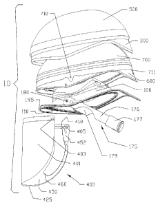
Specifically, in Figure 1 there is shown an exploded view of one embodiment
of the helmet and facial shield assembly 10 of the instant invention. The
helmet
assembly 10 includes the helmet shell 600, the liner 100, the outer filter
protector
500, the filter cover support 300, the headband assembly 175 and the facial
shield
400 which comprises the lens 401 and the cuff (or seal) 450.
The headband 175 is used to seat the helmet 10 on the head of the wearer
590. The headband 175 is fairly conventional and is, also, optional. That is,
a
different head engaging support mechanism can be utilized or it can be
omitted, if
preferred.
In this illustrative embodiment, the headband 175 includes the head-
encircling band 176 which is adjustable to comfortably fit the head size of
the
individual wearer. The adjustment latch 177 permits the band 176 to be
shortened
or lengthened in a conventional manner.
The band 176 includes suitable attachment arms 179 for attachment to the
helmet liner 100 by means of suitable fasteners 180 which can be screws,
staples,
or the like.
The helmet liner 100 is, typically, formed of a lightweight material, such as
polypropylene or LDPE, for example. Helmet liner 100 is configured to conform,
generally, to the shape of the upper portion of the wearer's head but to be
spaced
away from the top of the head of the wearer by the appropriate spaces 101 and
102
(see Figure 3) which can be formed in the helmet, foam pads or the like.
5
CA 02683259 2009-10-19
The frontal portion of the liner is designed to span the area between the
forehead
of the wearer wherein surface 120 acts as the front portion of the headband
175 or is in
juxtaposition sufficiently close to minimize airflow therebetween. A surface
130 extends
to the outer edge 140 of the liner which may attach to the lower perimeter of
the helmet
600, if so desired. The spanning effect may also be accomplished in whole or
in part by
foam inserts, if so desired.
A plurality of holes 150 (seen best in Figures 3 and 3A) extend upwardly
through
the surface 130 of the liner 100 to provide for airflow therethrough and
toward the
contained volume about the face or the wearer.
The liner 100 has an accordion-like area 110 (better seen in Figure 3A) which
permits the liner 100 to flex and better conform to the wearer's head.
In addition, if desired, the liner 100 is sufficiently sturdy to support a
cooling or air
moving mechanism such as a respirator helmet 600 or the like as known in the
prior art.
The respirator helmet may be attached to the liner by a snap in groove, 195
around the
perimeter of the liner or any other conventional means.
A fan covering (not shown) can be joined to or integrally formed to provide a
protective and contouring cover for fan mechanism of any conventional type as,
for
example, described in U.S. Patent Nos. D460,584 and 6,792,944. Thus, air flow
channels can be defined and maintained around the helmet assembly 10 whereby
an
optional fan mechanism can provide a cooling and filtered air flow to the
wearer of the
helmet assembly 10.
A filter 700, typically, but not limitatively, fabricated of electrostatically
charged
fibrous plastic material (e.g., melt blown polypropylene) is configured to
conform to the
6
CA 02683259 2009-10-19
outer shape of the helmet shell 600 and is adapted to fit fairly snugly
thereto. Features
as described in US Patent No. 6,918,141 (noted supra) support the filter and
create an
air channel beneath it. Alternately, the filter may be so designed as to be
self
supporting. The level or degree of filtration of air which enters or leaves
the helmet
shell 600 can be controlled by appropriate selection of the material of the
filter 700,
Filter 700 is, typically, mounted to the helmet shell 600 with a force
friction fit and
by snaps around the perimeter of the helmet as illustrated by side and rear
snaps 710
and 711. Of course, any suitable fastener can be utilized. As will be
described infra,
the top edge of lens 400 is attached to the perimeter of the helmet shell 600,
the liner
100, or the filter cover support 300, if so equipped.
In this embodiment, a filter protector 500 is provided to cover the filter
700. The
filter protector 500 can be fabricated of a material which is the same as (or
similar to)
helmet liner 100, if so desired. The filter protector 500 prevents damage to
the filter 700
and, as well, prevents persons (including the helmet wearer) from touching the
possibly
contaminated surface of filter 700. The filter protector 500 is attached to
the helmet
shell 100, typically, by a force-fit or any other technique.
The rear deck (or tail) 187 of the helmet liner 100 engages the rear edge of
helmet 600 and provides additional stability to the apparatus.
A facial lens 401 fabricated of an impermeable, flexible and transparent
material
such as polycarbonate, or the like, is adapted to be mounted to and bear
against the
outer front surface of filter cover support, as described infra. The
juxtaposition of the
inner surface of the lens 401 and the outer surface of the filter cover
support provides a
7
CA 02683259 2016-01-06
seal therebetween. A sealing means 410 as described infra or other suitable
means may be provided to enhance the seal.
The cuff 450 is fabricated of a sheet of pliant material such as rayon or thin
plastic or meltblown polypropylene. The cuff 450 also serves as a protective
barrier
to prevent particulate material from being transmitted to or from the wearer
to or
from the ambient.
The cuff 450 is attached to the lens 401 along a seam 425. The mid-portion
of cuff 450 is adapted to be tucked under the chin of the wearer.
Referring now to Figure 34, there is shown an enlarged view of a portion of
the view of the apparatus shown in Figure 3. This enlarged view shows the
arrangement of the holes 150, the accordion-like area 110.
Also, the interaction of the shield 400, the liner 100, and the support tabs
452
and 453 is shown in greater detail.
Notably, the upper edges 456 and 457, respectively, of support tabs 452 and
453 are held in close proximity to the extension of liner surface 130.
Likewise, the
support tabs maintain the upper extensions 461 and 462 of cuff free edge 451
in
close proximity to the wearer's head, as better seen in Figure 5.
Thus, it is contemplated that facial shield 400 comprising lens 401 and
protective cuff 450 can be joined together as a subassembly and placed over
the
hetmet shell 600, in concert with liner 100 or spanning means to define an
enclosed
volume about the face of the wearer thereby providing or enhancing the
filtering and
protecting functions described.
8
CA 02683259 2009-10-19
The M-shaped cuff 450 includes the enlarged portion 460 at the mid-portion
thereof. This "bump" or "nose" portion is provided in order to provide a
secure
engagement under and with the chin of the wearer of the helmet.
Suitable connectors (or attachments) 403, 404 and 405, such as sections of
hook-and-loop material, holes for engaging snap posts or an adhesive strip may
be
applied near the upper edge 402 of lens 401. These connectors (or adhesive
strip) can
be used to attach the upper edge 402 of lens 401 to the front of the helmet
liner 100,
helmet 600 or filter protector support 300 (see Figures 1 and 4).
In some embodiments it may be desirable to have a strip 410 of sealing
material
such as foam, a rubber tube or other compressible strip which can engage the
front of
the liner 100 or helmet 600 providing an enhanced seal thereto.
In a preferred embodiment the seal is a thin strip 410 of pretensioned elastic
applied flat to lens 401 and adhered along one side to create a fixed edge 412
and a
free edge 411 such that when the lens 401 is bent the free edge 411 will seek
a smaller
radius of curvature, with an arc length closer to its untensioned length, than
the fixed
edge 412. This causes the surface 413 to tend toward perpendicular to the
surface of
lens 401. Thus an inexpensive gasket is produced with a spanning capability
equivalent
to the width of surface 413.
Referring now to Figures 4, 5 and 6, there is shown a typical application of
the
lens/cuff assembly. (The helmet 10 is omitted from Figures 5 and 6 for clarity
of
description. Moreover, the shield 400 can be used with many types and shapes
of
helmets which incorporate a suitable connector or attachment mechanism.)
9
CA 02683259 2016-01-06
=
As seen, the cuff 450 is separated from the lens 401 (except at the joinder
edge 425). Concurrently, the lens 401 is curved into a generally semi-circular
configuration to surround the wearer's head.
The connectors 403 and 404 (a similar connection 405 is seen in Figure G)
are attached to a counterpart connector on the front of the filter cover
support 300
(not shown). Thus, the lens 401 assumes a curvilinear configuration in front
of the
face to the wearer 590 of the helmet.
At the same time, the cuff 450, in particular the nose 460 (see Figures 7 A,
7B and 7C) is placed under the chin of the wearer 590 to enhance the gripping
of
the chin by the cuff and the protection provided thereby. The edge 451 of the
cuff
450 otherwise engages the neck and throat area of the wearer 590, as best seen
in
Figure 5. The cuff 450 also engages the sides of the head of the wearer 590
and
forms a protective surface therearound.
The flexible support tabs 452 and 453 are arranged to cause the cuff 450 to
maintain the preferred shape surrounding the head of the wearer 590, as
described
supra. Specifically they interact with the tension created along the edge 451
by the
insertion of the wearers face to draw the upper extension of the free edge 462
(and
similarly 461 shown in Figure 6) into contact or close proximity of the temple
area of
the wearers head thus extending away from the joinder edge 425 into abutment
with
the upper or temporal portion of the head of the wearer 590.
The optional slots 454 and 455 are provided to accept and engage a portion
of the edge of the helmet liner 100, if desired.
CA 02683259 2009-10-19
In Figure 6, there is shown a perspective view of the lens and cuff attachment
to
be used with the helmet shell 100 shown in prior Figures 1, 2 and 3.
As described supra, the lens 401 is fabricated of a thin sheet of transparent
polycarbonate (or similar) plastic. A suitable thickness is about 0.01 inches
thick
although thicker or thinner materials may be used.
The cuff 450 is fabricated of a suitably supple material such as but not
limited to
rayon, meltblown polypropylene, latex rubber or the like and is about 0.01
inches thick
dependant on the characteristics of the material.
The lens 401 and cuff 450 are joined together at the curved edge 425 by any
suitable means such as gluing, stitching or the like.
The free edge 402 of lens 401 is shaped to properly mate with the front edge
of
the helmet liner 100 and/or filter protector support 300, as described supra.
The free edge of the cuff 451, in a preferred embodiment, is formed in an
undulating, generally, M-shape with nose 460, better seen in Figures 7A, 78
and 70.
Support tabs 452 and 453 can be provided at the upper ends of the cuff 450
adjacent to the respective ends of the curved end 425. The support tabs permit
advantageous fitting of the cuff to helmet. Typically, the tabs 452 and 453
are flexible
about an axis parallel to the flat surface of the tab but less so in other
directions.
In some embodiments, it is desirable to provide the slits 454 and 455 for
engaging the edges of the helmet liner 100.
Referring concurrently now to Figure 7, and particularly to Figures 7A, 78 and
70, there are shown additional embodiments of the shield combination 400 of
lens 401
and cuff 450. Figures 7A, 78 and 70 demonstrate the ability of these devices
to be
11
= CA 02683259 2016-01-06
manufactured in a flat or two-dimensional configuration which is more easily
achieved with automated production equipment.
In Figure 7A, the lens 401 includes an adhesive band 408 attached at the
upper edge thereof. The adheshive band 408 replaces the hook-and-loop
connectors 403, 404 and 405, holes 403A, 404A, and 405A or other features are
used to assist in alignment. The adhesive band 408 be a multiple use adhesive
for
re-adhering the shield to the helmet, if desired. Typically, the adhesive band
408 is
a tacky material so that the shield 400 can be removed from the helmet and
discarded after use.
In this embodiment, the flexible supports 452 and 453 include the slots 454
and 455 therein. In addition, flexible gores 406 and 407 are included between
the
ends of the cuff 450 and the supports 452 and 453, respectively. The flexible
gores
permit some stretchability or elasticity in the structure of cuff 450. The
gores can be
fabricated of any suitable stretchable material such as spandex or latex
rubber.
In Figure 7B, there is shown another embodiment of the shield 400. In this
embodiment, the lens 401, similar to the lens 401 in Figure 7A in that it
includes an
adhesive band 408 and/or attachment features 403, 404, and 405 at the edge
thereof. The nose 460 is provided along the free edge 451 of the cuff 450.
In the embodiment shown in Figure 7B, the cuff 450A has elongated end
portions 470 and 471 which extend beyond the edge 402 and band 408 of the lens
401. An elastic band (or cord) 480 is affixed to the ends 470 and 471 in any
suitable fashion.
12
CA 02683259 2016-01-06
The elastic band 480 can be stretched to pass over the helmet, head and/or
nape of the neck of the wearer and then contract to form a reasonably snug but
comfoftable fit of the cuff 450A to the wearer. This structure allows the
entire cuff to
be made of a less expensive non-stretchable material such as SMS polypropylene
or a cellulose non-woven. Alternatively, a tie, drawstring or other securing
means
can be used to secure the helmet/shield apparatus to the wearer. The lens 401
and
cuff 450, thus, provide a protective barrier for the face of the wearer.
In Figure 7C, there is shown another embodiment of the shield 400. In this
embodiment, the lens 401 and adhesive band 408 are similar to those shown in
Figure 7B. Likewise, the cuff 450A with the elongated ends 470 and 471 is
shown.
However, in this embodiment, the ends 470 and 471 include openings 490
and 491, respectively therethrough.
In this case, the openings (or holes) 490 and 491 can be utilized to engage
suitable mounting devices, such as knob 115 shown on the helmet liner 100 in
Figure 3.
Alternatively, a cord, elastic band, or other suitable securing components
attached to helmet liner 100 can be utilized, as well.
Referring now to Figure 8, particularly the embodiment shown in Figure 8A,
the entire cuff 450B can be made of an extremely stretchable material with an
elasticity of greater than 300%, such as latex or silicone rubber. In this
structure the
free edge of the cuff 450B can assume any shape. The support tabs 452 and 453
or similar features would provide means to draw the free edge into
communication
13
CA 02683259 2016-01-06
with the wearers head. As these materials tend to be expensive or
uncomfortable
against the wearers face this is considered less desirable.
Referring to Figure 8B, the lens and cuff assembly 400 may be attached to a
hood 800 such as is described in US Patent No. 5,054,480; Bare, et al noted
supra.
The hood 800 is designed for use with a similar helmet structure as previously
described. Within the hood 800, the cuff 450 defines a smaller space volume
about
the face of the wearer which is being easier to restrict contaminant entry
thereto.
In this configuration, the filter protector 300 as described supra is omitted
and
the hood 800 encloses the wearer's head, as well as the helmet. At least a
portion
810 of the hood can be constructed of a permeable material such as open cell
foam, felt or meltblown polypropylene so as to provide airflow therethrough
and into
filter 700 (see Figure 1).
If desired, the permeable portion 810 may be constructed of an
electrostatically charged meltblown polypropylene or other filter media
thereby
acting as a prefilter for filter 700, or in some instances as a filter in lieu
of filter 700.
Referring now to Figure 9, the lens and cuff assembly 400 may be attached
to a support structure allowing it to form the contained volume about the
wearers
face without requiring a ridged supporting structure or helmet.
In this configuration, lens 400 is similar to previous configurations in that
cuff
450C is attached to lens 401 about edge 425, the free edge 451 of cuff 450C
contains nose 460, support tabs 452 and 453 and stretchable gores 406 and 407
are included, if so desired.
14
CA 02683259 2016-01-06
An extension 941 to cuff 450C has free edge 947 extending from edge 451 to
create a closed profile which encircles the wearer's head. Headband 920 is
attached to free edge 947 at joinders by sewing or other conventional means.
This
arrangement causes the headband to rest against the wearer's forehead thereby
stabilizing the hood on the wearer's head. A second strap 925 is installed to
extend
across the top of the wearer's head, if desired.
A second ply 940 of material is attached to the upper edge 402 of lens 401.
The second ply is attached to cuff extension 942 along edge 945 by sewing or
other
conventional means to create a contained volume about the wearers face and
head,
if desired.
An opening 950 is provided in cuff extension 942 for attachment of an air
supply means.
Referring again to Figures 7A, 7B, 7C and 9, the areas 470A respectively,
adjacent to the free edge 451 of the cuff 450 may be cut in a pattern of
interlocking
lines (or strips) which will allow some give or stretch in a normally non-
stretchable
material such as SMS meltblown polypropylene, cellulose non-woven, or the like
as
described supra. The elastic recovery capability of this patterned area may be
enhanced by the adhesion of elastic fibers of hot melt adhesive or the like,
if so
desired.
Thus, there is shown and described a unique design and concept of a
respirator apparatus. While this description is directed to particular
embodiments, it
is understood that those skilled in the art may conceive modifications and/or
variations to the specific embodiments shown and described herein. Any such
CA 02683259 2016-01-06
modifications or variations which are within the purview of this description
are
intended to be included therein as well. It is understood that the description
herein
is intended to be illustrative only and is not intended to be !imitative.
Rather, the
scope of the invention described herein is limited only by the claims appended
hereto.
16