Note: Descriptions are shown in the official language in which they were submitted.
CA 02683382 2009-10-21
BEARING SUPPORT STRUCTURE FOR TURBINE
Technical field of the invention
The present invention refers to the technical field of turbines, specifically
to the
elements and configuration of gas turbines, and more specifically to
structural support
and rotation elements of turbines, and to the optimization thereof to improve
the
aerodynamics of the assembly, separating the strictly structural function from
the
aerodynamic one.
Background of the invention
For the housing of bearings in gas turbines, radial structures are used, where
said
bearings are housed inside them, and the turbine is fixed to its outer part.
These
structures are formed by an inner ring where the bearing is housed and an
outer ring
where the turbine anchoring points and the fastening points of the engine
assembly,
which includes the turbine, are. Nowadays, the inner ring and the outer ring
of these
radial structures are joined together by a set of blades or vanes, with an
aerodynamic
function to straighten and direct the incoming flow in the most appropriate
form, a
structural function to transmit the bearing loads to the anchoring points of
the turbine
arranged in the outer ring, and also to allow the passage of service fluids
such as oil or
air between the outside and the inside of the main fluid with a minimum
aerodynamic
impact, reason why some of the vanes must be hollow, so as to allow the
passage of
fluids through their interior. Therefore, the number of vanes needed between
the inner
ring and the outer ring is determined by the level of loads to be transmitted
between the
bearing and the turbine, the quantity and variety of service fluids needed,
and the
aerodynamic requirements. This configuration presents a series of
disadvantages
derived from the fact that since the number of vanes depends on so many and so
different factors, it is not possible to optimize the number, form and section
of said
vanes without sacrificing some of the factors, for example, an improvement in
the
support function will worsen the aerodynamic properties, and vice versa. That
is, if all
vanes are the same it will not be possible to optimize all functions at the
same time,
instead, one of them will always be sacrificed to the others.
CA 02683382 2009-10-21
-2-
Therefore, it was desirable a support structure which attained an efficient
turbine
operation, and simultaneously improved all functions of said structure,
avoiding the
existing inconveniences in the previous systems of the state of the art.
Description of the invention
The present invention solves the existing problems of the state of the art by
means of a
bearing support structure for a turbine, specifically for the rear bearing of
a gas turbine.
This support structure is formed by an inner ring, where the bearing is housed
and an
outer ring comprising in its outer perimeter some fastening points to the
turbine and
anchoring points to the engine assembly. In the present invention, the inner
ring and
the outer ring are radially connected by means of a series of vanes in a
circumference-
like arrangement between both rings, divided in structural vanes and
aerodynamic
vanes. The former will be in charge of support and load transmission functions
exclusively between the bearing and the anchoring points of the engine
assembly, in
the outer ring, and the function of service fluid passage, such as oil or air
between the
outside and the inside of the turbine operation fluid, that is why, they will
be hollow. The
latter, the aerodynamic ones, however, will be lighter than the structural
vanes, and
they will be in charge of aerodynamic functions exclusively, such as
straightening the
main flow of the turbine operation.
Thus, the number of structural vanes in a circumference-like arrangement
between the
inner ring and the outer ring depends exclusively on the loads to be
transmitted from
the bearing to the anchoring points of the engine assembly in the outer ring,
and on the
amount of service fluids which have to travel between the inner ring and the
outer ring,
and the number of aerodynamic vanes and their section depends exclusively on
the
aerodynamic requirements demanded from the support structure for the
straightening
of the turbine main flow.
With this separation of mechanical and aerodynamic functions by dividing vanes
into
structural and aerodynamic ones, it is attained the optimization of the
mechanics and
aerodynamics simultaneously, acting on the structural and aerodynamic vanes,
respectively.
CA 02683382 2009-10-21
-3-
According to different embodiments of the invention, the aerodynamic vanes,
which are
the ones which will enable the turbine aerodynamic optimization, can be joined
to the
inner ring, to the outer one, or both, through different joining systems, in
order to attain
a firm union, which also provides the necessary aerodynamic properties to the
structure.
One of these joining systems consists of using at least a two-wing metallic
flat bar with
an L-section, where one of the wings is joined to the aerodynamic vane and the
other
wing is joined to the corresponding ring. The aerodynamic vanes are joined to
each
one of the rings through at least one metallic flat bar. According to
different
embodiments, a flat bar can be used to join the vane to the inner ring and the
other flat
bar can be used to join the vane to the outer ring, or more than one flat bar
for the
union of the vane to each one of the rings. Preferably, two metallic flat bars
are used,
placing one of them at each side of the aerodynamic vane, creating a steadier
and
more secure union.
According to a particular embodiment of these unions through metallic flat
bars, the
aerodynamic vanes are joined through the flat bar to both rings, both the
inner and the
outer one, being firmly fixed to one of them and simply resting against the
flat bar wing
in the other. In this way, the fixing to the structure is efficiently
attained, and
furthermore the vanes will have certain mobility, favoring the effort release
and
improving aerodynamic properties.
According to an alternative embodiment, the aerodynamic vanes are fixed only
to one
of the rings, through a couple of metallic flat bars, leaving the other end of
the vane
free, which further favors its movement, for cases in which it is necessary.
Besides the metallic flat bars, there exist other systems for the union of
aerodynamic
vanes to the rings, such as grouping the aerodynamic vanes between two
structural
vanes through a membrane in one of its ends, which is fixed to one of the
rings, or
through two membranes, being each one of them fixed to one of the vane ends.
These
membranes can be joined to the rings in a rigid or detachable manner, through
flanges,
or they can be built-in with the other rings. It is also possible that,
instead of the two
membranes joining the rings, only one of them joins one of the rings, the
other one
remaining free, thus being one of the ends free to move.
CA 02683382 2012-04-27
4
The aerodynamic vanes can be contiguous or they can be partitioned, or divided
into
two parts, preferably by its central area, so that one of the parts is joined
to the inner
ring and the other part is joined to the outer ring.
In accordance with one aspect of the present invention, there is provided a
bearing support structure for turbines comprising
- an inner ring where the bearing is housed, and
- an outer ring comprising fastening points of the turbine and anchoring
points of the
engine assembly containing the turbine,
said support structure wherein
- the inner ring and the outer ring are radially connected by means of
- a plurality of structural vanes in a circumference-like arrangement between
both
rings, which
- transmit the bearing loads to the anchoring points of the engine assembly in
the
outer ring,
- and through which service fluids go through between the inner ring and the
outer
ring, and
- a plurality of aerodynamic vanes in a circumference-like arrangement between
both
rings, which straighten the main flow of the turbine,
- in that the aerodynamic vanes are lighter than the structural vanes,
- and also wherein
- the number of structural vanes depends exclusively on
- the bearing loads to be transmitted to the anchoring points of the engine
assembly
in the outer ring,
- the amount and kind of service fluids which must go through between the
inner ring
and the outer ring,
- and the number of aerodynamic vanes which are arranged and their section
depend
exclusively on the aerodynamic requirements demanded from the support
structure
for the straightening of the turbine main flow,
- and in that the structural vanes fulfill only structural functions and the
aerodynamic
vanes fulfill only aerodynamic functions.
CA 02683382 2012-04-27
4a
Description of the drawings
For a better understanding of the invention, the following is an illustrative
non-limiting
description of an embodiment of the invention making reference to a series of
drawings.
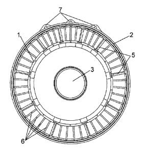
Figure 1 is a front view of the structure object of the present invention,
with the
circumference-like arrangement between the inner and outer ring of the
differentiated
structural and aerodynamic vanes.
Figure 2 is a front view of the structure object of the present invention, in
which the
aerodynamic vanes are joined only to the inner ring.
Figure 3 is a detailed view of the union of an aerodynamic vane to the inner
ring and
to the outer ring of the structure according to a particular embodiment,
through
metallic flat bars.
Figure 4 is a perspective view of the grouping of aerodynamic vanes according
to a
particular embodiment through two membranes with flanges.
Figure 5 is a perspective view of an alternative grouping of aerodynamic vanes
through two membranes without flanges.
Figure 6 is a longitudinal sectional view according to a particular embodiment
of the
union of the vanes to the rings, in which the aerodynamic vanes are joined
through
membranes in a rigid manner to the inner and outer ring.
Figure 7 is a longitudinal sectional view according to another particular
embodiment
of the union of the vanes to the rings, in which the aerodynamic vanes are
joined
through membranes in a rigid manner to the inner ring and in a detachable
manner to
the outer ring.
CA 02683382 2009-10-21
-5-
Figure 8 is a front view of a structure, in which according to a particular
embodiment
the aerodynamic vanes are divided into two parts, being one of the parts
joined to the
inner ring and the other part, to the outer ring.
In these figures, reference is made to the following set of elements:
1. outer ring
2. inner ring
3. bearing
4. turbine fastening points
5. structural vanes
6. aerodynamic vanes
7. anchoring points of the engine assembly
8. metallic flat bars
9. first wing of the metallic flat bars
10. second wing of the metallic flat bars
11. aerodynamic vanes packages
12. inner membrane
13. outer membrane
14. flanges
Description of preferred embodiments of the invention
As it can be seen in the drawings, particularly in figures 1, 2 and 8, the
object of the
present invention is a bearing support structure for turbines, specifically
gas turbines,
formed by an inner ring 1, where the bearing 3 is housed for the rotation of
the turbine,
and an outer ring 2, which in its outer perimeter has some fastening points 4
for the
turbine and some anchoring points 7 of the engine assembly. The inner 1 and
outer
ring 2 are connected by a plurality of vanes 5, 6, radially placed in a
circumferential
arrangement between them.
These vanes 5, 6 are divided into structural vanes 5 and aerodynamic vanes 6.
The
structural vanes 5 are in charge of transmitting the bearing 3 loads to the
anchoring
points 7 of the engine assembly which are in the outer ring 2, and of being
the passage
of service fluids, such as air, water or oil between the inner ring 1 and the
outer ring 2.
The aerodynamic vanes 6 are in charge of providing the aerodynamic
requirements to
CA 02683382 2009-10-21
-6-
the structure, such as for example, straightening the main flow of the turbine
operation.
Due to the difference between the function of both types of vanes 5, 6, the
aerodynamic vanes 6 are lighter than the structural vanes 5.
In the present bearing support structure for turbines, the mechanical or
structural
function and the aerodynamic one are totally separate, that is, the structural
vanes 5
only fulfill structural functions and the aerodynamic vanes 6 only fulfill
aerodynamic
functions.
Therefore, the number of structural vanes 5 placed between the inner ring 1
and the
outer ring 2 depends exclusively on the loads to be transmitted between the
bearing 3
and the anchoring points 7 of the engine assembly located in the outer ring 2,
and on
the quantity and type of service fluids which need to go through between the
inner ring
1 and the outer ring 2, while the number of aerodynamic vanes 6 and their
section
depend exclusively on the aerodynamic requirements demanded by the support
structure for the straightening of the main flow of the turbine operation.
According to different particular embodiments of the invention, the
aerodynamic vanes
6 can be joined at one of its ends to the inner ring 1, or at the other end to
the outer
ring 2, or they can be joined to both rings 1, 2. Figure 2 shows an embodiment
where
the aerodynamic vanes are only joined to the inner ring 1.
For the union of the aerodynamic vanes 6 to the rings there exist several
methods.
A preferred embodiment of these union means consists of at least a metallic
flat bar 8,
which is formed by a first wing 9 which is connected to the aerodynamic vane
6, and a
second wing 10 rigidly joined to the ring 1, 2. The aerodynamic vanes 6 are
joined to
the rings 1, 2 through at least one of these metallic flat bars 8, being it
possible to use
one metallic flat bar 8 for the union of the aerodynamic vane 6 to each one of
the ring,
or more than one metallic bar. Figure 3 shows that preferably a couple of
these metallic
flat bars 8 are used, placing one at each side of the aerodynamic vanes 6.
Figure 3
shows that preferably each one of the aerodynamic vanes 6 is joined at one of
its ends
to the inner ring 1 through a couple of metallic flat bars 8, and at its other
end to the
outer ring 2 through another couple of metallic flat bars 8. In this case, the
first wings 9
of the flat bars 8 joining the aerodynamic vanes 6 to the inner ring 1 are
rigidly fixed to
CA 02683382 2009-10-21
-7-
the aerodynamic vanes 6, while the first wings 9 of the flat bars 8 joining
the
aerodynamic vanes 6 to the outer ring 2 only rest against said aerodynamic
vanes 6,
offering certain degree of mobility which will favor tension release and a
better position
of the vane 6 as regards aerodynamic properties. According to an alternative
embodiment, the first wings 9 of the flat bars 8 joining the aerodynamic vanes
6 to the
outer ring 2 are the ones rigidly fixed to the aerodynamic vanes 6, while the
first wings
9 of the flat bars 8 joining the aerodynamic vanes 6 to the inner ring 1 are
the ones that
only rest against said aerodynamic vanes 6. This embodiment is similar to the
previous
one, except in that the mobility is produced in the proximity of the inner
ring 1 and not
of the outer ring 2.
According to another embodiment of the invention, the aerodynamic vanes 6 are
joined
only to one of the rings 1, 2 through two metallic flat bars 8 arranged one at
each side
of the aerodynamic vane 6.
Alternatively to the metallic flat bars 8, the present invention has other
means for
joining the aerodynamic vanes 6 to the rings 1, 2. Figures 4 and 5 show the
package
grouping 11, of different aerodynamic vanes 6, preferably all those that are
arranged
between structural vanes by means of an inner membrane 12 which is fixed to
one of
their ends, and to the inner ring 1, and an outer membrane 13, which is fixed
at the
other end thereof and to the outer ring 2. As shown in figures 4 and 6,
according to a
particular embodiment of the invention, the inner 12 and outer membranes 13
are
rigidly fixed to the inner 1 and outer 2 rings, respectively through flanges
14 arranged
at the edge of the membranes 12, 13. Alternatively, the packages 11 of
aerodynamic
vanes 6 are rigidly fixed to one of the two rings 1, 2 while they are joined
to the other in
a detachable way, through the introduction of a flange 14 in a groove to that
purpose,
and which enables the packages 11 of aerodynamic vanes 6 to move in a radial
direction, favoring the aerodynamic properties of the support structure.
Figure 7 shows
this embodiment, in which the packages 11 are rigidly fixed to the inner ring
1 and
joined to the outer ring 2 in a detachable way. Furthermore, according to a
different
embodiment, one of the membranes 12, 13 is fixed to one of the rings 1, 2
while the
other membrane 13, 12 is free from the other ring 2, 1, thus offering mobility
to that end
of the aerodynamic vanes.
CA 02683382 2009-10-21
-8-
According to different embodiments, the flanges 14 are eliminated to the
membranes
12, 13, being said membranes 12, 13 integral to the rings 1, 2 when the
packages 11
are fixed to them, or remain free.
Figure 8 shows a particular embodiment of the invention in which the
aerodynamic
vanes 6 are divided into two parts, preferably at its central area, so that
one of the parts
is joined by any of the means described to the inner ring 1, and the other
part is joined
by any of the means described to the outer ring 2.
Once the invention has been clearly described, it is worth stating that the
previously
described embodiments can be subject to detail modifications as long as the
main
principle and essence of the invention are not modified.