Note: Descriptions are shown in the official language in which they were submitted.
CA 02683686 2009-10-07
WO 2008/122961 PCT/IB2008/051347
1
EASY-OPENING FLEXIBLE CONTAINER
FIELD OF THE INVENTION
This invention relates to a flexible container enclosing articles to be
dispensed through an
aperture.
BACKGROUND OF THE INVENTION
Many types of household and personal care articles, such as dust cloths,
wipes, wet wipes,
facial cloths, and baby cloths may be packaged inside flexible containers. In
a typical flexible
container for packaging such goods, a flexible pouch is formed of a flexible
sheet material.
Access into the interior of the pouch is typically provided by way of a
dispensing aperture in the
sheet material.
The dispensing aperture is typically closed by a flexible sealing member to
prevent
contamination and/or drying of the article(s) contained inside the pouch prior
to use. The
flexible sealing member is typically adhered to the pouch by means of an
adhesive. At one end
of the flexible sealing member, a lifting tab is typically provided for use in
lifting the flexible
sealing member in order to expose the dispensing aperture and thereby gain
access to the interior
of the pouch.
Some flexible containers are outfitted with rigid closure elements. A typical
rigid closure
element includes two elements that interlock, such as a base that is adhered
to the pouch and a
hinged lid. However, such a rigid closure element may fail to seal tightly and
thereby fail to
prevent contamination of the article(s) and/or moisture loss from article(s)
such as wet wipes.
One solution has been to provide both a flexible sealing member to close the
dispensing aperture
and a rigid closure element to cover both the flexible sealing member and the
dispensing
aperture.
When only a flexible sealing member or only a rigid closure element is
present, the
requirement for its placement during manufacture is simply that the flexible
sealing member or
the rigid closure element must close the dispensing aperture, thereby
preventing exposure of the
enclosed article(s). In order to facilitate meeting this requirement, the
flexible sealing member
or the rigid closure element may be made substantially larger than the
dispensing aperture, such
that minor misplacement does not result in a failure to close the dispensing
aperture.
CA 02683686 2009-10-07
WO 2008/122961 PCT/IB2008/051347
2
However, when both a flexible sealing member and a rigid closure element are
present,
their placements are interrelated. For example, relative misplacement of the
rigid closure
element may obstruct the lifting tab on the flexible sealing member and
thereby prevent the user
from lifting the flexible sealing member for access to the enclosed
article(s). Since the rigid
closure element is typically strongly secured to the flexible pouch, the user
is then forced to
open the flexible container in some other way, such as cutting or tearing the
flexible pouch. Of
course, a flexible pouch that has been cut or torn open typically cannot be
resealed, and the
original purpose of enclosing the article(s) inside the flexible container is
thus defeated.
The relative misplacement of either the flexible sealing member or the rigid
closure
element may also result in higher manufacturing cost due to the scrapping of
defective product
and/or the necessity to spend more on equipment, training, and inspection in
order to minimize
the number of defective products reaching the users. In addition, users who
encounter defective
products may lose faith in the product.
Hence, it would be beneficial to provide a flexible container having both a
flexible sealing
member and a rigid closure element configured such that the problems described
above would
be less likely to occur.
SUMMARY OF THE INVENTION
A flexible container includes a flexible pouch having a dispensing aperture
through which
an interior space is accessible from outside the flexible pouch, a flexible
sealing member
releasably attached to the flexible pouch and covering the dispensing
aperture, and a rigid
closure element surrounding the dispensing aperture. The flexible sealing
member has at least
two lifting tabs for lifting the flexible sealing member and thereby exposing
the dispensing
aperture. The rigid closure element has a base attached to the flexible pouch
and lid connected
to the base by a hinge. At least one of the lifting tabs is likely to not be
obstructed by the rigid
closure element when the lid is in an open condition, thereby remaining usable
for lifting the
flexible sealing member to expose the dispensing aperture, even if another
lifting tab is
obstructed by the rigid closure element.
BRIEF DESCRIPTION OF THE DRAWING
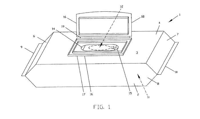
Figure 1 shows a perspective view of an exemplary flexible container.
Figure 2 shows a perspective view of another exemplary flexible container.
CA 02683686 2009-10-07
WO 2008/122961 PCT/IB2008/051347
3
DETAILED DESCRIPTION OF THE INVENTION
The term "disposed" refers to an element being attached and positioned in a
particular place
or position in a unitary structure with other elements.
The term "attach" refers to elements being connected or united by fastening,
adhering,
bonding, etc. by any method suitable for the elements being attached together
and their
constituent materials. Many suitable methods for attaching elements together
are well-known,
including adhesive bonding, pressure bonding, thermal bonding, etc. Such
attachment methods
may be used to attach elements together over a particular area either
continuously or
interniittently. Unless indicated otherwise, elements that are described as
being attached to each
other are attached directly together, with either nothing or only bonding
material, e.g., an
adhesive, between them. Elements may be attached "permanently", i. e. ,
attached in such a way
that one or both of the elements and/or any bonding material that is present
must be damaged in
order to separate them. This permanent attachment excludes temporary
attachment, such as
fastening elements together by means of fasteners that may be unfastened.
Alternatively,
elements may be attached "releasably", i.e., attached in such a way that
neither of the elements
needs to be damaged in order to separate them.
The term "laminate" refers to elements being attached together in a layered
arrangement.
The term "cohesive" refers to the property of a material that, once set,
sticks to itself but
does not to any significant degree stick to other materials.
The terms "water-permeable" and "water-impermeable" refer to the penetrability
of
materials in the context of the intended usage of disposable absorbent
articles. Specifically, the
term "water-permeable" refers to a layer or a layered structure having pores,
openings, and/or
interconnected void spaces that permit liquid water to pass through its
thickness in the absence
of a forcing pressure. Conversely, the term "water-impermeable" refers to a
layer or a layered
structure through the thickness of which liquid water cannot pass in the
absence of a forcing
pressure. As is well known in the art, a common method for measuring the
permeability to
water of the materials is a hydrostatic pressure test, also called a
hydrostatic head test or simply
a "hydrohead" test. Suitable well known compendial methods for hydrohead
testing are
approved by INDA (formerly the International Nonwovens and Disposables
Association, now
The Association of the Nonwoven Fabrics Industry) and EDANA (European
Disposables And
Nonwovens Association).
CA 02683686 2009-10-07
WO 2008/122961 PCT/IB2008/051347
4
The term "nonwoven" refers to a sheet, web, or batt of directionally or
randomly oriented
fibers, made by bonding or entangling the fibers through mechanical, thermal,
or chemical
means. Nonwoven materials exclude paper and products which are woven, knitted,
tufted, or
felted by wet milling. The fibers are preferably but not necessarily man-made
synthetics.
A flexible container may have any shape suitable for enclosing its contents,
such as a stack
or a roll of substrate sheets, such as wipes. For example, the flexible
container may be
cylindrical, polygonal, or parallelepipedal in shape.
Each of Figure 1 and Figure 2 illustrates an exemplary embodiment of a
flexible container
1 in which a flexible pouch 2 is formed of a flexible polymeric sheet material
3, which may be
water-impermeable if the need to contain moisture or the need to exclude
moisture exists, or
may be water-permeable if neither of these needs exists. The flexible pouch 2
has a top wa114,
an opposing bottom wall (not shown in the figures for clarity), opposing end
walls 6 and 7, a
front side wall 8, and an opposing rear side wall (not shown in the figures
for clarity), arranged
in a generally parallelepipedal configuration. The opposing end walls 6 and 7
are closed by end
seals 9 and 10. The walls define and enclose the interior space 11 of the
flexible pouch 2.
The flexible pouch 2 has a dispensing aperture 12 in its top wall 4. Such a
dispensing
aperture may be made in another of the walls, instead of or in addition to the
top wall. The
dispensing aperture 12 may be fully formed in the manufacturing process or may
be defined, but
not cut out, by perforation of the sheet material 3. The exemplary dispensing
aperture 12 shown
in the figures has a relatively simple oval shape. The dispensing aperture 12
may have a
different relatively simple shape, such as a rectangular shape, or may have a
relatively complex
shape, such as a generally rectangular shape with rounded corners, or a shape
with multiple
protrusions. In general, the dispensing aperture 12 may have any shape
suitable for access into
the interior space 11 of the flexible pouch 2.
A flexible sealing member 13 overlies the dispensing aperture 12 and extends
beyond the
dispensing aperture in all directions so as to also overlie the immediately
surrounding area and
thereby cover the entirety of the dispensing aperture 12. The flexible sealing
member 13 is
formed of a flexible material, which may be identical to the sheet material 3
of which the
flexible pouch 2 is formed. The flexible sealing member 13 is releasably
attached to the flexible
pouch 2 by any method suitable for the materials involved, including, for
example, adhesive
attachment, cohesive attachment, or a combination of suitable methods. In
embodiments in
which the dispensing aperture 12 is only defined, but not cut out, by
perforation in the
CA 02683686 2009-10-07
WO 2008/122961 PCT/IB2008/051347
manufacturing process, the formation of the dispensing aperture 12 may be
completed by the
user when lifting the flexible sealing member 13, at which time the attachment
of the flexible
sealing member 13 to the sheet material 3 may cause the weakened sheet
material 3 to tear
where it was perforated.
The flexible sealing member 13 has lifting tabs 14 and 151ocated along the
periphery of the
flexible sealing member 13. These lifting tabs 14 and 15 adapted to be grasped
by a user and
used to lift the flexible sealing member 13 away from the surface of the
flexible pouch 2 to
thereby expose the dispensing aperture 12. In the embodiment of Figure 1,
opposing lifting tabs
14 and 15 are located along the periphery of the flexible sealing member 13
near the opposing
end walls 6 and 7 of the flexible pouch 2. Such lifting tabs may be provided
along the periphery
of the flexible sealing member 13 near the side walls of the flexible pouch 2,
instead of or in
addition to the locations shown in Figure 1. Similarly, such lifting tabs may
be provided
anywhere along the periphery of the flexible sealing member 13, instead of or
in addition to the
locations shown in Figure 1 or previously described. For example, in the
embodiment of
Figure 2, the lifting tabs 14 and 15 are located along the periphery of the
flexible sealing
member 13 in adjacent quadrants of the flexible sealing member 13, i.e., one
lifting tab 14 is
located relatively nearer the end wall 6 of the flexible pouch 2 and the other
lifting tab 15 is
located relatively nearer the front side wa118 of the flexible pouch 2.
The exemplary flexible sealing member 13 shown in the figures has a relatively
simple oval
shape and each of the lifting tabs 14 and 15 is shown in the figures as having
the relatively
simple shape of a segment of the oval. The flexible sealing member 13 may have
a different
relatively simple shape, such as a rectangular shape, or may have a relatively
complex shape,
such as a generally rectangular shape with rounded corners, or a shape with
multiple protrusions.
In general, the flexible sealing member 13 may have any shape suitable for
covering the aperture
12. Likewise, each of the lifting tabs 14 and 15 may have a different
relatively simple shape,
such as a rounded shape or a rectangular shape, or may have a relatively
complex shape, such as
a shape with multiple protrusions. In general, each of the lifting tabs 14 and
15 may have any
shape suitable for being grasped by the user. The exemplary lifting tabs 14
and 15 shown in the
figures generally conform to the general contour of the flexible sealing
member 13. In some
embodiments, the lifting tabs 14 and 15 may have the forms of distinct
protuberances projecting
outward from the general contour of the flexible sealing member 13.
CA 02683686 2009-10-07
WO 2008/122961 PCT/IB2008/051347
6
The provision of multiple lifting tabs reduces the likelihood that the user
will not be able to
lift the flexible sealing member to gain access to the article(s) enclosed
inside the interior space
of the flexible pouch. In particular, if relative misplacement of the flexible
sealing member and
the rigid closure element results in the obstruction of one of the lifting
tabs, another lifting tab
will likely remain usable. Likewise, if one lifting tab is defective in some
way, such as by being
adhered securely to the flexible pouch, it is likely that another lifting tab
will remain usable.
Additionally, the provision of multiple lifting tabs makes it possible to open
the dispensing
aperture with either hand, thus facilitating access to the enclosed article(s)
by both left-handed
and right-handed users, as well as by a user whose one hand is occupied in a
task, such as
holding a child, and who therefore must use his or her free hand, which may be
left or right, to
reach for the enclosed article(s).
The lifting tabs may be free of attachment to the flexible pouch or may be
attached
relatively weakly in comparison to the remainder of the flexible sealing
member, such as by an
adhesive having a low peel force or simply by a lighter coverage of adhesive
than is used to
attach the remainder of the flexible sealing member to the flexible pouch.
Another way of
attaching the lifting tabs relatively weakly to the flexible pouch is to
provide an adhesive on one
surface and a silicone coating on the mating surface. Relatively weakly
attached lifting tabs may
be desirable because they may remain adhered to the flexible pouch wall during
its
manufacturing process and thereby decrease the possibility of entanglement in
the
manufacturing equipment.
A rigid closure element 16 is attached onto the top wall 4 of the flexible
pouch 2. This
rigid closure element 16 has a base 17 and a lid 18. As is known in the art,
such a base and a lid
may be connected by a relatively flexible flap forming a hinge 19 as shown in
the figures, or
may be connected by a multi-piece hinge mechanism. In the figures, the lid 18
is shown in an
"open" condition in which the flexible sealing member 13 and the dispensing
aperture 12 are
accessible. The base 17 and the lid 18 may engage in any suitable manner such
that the lid will
remain in a "closed" configuration once engaged with the base 17. In order to
subsequently gain
access to the flexible sealing member 13 and the dispensing aperture 12, the
base 17 and the lid
18 must be disengaged such that the lid 18 can be swung on the hinge 19 to the
"open" condition
shown in the figures.
The exemplary rigid closure element 16 shown in the figures has a relatively
simple
rectangular shape. The rigid closure element 16 may have a different
relatively simple shape,
CA 02683686 2009-10-07
WO 2008/122961 PCT/IB2008/051347
7
such as a round shape or an oval shape, or may have a relatively complex
shape, such as a
generally rectangular shape with rounded corners, or a shape with multiple
protrusions. In
general, the rigid closure element 16 may have any shape suitable for covering
the aperture 12.
Examples of suitable engaging bases and lids can be found in U.S. Patent No.
4,156,493,
U.S. Patent No. 4,185,754, U.S. Patent No. 6,702,109, U.S. Patent Application
Publication No.
2005/0150785, U.S. Patent Application Publication No. 2005/0189367, U.S.
Patent Application
Publication No. 2005/0011906, U.S. Patent Application Publication No.
2007/0023436, and
PCT Publication No. WO 00/064755.
The base 17 is attached to the sheet material 3 of the flexible sealing member
13 by any
method suitable for the materials involved. This attachment may be permanent
or releasable.
As shown in Figure 1, the base 17 is disposed so as to surround the dispensing
aperture 12 at a
distance from it. The rigid closure element 16 is preferably placed so as to
likewise surround the
flexible sealing member 13 at a distance from it, thereby leaving both of the
lifting tabs 14 and
15 accessible and usable. However, as explained above, some degree of relative
misplacement
of the rigid closure element 16 and the flexible sealing member 13 may be
acceptable because of
the provision of the multiple lifting tabs 14 and 15, which increases the
likelihood that at least
one of the lifting tabs will remain usable, even if the relative misplacement
is so great that
another lifting tab is obstructed.
Each of the flexible pouch, the flexible sealing member, and the rigid closure
element may
be formed partially or wholly of a polymeric material, as is typical in the
art. The polymeric
material(s) utilized in the flexible pouch and/or the flexible sealing member
may have the form
of a film and may include only a single layer or multiple layers in a laminate
structure. Such a
laminate structure may include more than one film and/or may include a layer
or layers in other
forms, such as a fibrous sheet or a foil.
The rigid closure element may be formed partially or wholly of a moldable
thermoplastic
material, such as polypropylene, polyethylene, polystyrene, acrylonitryl
butadiene styrene
(ABS), polyester, polyvinyl chloride, polycarbonate or elastomer, or a blend
of these materials.
The rigid closure element may also, or alternatively, be formed partially or
wholly of other
materials, such as cardboard, corrugated paper, wood, cardstock, paper,
ceramic, and
combinations thereof.
The disclosures of all patents, patent applications and any patents which
issue thereon, as
well as any corresponding published foreign patent applications, and all
publications listed
CA 02683686 2009-10-07
WO 2008/122961 PCT/IB2008/051347
8
and/or referenced in this description, are hereby incorporated herein by
reference. It is expressly
not admitted that any of the documents or any combination of the documents
incorporated
herein by reference teaches or discloses the present invention. To the extent
that any meaning or
definition of a term in this document conflicts with any meaning or definition
of the same term
in a document incorporated by reference, the meaning or definition assigned to
that term in this
document shall govern.
While particular embodiments of the present invention have been illustrated
and described,
it would be obvious to those skilled in the art that various other changes and
modifications can
be made without departing from the spirit and scope of the invention. It is
therefore intended to
cover in the appended claims all such changes and modifications that are
within the scope of this
invention.