Note: Descriptions are shown in the official language in which they were submitted.
i _t CA 02683987 2009-10-15
WO 2008/125270 1
PCT/EP2008/002827
An antenna of an electromagnetic probe for investigating geological formations
FIELD OF THE INVENTION
The invention relates to an antenna of an electromagnetic probe for measuring
the
electromagnetic properties of a subsurface formation in a limited zone
surrounding a
borehole. Another aspect of the invention relates to a logging tool for
performing logs of
subsurface formation borehole. Another aspect of the invention relates to a
method of
investigation of the limited zone surrounding the borehole. A particular
application of the
probe and the logging tool according to the invention relates to the oilfield
services
industry.
BACKGROUND OF THE INVENTION
Logging devices that measure formation electromagnetic properties (e.g.
dielectric
constant) are known, for example from US 3,849,721, US 3,944,910 and US
5,434,507.
Typically, a logging device includes a transmitter and spaced receivers
mounted in a
pad that is urged against a borehole wall of a well bore filled with drilling
mud.
Microwave electromagnetic energy is transmitted into the formations, and
energy that
has propagated through the formations is received at the receiving antennas.
The
phase and amplitude of the energy propagating in the formation is determined
from the
receiver output signals. The dielectric constant and the conductivity of the
formations
can then be obtained from the phase and amplitude measurements.
The transmitters and receivers comprise antennas that are assimilated to
magnetic
dipoles. These dipoles are tangential to the pad face and are orientated in
different
directions. A broadside mode corresponds to the dipoles oriented orthogonally
to the
pad-axis. An endfire mode corresponds to the dipoles oriented in alignment
with the pad
axis. The depth of investigation for the broadside mode is very poor. The
investigation
depth for the endfire mode is greater than for the broadside mode, but the
signal is
usually weaker, for example at 1 GHz. The attenuation and phase-shift are
measured
between the two receivers. A simple inversion allows in case of a homogeneous
formation to retrieve the dielectric constant and the conductivity. Typically,
such a
logging device is unable to provide an accurate measurement of the formation
properties because of its high sensitivity to the standoff of the pad
relatively to the
formation or the presence of a mudcake on the borehole wall. For example, in
the
presence of a mudcake layer the number of unknowns increase from two unknown,
namely the permittivity E and the conductivity a of the formation to five
unknowns,
CA 02683987 2009-10-15
WO 2008/125270 2
PCT/EP2008/002827
namely the permittivity c and the conductivity a of the formation (c, a)gf and
of the
mudcake (c, a)mc, and the mudcake thickness tmc. Consequently, accurate
determination of the formation electromagnetic properties based on the
attenuation and
phase-shift measurements is not possible.
The patent US 5,345,179 proposes a solution to improve the logging device
response
and accuracy in the presence of a mudcake. The logging device comprises a
plurality of
cross-dipole antennas, each being located in a cavity. The cross-dipole
antenna houses
both endfire and broadside polarizations in the same cavity.
Typically, such a cross dipole antenna comprises two wires embedded in a non-
resonant cavity filled with a dielectric material and short-circuited to the
conductive
cavity wall at one end.
The current distribution J is approximated from the analogy with a short-
circuited
transmission line. The current distribution on the radiating wire in the
cavity can be
approximated to:
J(y) = Jo cos(ko [y ¨ ap
where:
- Jo is the current amplitude,
- a is the aperture size,
-1(0 is the wave number in the cavity and is equal to: ko =
- Ecavity is the relative dielectric constant of the material filling the
cavity,
- w is the angular frequency, and
- c is the speed of light in vacuum.
The current is maximal at the short-circuit location. This cosinusoidal and
asymmetric
current distribution excites a strong, parasitic electric dipole.
The current flowing on the wire, excites modes in the cavity. The dominant
mode is the
transverse electric mode TE10. This mode contributes to a radiation pattern,
which is
close to a magnetic point dipole m orthogonal to the wire. The current
distribution on the
wire will also excite parasitic modes, the dominant one being the transverse
magnetic
mode TMii. This mode corresponds to an electric dipole p normal to the
aperture.
These parasitic modes cause a strong asymmetry of the electromagnetic field Ey
and
Ez in the yz plane.
The antennas of the prior art are far from being pure magnetic dipoles. In
particular, the
parasitic electric dipole, normal to the aperture affects the measurement
accuracy.
CA 02683987 2015-06-02
3
Further, as the mudcake electromagnetic properties are not determined, the
inversion
calculation for determining the geological formation electromagnetic
properties may not be
robust.
The patent application EP 07290149.9 filed on 6 February 2007 describes an
improved
antenna associated with electronic circuitry enabling to choose the mode of
operation of the
antenna: either as a pure electric dipole or as a pure magnetic dipole.
However, the
electronic circuitry requires the use of transformers and switches, or phase-
shifters, which
are costly and lead to a certain complexity.
SUMMARY OF THE INVENTION
One goal of the invention is to propose an antenna and an electromagnetic
probe
comprising at least one of such an antenna enabling measurement of the
electromagnetic
properties of a subsurface formation in a limited zone surrounding a borehole
avoiding, at
least reducing the drawbacks of the prior art antennas and probes.
According to a first aspect, the invention relates to an antenna combining an
antenna
element having a simple mechanical design with an appropriate electronic
circuit
determining the behavior of the antenna as a superposition of a substantially
pure electric
dipole and a substantially pure magnetic dipole.
More precisely, the first aspect of the present invention relates to an
antenna of an
electromagnetic probe used in investigation of geological formations
surrounding a borehole
comprising a conductive base and an antenna element, the conductive base
comprising an
opened non-resonant cavity, the antenna element being embedded in the cavity
and
extending through the cavity, the antenna element being isolated from the
conductive base,
the antenna element being coupled to at least one electronic module via a
first and a
second port, respectively, the electronic module configured to operate the
antenna by
exciting or receiving a signal at each of the first and second ports to define
a simultaneously
superposed pure magnetic dipole and pure electric dipole, wherein a
measurement at the
pure magnetic dipole provides a deeper radial depth of investigation into the
geological
formation than a measurement at the pure electric dipole.
CA 02683987 2015-06-02
4
Advantageously, the antenna element may be a wire strip.
The cavity may have a parallelepipedic, or an elliptical, or a cylindrical
shape. The cavity
may be filled with a dielectric material.
The electronic module comprises a transmitting module comprising a first power
amplifier
coupled to the first port and a second power amplifier coupled to the second
port of the
antenna element.
Further, the electronic module comprises a receiving module comprising a first
low-noise
amplifier coupled to the first port and a second low-noise amplifier coupled
to the
second port of the antenna element.
Still another aspect of the invention relates to antenna module comprising an
antenna of an
electromagnetic probe according to the invention. The conductive base may
further
comprise a printed circuit board coupled to the antenna by means of the ports,
the printed
circuit board comprising the at least one electronic module and a control and
processing
module.
Another aspect of the invention relates to an electromagnetic logging
apparatus used in
investigation of geological formations surrounding a borehole, comprising:
- a logging tool moveable through the borehole,
- an electromagnetic probe comprising a pad mounted on the logging device,
adapted for
engagement with the borehole wall by a wall-engaging face of the pad,
- at least one antenna mounted in the wall-engaging face and used as a
transmitting
antenna,
- a plurality of spaced antennas mounted in the wall-engaging face and used
as receiving
antennas positioned in spaced relation to the transmitting antenna,
- a transmitter module adapted for energizing the transmitting antenna to
transmit
electromagnetic energy into the formations at a determined frequency according
to an
electric dipole mode and according to a magnetic dipole mode, and
- a receiver module adapted for receiving and processing an output signal
at each of the
receiving antennas representative of electromagnetic energy received from the
formations.
CA 02683987 2016-06-08
A further aspect of the present invention relates to a method of investigation
of geological
formations surrounding a borehole using an electromagnetic logging apparatus
comprising
at least one transmitting antenna and at least one receiving antenna according
to the
invention, wherein the method comprises the steps of:
5 a) running the logging apparatus through the borehole and engaging a pad
with a borehole
wall so as to define a selected zone made of a medium to be investigated,
b) performing a first set of measurements by:
b1) operating the antennas so that each antenna defines a superposed pure
magnetic dipole and pure electric dipole by activating a first port of the
transmitting
antenna, and radiating electromagnetic signals in the medium,
b2) measuring a first and a second sub-set of attenuation and phase shift of
the
electromagnetic signals having traveled in the medium between the transmitting
and
receiving antennas at a first port and a second port of the receiving antenna,
respectively,
c) performing a second set of measurements by:
c1) operating the antennas so that each antenna defines a superposed pure
magnetic dipole and pure electric dipole by activating a second port of the
transmitting antenna, and radiating electromagnetic signals in the medium,
c2) measuring a third and a fourth sub-set of attenuation and phase shift of
the
electromagnetic signals having traveled in the medium between the transmitting
and
receiving antennas at the first port and the second port of the receiving
antenna,
respectively,
d) combining the first and the second set of measurements and mathematically
extracting a
first contribution due to the pure magnetic dipole and a second contribution
due to the pure electric dipole, and
e) performing an inversion calculation based on the first and second
contribution and
determining the permittivity c and the conductivity a of the medium in the
selected zone.
The first set of measurements and the second set of measurements may be
performed
sequentially, the first and second ports being activated by electrical signals
having identical
frequencies.
CA 02683987 2015-06-02
5a
Alternatively, the first set of measurements and the second set of
measurements may be
performed simultaneously, the first and second ports being activated by
electrical signals
having different frequencies.
In a configuration where the electromagnetic logging apparatus comprises at
least two
transmitting antennas and at least two receiving antennas, the method further
comprises
performing differential measurements between the attenuation and phase shift
measured at
the ports of the at least two receiving antennas and applying a borehole
compensation
scheme so as to eliminate each antenna gain.
CA 02683987 2009-10-15
WO 2008/125270 6
PCT/EP2008/002827
The antenna for an electromagnetic probe of the invention used in geological
surveys
enables a better measurement accuracy of the formations electromagnetic
properties
than the antenna of the electromagnetic propagation tool as described in the
prior art. In
particular, with the invention, it is possible to perform accurate measurement
even if a
mudcake covers the well bore wall, and whatever the nature of the mudcake
(e.g. oil-
based-mud or water-based-mud).
Further, while in the prior art, the mode of operation of the antenna, namely
either an
electric dipole mode (EDM) or a magnetic dipole mode (MDM) is selected by the
electronic circuitry, the invention enables exciting said two modes
simultaneously and
subsequently separating them mathematically. Therefore, the electronic
circuitry
required by the invention is simpler than in the prior art.
BRIEF DESCRIPTION OF THE DRAWINGS
The present invention is illustrated by way of examples and not limited to the
accompanying figures, in which like references indicate similar elements:
FIG. 1 schematically illustrates a typical onshore hydrocarbon well location;
FIG. 2 schematically shows a cross-section view of a pad positioned into a
borehole
and contacting a mudcake formed onto the borehole wall;
FIG. 3 schematically shows a borehole wall contacting side view of a pad for
measuring
the electromagnetic properties of a subsurface formation comprising antennas
according to the invention;
FIGS. 4 and 5 are a cross-section view, and a partial perspective and cross-
section
view showing an antenna according to a first embodiment of the invention,
respectively;
FIGS. 6 and 7 are cross-section views schematically showing antennas according
to a
second and a third embodiment of the invention, respectively;
FIGS. 8 and 9 are top view schematically showing a transmitting antenna and a
receiving antenna according to the invention operated into a mixed pure
magnetic and
electric dipole mode, respectively;
FIGS. 10 and 11 illustrate portions of a transmitting circuit and a receiving
circuit
coupled to an antenna according to the invention enabling operation into a
mixed pure
magnetic and electric dipole mode, respectively;
FIG. 12 schematically shows the electronic module shown in FIGS. 3, 4, 6 and
7;
CA 02683987 2009-10-15
WO 2008/125270 7
PCT/EP2008/002827
FIG. 13 is a top and bottom graphic showing curves representing the amplitude
and the
phase of the different signals measured at the port of a receiving antenna
according to
the invention, respectively;
FIGS. 14 and 15 are graphics showing curves representing the attenuation and
the
phase-shift measured with an antenna according to the invention compared to
theoretical values, respectively; and
FIG. 16 is a diagram illustrating the steps of the method of investigation of
the invention.
DETAILED DESCRIPTION OF THE INVENTION
FIG. 1 schematically shows a typical onshore hydrocarbon well location and
surface
equipments SE above a hydrocarbon geological formation GF after drilling
operations
have been carried out. At this stage, i.e. before a casing string is run and
before
cementing operations are carried out, the wellbore is a borehole WB filled
with a fluid
mixture DM. The fluid mixture DM is typically a mixture of drilling fluid and
drilling mud.
In this example, the surface equipments SE comprise an oil rig and a surface
unit SU
for deploying a logging tool TL in the well-bore. The surface unit may be a
vehicle
coupled to the logging tool by a line LN. Further, the surface unit comprises
an
appropriate device DD for determining the depth position of the logging tool
relatively to
the surface level. The logging tool TL comprises various sensors and provides
various
measurement data related to the hydrocarbon geological formation GF and/or the
fluid
mixture DM. These measurement data are collected by the logging tool TL and
transmitted to the surface unit SU. The surface unit SU comprises appropriate
electronic
and software arrangements PA for processing, analyzing and storing the
measurement
data provided by the logging tool TL. Alternatively, the measurement data may
be
processed, analyzed and stored downhole in the logging tool TL.
The logging tool TL comprises a probe 1 for measuring the electromagnetic
properties
of a subsurface formation according to the invention. Once the logging tool is
positioned
at a desired depth, the probe 1 can be deployed from the logging tool TL
against the
borehole wall WBW by an appropriate deploying arrangement, for example an arm.
FIGS. 2 and 3 schematically show a cross-section view and a well-bore wall
contacting
face view of the probe 1. The probe 1 comprises a pad 2. The pad is a
conductive metal
housing, for example made in a metallic material like stainless steel arranged
to be
positioned in contact with a well-bore wall WBW. The pad 2 is coupled to the
tool TL by
an arm (FIG. 2 only shows a portion of said arm). The arm enables the
deployment of
CA 02683987 2009-10-15
WO 2008/125270 8
PCT/EP2008/002827
the pad 2 into the borehole WB against the well-bore wall WBW. Typically, the
borehole
is filled with drilling mud DM.
The probe 1 further comprises transmitting and receiving antennas, for example
two
transmitting antennas Tu and Td (11 stands for up and d stands for down), and
two
receiving antennas Ru and Rd. The transmitting antennas Tu and Td and the
receiving
antennas Ru and Rd are positioned in the pad along a line AA' in the pad face
arranged
to be positioned in contact with the well-bore wall WBW. The number of the
transmitting
and receiving antennas, and their positions relatively to each other, as
illustrated in FIG.
3, is only an example. The number and positions of the transmitting and
receiving
antennas may be different. Also, in the present description, each antenna is
either
always used as a transmitting antenna or always used as a receiving antenna.
Nevertheless, an antenna is not limited to a specific function; each antenna
may be
used as receiving antenna and subsequently as transmitting antenna, or vice-
versa by
means of a switch for connecting the antenna to the appropriate electronic
module
(transmitter module or receiver module).
The probe 1 further comprises an electronic arrangement 4 connected to the
transmitting and receiving antennas. Typically, the electronic arrangement 4
is designed
such that the antenna may operate in a frequency range from around 10 MHz to
around
2GHz. The electronic arrangement 4 comprises at least one transmitter module
and at
least one receiver module. Each transmitter module is arranged to excite the
transmitting antennas Tu and/or Td by applying an excitation signal. Microwave
electromagnetic energy (illustrated by dotted lines in FIG.2) is transmitted
into the
formations, and energy that has propagated through the formations is received
at the
receiving antennas. Each receiver module is arranged to determine an
attenuation and
a phase shift of a reception signal provided by the receiving antenna Ru and
Rd
relatively to the excitation signal. The dielectric constant and the
conductivity of the
formations can then be obtained from the phase and amplitude measurements.
Additionally, the electromagnetic probe 1 may comprise other type of sensors
(not
shown), for example a temperature sensor, for measuring characteristic
parameters of
the fluid mixture, the mudcake, and/or the formation.
One or more coaxial cables (not shown) may be run though the arm for
connecting the
electronic arrangement 4 with the tool TL. The tool TL contains the bulk of
the down-
hole electronics (not shown) and provides energy and control commands, and
gathers
CA 02683987 2009-10-15
WO 2008/125270 9
PCT/EP2008/002827
measurements from the electromagnetic probe 1. Alternatively, the electronic
arrangement 4 may comprise a data communication module (not shown) for
directly
transmitting measurements to the surface equipment SE and receiving control
commands from it.
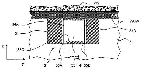
FIGS. 4, 5, 6 and 7 schematically show an antenna 3 according to different
embodiments of the invention. The antenna 3 that will be described hereinafter
according to the different embodiments may be used as a transmitting antenna
(e.g. the
transmitting antennas Tu, Td of FIGS. 2 and 3) or as a receiving antenna (e.g.
the
receiving antennas Ru, Rd of FIGS. 2 and 3).
In FIGS. 4, 6 and 7, the antenna is shown fitted into the pad 2, while the pad
contacts
the well-bore wall WBW. Typically, as in this example, the medium which is
investigated
consists in the formation GF covered by a mudcake MC. The mudcake MC is formed
on
the wellbore wall WBW by the screening of the particles of mud suspended into
the fluid
mixture when the fluid mixture invades the formation GF.
The antenna 3 comprises a conductive base 31 and a first antenna element 32.
The
conductive base 31 comprises an open, non-resonant cavity 33.
The cavity 33 has a elliptical or a cylindrical shape. Nevertheless, the
cavity 33 may
have other shapes, for example a parallelepipedic shape (not shown). As
example, the
aperture size a defined by such a cavity may be around 10 mm. Advantageously,
the
cavity is filled with a dielectric material. Any dielectric material may be
used as the
dielectric constant of said material filling the cavity has no impact on the
radiation purity.
Alternatively, an element in a ferrite material (not shown) may be inserted
into the
cavity. The ferrite material increases the magnetic dipole moment, while not
changing
the electric dipole moment.
The antenna element 32 goes right through the cavity while not contacting the
cavity
walls. The antenna element 32 is coupled to the electronic arrangement 4 by
means of
a first 34A and second 34B port. The port comprises a connection wire.
Advantageously, the antenna element 32 is coupled at the first 34A and second
34B
port at each of its ends. Advantageously, the couplings between each of the
two ports
and the electronic arrangement have the same length.
Advantageously, the antenna element 32 is positioned closed to the cavity 33
opening,
while not protruding outside the cavity because the pad may be move against
the well
bore wall during logging operation. Advantageously, the antenna element 32 is
in
CA 02683987 2009-10-15
WO 2008/125270 10
PCT/EP2008/002827
contact with the geological formation when the pad 2 is deployed against the
borehole
wall. However, in certain application, it may be advantageous that the cavity
is closed
by a cover or window (not shown) in order to retain and protect the dielectric
material.
Advantageously, the cover is made of a protective material, resistant to
abrasion, for
example PEEK (thermoplastic PolyEtherEtherKeton). However, any other material
that
does not perturb high-frequency-wave propagation and shows an appropriate
mechanical resistance to abrasion is acceptable.
The antenna element 32 may have a strip shape. As an example, the width of the
strip
is around 5 mm. The resistance against abrasion, the electric dipole moment,
and the
sensitivity (in particular sensitivity in reflection in a substantially pure
electrical dipole
mode EDM) may be improved by increasing the width of the strip.
In the example of FIG. 3, the antennas are oriented such that each antenna
element 32
is perpendicular to the pad axis, thus perpendicular to the borehole axis.
This
corresponds to a preferred configuration in which the magnetic dipole is
parallel to the
pad axis AA'. This configuration enables deeper measurements in the geological
formations. However, in certain application, it may be interesting that the
antennas are
oriented such that the antenna element is in alignment with the pad axis, thus
parallel to
the borehole axis (such a configuration is not shown in the drawings).
FIGS. 4 and 5 illustrate the antenna 3 according to a first embodiment.
The first 34A and second 34B ports pass through the conductive base 31 by
means of
first 35A and second 35B openings. The openings 35A, 35B are positioned into
the
bottom 33C of the cavity straight underneath the antenna element ends. The
first 34A
and second 34B ports extend into the cavity 33. Advantageously, the ports 34A,
34B
are insulated relatively to the conductive base at least when passing through
the
openings. As an alternative, the openings 35A, 35B are filled with an
insulating material
in order to insulate the connection wires of the ports relatively to the
conductive base
and maintain the positioning of the antenna element 32 into the cavity 33.
FIG. 6 illustrates the antenna 3 according to a second embodiment. The first
34A and
second 34B ports pass through the conductive base 31 by means of first 36A and
second 36B inversed L-shaped tunnels. The tunnels extend from the bottom of
the
conductive base 31 and emerge into the cavity 33 by the lateral walls 33A, 33B
close to
the top of the cavity. The antenna element 32 extends all along the cavity
aperture. As
illustrated in FIG. 6, the antenna element 32 may also extends into a portion
of the first
CA 02683987 2009-10-15
WO 2008/125270 11
PCT/EP2008/002827
36A and second 36B tunnels. The first 34A and second 34B ports extend into the
first
36A and second 36B tunnels. Advantageously, the ports 34A, 34B are insulated
relatively to the conductive base 31 all along the tunnels 35A, 35B. Further,
the ends of
the antenna element 32 when extending into the portion of the first 35A and
second 35B
tunnels are also insulated relatively to the conductive base 31.
FIG. 7 illustrates the antenna 3 according to a third embodiment. The third
embodiment
differs from the first one in that the first 35A and second 35B openings
positioned into
the bottom of the cavity 33 are replaced by a unique opening 37. The unique
opening
37 is positioned substantially at the center of the bottom 33C of the cavity
33.
Advantageously, the ports 34A, 34B are insulated relatively to the conductive
base and
relatively to each other at least when passing through the openings.
In the various embodiments, the metallic parts of the antenna may be gold-
plated in
order to minimize Ohmic losses. The antenna 3 may be designed under the form
of an
antenna module inserted into a slot of the pad 2. In this case, the conductive
base 31
may advantageously comprise a printed-circuit board (not shown) coupled to the
antenna element 32 by means of the port 34A, 34B. The printed-circuit board
may
comprise an impedance-matching network. The impedance-matching network enables
maximizing the power transmitted into the formation when the antenna is a
transmitter,
or, by reciprocity, the power received when the antenna is a receiver.
Advantageously,
the printed circuit board and the impedance-matching network are located
closely to the
antenna element in order to improve its efficiency. For example, the printed-
circuit board
may be located at a distance inferior to a size of the cavity from the antenna
element.
Finally, the matching network may be designed for several discrete frequencies
with
passive components (inductances or capacitances) or active components
(variable
capacitance). The active components enable operating in a frequency range from
0.01 GHz to 2.0 GHz with a maximized efficiency.
In FIGS. 8, 9, 10, 11 and 12, the receiving R and transmitting T antenna are
identical to
antenna 3 described hereinbefore with relation to FIG. 4-7. In FIGS. 8 and 9,
a circle
represents an electric dipole, while an arrow represents a magnetic dipole.
The electric
dipole is oriented perpendicularly to the plan defined by the cavity opening
of the
antenna. The magnetic dipole is parallel to the plan defined by the cavity
opening of the
antenna.
CA 02683987 2009-10-15
WO 2008/125270 12
PCT/EP2008/002827
FIGS. 8 and 10 are a top view and a cross-section view schematically showing a
transmitting antenna T, respectively. FIG. 10 further schematically
illustrates a part of
the electronic module 4. The ports TA, TB of the antenna element used as a
transmitter
T are coupled to a transmitter module 44T. As an example, the transmitter
module 44T
comprises two power amplifiers 45A and 45B. The output of the first amplifier
45A is
connected to the first port TA while the output of the second amplifier 45B is
connected
to the second ports TB of the antenna used as a transmitter T. Thus, a port
dependent
voltage may be applied to each end of the antenna. With such a transmitter
module
44T, the antenna may be operated so as to define a superposed pure magnetic
dipole
and pure electric dipole.
FIGS. 9 and 11 are a top view and a cross-section view schematically showing a
receiving antenna R, respectively. FIG. 11 further schematically illustrates a
part of the
electronic module 4. The ports RA, RB of the antenna element used as a
receiver R are
coupled to a receiver module 44R. As an example, the receiver module 44R
comprises
two low noise amplifiers 46A and 46B. The input of the first amplifier 46A is
connected
to the first port RA while the input of the second amplifier 46B is connected
to the
second ports RB of the antenna used as a receiver R. Thus, a port dependent
voltage
may be measured to each end of the antenna. With such a receiver module 44R,
the
antenna is operated so as to define a superposed pure magnetic dipole and pure
electric dipole.
FIG. 12 schematically shows the electronic module 4. The transmitter 44T and
receiver
44R modules are coupled to a control and processing module 43. The control and
processing module 43 commands the operation of the transmitting T and
receiving R
antenna. The calculation performed by the control and processing module 43
based on
the measurements provided by the receiver will be described hereinafter.
With the antenna of the invention and the above described transmitter,
receiver, and
control and processing modules, the electric dipole mode (EDM) and the
magnetic
dipole mode (MDM) are excited simultaneously and separated mathematically.
Preferably, the impedances on the two ports for each antenna should be very
close.
CA 02683987 2009-10-15
WO 2008/125270 13
PCT/EP2008/002827
With the transmitter module of the invention and for a suitable load
impedance, the
antenna will behave as the superposition of a pure magnetic dipole and a pure
electric
dipole, with a current distribution given by:
J(y) = Jo cos(k 0 [y ¨ ¨al + cp)
2
where:
- J0 is the current amplitude,
- a is the aperture size,
- 1(0 is the wave number in the cavity and is equal to: ko
¨C Al cavzty
- Ecavity is the relative dielectric constant of the material filling the
cavity,
- w is the angular frequency,
- c is the speed of light in vacuum, and
- cp is a phase depending on the load impedance.
According to a first alternative, the control and processing module 43
activates the
transmitting module such that the first port TA and the second port TB of the
transmitting antenna are activated sequentially, i.e. port TA and then port TB
or
conversely. In this alternative, the frequency of the signal exciting the
transmitting
antenna via the first and second ports may be the same, for example 1 GHz. The
receiving antenna and the receiving module receive the signals on the two
ports RA, RB
simultaneously.
According to a second alternative, the control and processing module 43
activates the
transmitting module such that the first port TA and the second port TB of the
transmitting antenna are activated simultaneously. In this alternative, the
frequency of
the signal exciting the transmitting antenna via the first and second ports
must be
different, for example the first port TA is excited by a signal having a
frequency of
1 GHz, while the second port TB is excited by a signal having a frequency of
1 GHz+10 kHz. The receiving antenna and the receiving module receive the
signals on
the two ports RA, RB simultaneously. The difference in frequency enables the
control
and processing module 43 distinguishing between the received signals resulting
from
the excitation of the first port TA relatively to the second port TB.
CA 02683987 2009-10-15
WO 2008/125270 14
PCT/EP2008/002827
Four signals can be obtained from the different combinations: transmitter
ports TA or TB
and receiver ports RA and RB.
These signals depend on the combined antenna and electronic elements gain a,
the
electric dipole length of the transmitter tr and the receiver tR, the magnetic
dipole area
of the transmitter ST and the receiver SR, and the medium.
It is assumed that the transmitter antenna and the receiver antenna can be
different and
that in an antenna, the ports A and B are mechanically symmetrical and have
the same
load impedance:
XT = XTA = XTB
{
XR = XRA = XRB
ST = STA = STB
SR = SRA = SRB
The influence of the medium may be expressed with a first function fEDm
corresponding
to antennas operating in a pure electric dipole mode and fmDm corresponding to
antennas operating in a pure magnetic dipole mode. Both functions depend on
the wave
number k and the distance between the antennas r.
These signals can be written as:
VTA-RA = a TA a XRA T XR fEDm (kyr) arAaRASTSRfmDm(k,r)
VTA-RB = a TA a RB XT XR f EDM (k, r) ¨ ancERBSTSRfmDm (k,r)
VTB-RA = a TB a RA TX XR f EDm (k,r)¨ a-ma RASTSRfmDm (Kr)
VTB-RB = a TB a RB XT XRfEDM k( ,r) OC TBa RB STSR fmDm (k, r )
where:
e !kr
fmDm (k, r) is proportional to __ (1 ikr), and
27cr'
eikr /
fEDm (k, r ) is proportional to ___________ 0 ikr ¨ k 21.2 )
470.3
By combining these data, the signals related to the pure electric dipole VEDm
and the
pure magnetic dipole VmDm can be extracted and rendered only dependent on the
function f and the gain G of the transmitting and receiving antennas:
V EDM = AIVTA_RA X VTB_RB V VTA_RB X VTB_RA
= 2-jama RAama RR x XTX R x f Rpm (k,r), and
= G ET Dm X G ER Dm
x ., f EDM (k, r)
Vmak, = NIVTA_RA X VTB RB ¨ VVTA_RB X VTB_RA
= 2.,,i I a TAa RAaTBa RB x ST SR x
fm-DA4 (k,r)
= G AdT Dm X G AIR DA, x LIDA,' (k, r)
CA 02683987 2009-10-15
WO 2008/125270 15
PCT/EP2008/002827
Then, a known borehole compensation method can then be applied. The borehole
compensation method enables eliminating the gains of the receiving antennas
that may
be slightly different. For example, an electromagnetic logging apparatus
comprising a
set of four antennas is considered, namely the configuration shown in FIGS. 2
and 3
with two transmitting antennas Tu, Td and two receiving antennas Ru, Rd. Each
antenna
having two ports A and B, this configuration enables obtaining 16 signals.
Then, the
above formulae become:
V EDM (Tu ' Rd) = G ET'DM
{
V EDM (Td , Ru) = X Gm X f EDm (k,r1)
VEDM (Tu , Rd) =
G ET"DA,/ X G ERAw X f EDM ( k,r2)
GEraDm x GERbm f
GETaDm xGERL m f
x a EDM (k,r21
x , EDM 0 C 111)
\,
VEDm(Td , Rd) = and
VmDm (Tu , Ru) = G7A,.;Dm X G mR.Dm x fmDm (k,r1)
V mDm (Tu , R d) = Gi1mDm X GRd (
mavi x fmDivi k, r2)
VmDm (Td , R u) = G L' Dm X G mR,Dm X fmDm (k , 1'2)
VmDm (Td , Rd) = G 171;; Dm X G mRdDm X fivitim QC, r1)
These signals can be combined and related to the measured attenuation AT and
phase-
shift PS:
I , V E (Tu R ) V (T Ru
EDM EDM l
AT ¨ iPS = ln DM d x EDM d ,
ss:1, V EDm (Tu , Ru) VEDm (Td , Rd)
I __________________________________________________ \
=ln
GM X GRa X fEDM (k' r2 ) x GM rd x GM R. x fEDM Oc, r2 ,) and
ED EDM
A G ETuDA4 x GMX fEDM OC, rl ) GM X GAM X fEDxf (k, /I )
\ / 17
I ____________________________________________
AT ¨ .PS ¨1 n AIVMDM(u 9 Rd) xVMDM(Td , Ru)
1NDM MDM ¨
\ VMDMVu, Ru) VMDM(Td , Rd)
r \
G kir Dm
= X GmRaDm X fmDm (k, r2) Gr:ItDm x GLuDA,, x fmDm (k,r2)
In ____________________________ x
,\ Glm x GmR.Dõ,, x fmDA4 (k,r1) GmTaDm X GmRaDm X fmDm (k,r1) )
This expression can be reduced to expression that only depends on the
functions f and
not anymore on the gain G, namely:
(k r
ATEDM ¨iPSEDM = ln f EDM) i ' 2 \ , and
fEDm kk, ri i
CA 02683987 2009-10-15
WO 2008/125270 16
PCT/EP2008/002827
AT'PS ¨1 [fmDm(k' r2 ))
MDM - 1 MDM ¨ n r (1, 1
J MDM ln' 1 11 i
Thus, by measuring the attenuation AT and phase-shift PS of the signals at the
receiving antennas relatively to the transmitting antennas operated according
to a
superposed pure magnetic dipole and pure electric dipole mode, it is possible
to
mathematically separate the contribution of each mode and to determine the
electromagnetic properties of the medium by means of a simple mathematical
inversion
operation.
The top graphic of FIG. 13 shows four curves representing the amplitude A of
the
different signals measured at the port of a receiving antenna. The bottom
graphic of
FIG. 13 also shows curves representing the phase P of the different signals
measured
at the port of a receiving antenna. These measurements have been obtained with
an
electromagnetic logging apparatus comprising a set of three antennas, a first
Tu and a
second Td transmitting antenna and one receiving antenna R spaced apart from
the
transmitting antennas. Each antenna has two ports A and B. In this particular
configuration, only port A of the transmitting antennas have been excited. The
signals
shown are:
TdARA representing the signal received on port A of the receiving antenna R
caused by
the excitation of port A of the downside transmitting antenna Td;
TdARB representing the signal received on port B of the receiving antenna R
caused by
the excitation of port A of the downside transmitting antenna Td;
TuARA representing the signal received on port A of the receiving antenna R
caused by
the excitation of port A of the upside transmitting antenna Tu; and
TuARB representing the signal received on port B of the receiving antenna R
caused by
the excitation of port A of the upside transmitting antenna Tu.
The same curves can be obtained with an ideal configuration based on the
configuration
shown in FIGS. 2 and 3 with two transmitting antennas Tu, Td and two receiving
antennas Ru, Rd where all the antennas are identical, namely:
TdAIRA= TdAR A
u= T B B
rd T A A=
uRd T B
uRdB ;
TdARB= TdARuB= TdBRuA= TuARdB= TuBRdA ;
TuR= T A
uR A
u= T B
uR g A A E3
u= TdRd= Td Rd
AA B, and
T AB
uR= T A g
uRu= T g A A B B
uRu= TdRd= TdRdA=
CA 02683987 2009-10-15
WO 2008/125270 17
PCT/EP2008/002827
The external medium is characterized by a permittivity c=15 and a conductivity
cy=0.2 S/m. The distance between the two transmitting antennas is 25 mm. The
distance
between the first transmitting antenna Tu and the receiving antenna R is 37.5
mm.
By combining the above mentioned measurements, two attenuation values AT (EDM
and MDM) and two phase-shift values PS can be determined. These values can be
compared to theoretical ones.
The theoretical values of the attenuation AT and phase-shift PS may be
calculated with
the following formulae which assume a homogeneous medium and no mudcake onto
the borehole wall.
For the magnetic dipole mode (MDM), the theoretical values are given by:
ATMDM ¨ iPSMDM ¨ 314¨r2)+ik(ri ¨ r2)+ 141¨ ikr2 )
¨ r 1¨ ikr,
1
For the electric dipole mode (EDM), the theoretical values are given by:
( 11
A TEDAd ¨ iPS Eaki = 31n r2 + ik(ri ¨ r2)+ in
1 i ¨ikr2¨k2 2
r2
r
1¨ikri ¨k2r12 j
where:
- r1 and r2 are the distances between transmitters and receivers,
- the wave number k is given by:
CO,k Viir
=¨ e+iolcoso ,
c
- c is the relative medium permittivity,
- cr is the medium conductivity, and
- fir is the relative magnetic permeability (typically equal to 1 for
logging application).
FIG. 14 represents graphic showing curves representing the attenuation AT
measured
(dotted line curve) with an antenna according to the invention compared to
theoretical
values (plain line curve) as a function of the frequency for the electric
dipole mode
(EDM) and the magnetic dipole mode (MDM). FIG. 15 represents graphic showing
curves representing the phase-shift PS measured (dotted line curve) with an
antenna
according to the invention compared to theoretical values (plain line curve)
as a function
of the frequency for the electric dipole mode (EDM) and the magnetic dipole
mode
(MDM).
It is observed that with the antenna of the invention combined with the
appropriate
electronic elements and the above described calculation method, an excellent
agreement is obtained between measured values and theoretical values.
CA 02683987 2015-06-02
18
The combination of an antenna element having a simple design coupled to an
appropriate
electronic circuit enables operating the antenna according to a superposition
of a pure
magnetic dipole and a pure electric dipole mode, and further mathematically
separating the
contribution of the magnetic dipole mode and the electric dipole mode. The
measurement
contribution related to the magnetic dipole mode (MDM) enables a deep radial
depth of
investigation into the formation. The measurement contribution related to the
electric dipole
mode (EDM) enables a shallow radial depth of investigation into the formation
or into the
mudcake when present on the borehole wall.
Based on the attenuation and phase-shift measurements, the permittivity E and
the
conductivity a of the formation can be calculated by means of a known
inversion calculation.
The antennas of the invention are comprised in an electromagnetic logging
apparatus (see
FIG. 1). The electromagnetic logging apparatus can implement a method to
determine the
electromagnetic properties of the medium surrounding the borehole. The
structure and
operation of such an electromagnetic logging apparatus is described in details
in the patent
application published under No EP 1 693 685 (filed on 22 February 2005). The
electromagnetic probe of the present invention differs from the one of EP 1
693 685 in that it
comprises the antennas of the invention as hereinbefore described.
While the logging apparatus is being run through the borehole and the pad
engaged with
the borehole wall (FIG. 1), electromagnetic signals are radiated into the
formation
surrounding the borehole by the transmitting antennas Tu, Td. The attenuation
and phase-
shift of the electromagnetic signals are measured by means of the receiving
antennas Ru,
Rd.
A method of investigation using the antennas of the invention will now be
described in
relation with FIG. 16. In a first step (S1), the logging apparatus is run
through the borehole
and a pad is engaged with a borehole wall so as to define a selected zone SZ
made of a
medium to be investigated (see FIGS. 1 and 2).
In a second step (S2), the antennas are operated by activating a first port of
the transmitting
antenna (for example TA - see FIGS. 8 and 10) so that each antenna defines a
superposed
pure magnetic dipole and pure electric dipole. As a consequence,
electromagnetic signals
are radiated in the medium. Simultaneously, a first set of
CA 02683987 2009-10-15
WO 2008/125270 19
PCT/EP2008/002827
measurements is performed comprising measuring a first and a second sub-set of
attenuation and phase shift of the electromagnetic signals having traveled in
the
medium between the transmitting and receiving antennas at a first port (RA)
and a
second port (RB) of the receiving antenna (see FIGS. 9 and 11), respectively.
In a third step (S3), the antennas are operated by activating a second port of
the
transmitting antenna (for example TB - see FIGS. 8 and 10) so that each
antenna
defines a superposed pure magnetic dipole and pure electric dipole. As a
consequence,
electromagnetic signals are radiated in the medium. Simultaneously, a second
set of
measurements is performed comprising measuring a third and a fourth sub-set of
attenuation and phase shift of the electromagnetic signals having traveled in
the
medium between the transmitting and receiving antennas at a first port and a
second
port of the receiving antenna (see FIGS. 9 and 11), respectively.
In a fourth step (S4), calculation can be performed based on the first,
second, third and
fourth sub-set measurement of attenuation and phase shift. These measurements
are
combined and a first contribution due to the pure magnetic dipole (MDM) and a
second
contribution due to the pure electric dipole (EDM) are extracted. With these
measurements, it is now possible in a fifth step (S5) to determine the
permittivity e and
the conductivity a of the medium in the selected zone by means of an inversion
calculation as hereinbefore described.
The first set of measurements (step S2) and the second set of measurements
(step S3)
may be performed sequentially. In this case, the first (TA) and second (TB)
ports are
preferably activated by electrical signals having identical frequencies.
The first set of measurements (step S2) and the second set of measurements
(step S3)
may also be performed simultaneously. In this case, the first (TA) and second
(TB) ports
are preferably activated by electrical signals having different frequencies.
Advantageously, in electromagnetic logging apparatus comprising at least two
transmitting antennas Tu, Td and at least two receiving antennas Ru, Rd
(configuration
shown in FIGS. 2 and 3), differential measurements between the attenuation and
phase
shift measured at the ports of the at least two receiving antennas can be
performed and
a borehole compensation scheme can be applied. As illustrated in the
hereinbefore
formulae, this enables eliminating each antenna gain from the calculation of
the medium
properties.
FINAL REMARKS
CA 02683987 2009-10-15
WO 2008/125270 20
PCT/EP2008/002827
A particular application of the invention relating to a wireline tool has been
described.
However, it is apparent for a person skilled in the art that the invention is
also applicable
to a logging-while-drilling tool. A typical logging-while-drilling tool is
incorporated into a
bottom-hole assembly attached to the end of a drill string with a drill bit
attached at the
extreme end thereof. Measurements can be made either when the drill string is
stationary or rotating. In the latter case an additional measurement is made
to allow the
measurements to be related to the rotational position of the drill string in
the borehole.
This is preferably done by making simultaneous measurements of the direction
of the
earth's magnetic field with a compass, which can be related to a reference
measurement made when the drill string is stationary.
It will also be apparent for a person skilled in the art that the invention is
applicable to
onshore and offshore hydrocarbon well location.
It is apparent that the term "pad" used hereinbefore generically indicates a
contacting
element with the surface of the borehole wall. The particular contacting
element shown
in the Figures for maintaining the antennas in engagement with the borehole
wall is
illustrative and it will be apparent for a person skilled in the art that
other suitable
contacting element may be implemented, for example a sonde with a backup arm,
a
centralizer, etc....
The same remark is also applicable to the particular probe deploying system
shown on
the Figures.
Finally, it is also apparent for a person skilled in the art that application
of the invention
to the oilfield industry is not limited as the invention can also be used in
others types of
geological surveys.
The drawings and their description illustrate rather than limit the invention.
Any reference sign in a claim should not be construed as limiting the claim.
The word
"comprising" does not exclude the presence of other elements than those listed
in a
claim. The word "a" or "an" preceding an element does not exclude the presence
of a
plurality of such element.