Note: Descriptions are shown in the official language in which they were submitted.
CA 02684120 2009-10-28
AUGER BIT WITH INTERLOCKING FEED SCREW AND CUTTING INSERT
BACKGROUND OF THE INVENTION
Auger bits have been used to drill holes in utility poles made of wood for a
number of
years. These auger bits usually have a feed screw near their tip that helps
propel the bit through a
pole, at least one cutting edge located below the feed screw near the outer
circumference of the
main shaft of the auger bit that enables the auger bit to cut through the
wood, a main shaft with a
generally cylindrical shape that has at least one flute that extends from the
cutting edge and
allows chips formed by the auger bit as it bores into a pole to be removed
from the cutting site,
and a shank portion that has a diameter that is less than the main shaft that
extends from the
bottom of the main shaft of the auger bit.
The shank portion typically has three flats milled about its periphery which
allow it to be
easily held in a chuck of a powered drill or impact wrench which can be used
by the user to cause
the auger bit as a whole to rotate. As the auger bit rotates, the threads of
the feed screw help to
propel the auger bit through the pole, making it easier for the user to
complete the boring
operation. At the same time, the cutting edges remove material as the auger
bit rotates and send
this material along the flute of the bit, allowing deep holes to be bored.
When being used in the field, it is common for an auger bit to hit nails that
are within
the wooden pole. This can cause damage to the feed screw and cutting edges,
impairing the
function of the auger bit. For example, the threads of the feed screw could be
deformed which
prevents the auger bit from self feeding through the pole as it rotates,
requiring the user to push
and work harder to bore a hole. Likewise, the cutting edges can become chipped
or dulled so that
they do not efficiently remove wood chips making boring slow. Consequently, a
number of
techniques have been developed to remedy these problems.
For example, United States Patent No. 1,389,578 discloses an auger bit that
has a
replaceable insert that has the feed screw and cutting edges incorporated
therein. The replaceable
insert can be attached to the shaft of the auger bit using a single screw.
This design, however,
has two disadvantages. First, the manufacturing the insert is difficult and
costly because of the
configuration of the replaceable insert because it includes both the feed
screw and cutting edges.
1
CA 02684120 2009-10-28
Second, both the feed screw and the cutting edges are replaced regardless of
what features have
been damaged on the auger bit, forcing thc user to buy and use a replacement
insert that is often
more costly than necessary.
United States Patent No. 5,820,319 discloses an auger bit that has replaceable
feed screw
that is attached to the shaft by means of a single screw. This technique,
however, does not
provide for any way to replace worn cutting edges. Therefore, this auger bit
does not allow the
user to handle situations when the cutting edge has become dull. Conversely,
United States
Patent No. 6,024,520 discloses replacing cutting edges using a screw to attach
the replaceable
cutting insert to the shaft, but provides no means to replace the feed screw.
Thus, neither United
States Patent No. 5,820,319 nor United States Patent No. 6,024,520 provides a
suitable way to
replace both feed screw and cutting inserts, giving the user the needed
flexibility to address problems in the field.
Finally, United States Patent Nos. 4,625,593 and 6,361,255 disclose
replaceable feed
screws and cutting inserts, but neither show how they can be attached in a
quick and effective
manner. United States Patent No. 4,625,593 discloses that the insert is brazed
onto the shaft
making replacement difficult, while United States Patent No. 6,361,255 fails
to specify the exact
means by which the feed screw and cutting insert are attached in a replaceable
manner to the
shaft of the auger bit.
Accordingly, there exists a need for an auger bit that has a replaceable feed
screw and a
replaceable cutting insert that can be attached in a quick manner, and that
allows the user to
select which feature needs to be replaced in a cost effective way.
BRIEF DESCRIPTION OF THE DRAWINGS
The organization and manner of the structure and operation of the invention,
together
with further objects and advantages thereof, may best be understood by
reference to the following
description, taken in connection with the, accompanying drawings, wherein like
reference
numerals identify like elements in which:
FIG. 1 is perspective view of an auger bit which includes a shaft, an insert
and a feed
screw, which incorporates the features of the present invention;
2
CA 02684120 2009-10-28
FIG. 2 is a side elevational view of the auger bit;
FIG. 3 is an alternate side elevational view of the auger bit;
FIG. 4 is a perspective view of a shaft of the auger bit;
FIG. 5 is a side elevational view of the shaft;
FIG. 6 is a cross-sectional view of the shaft along line 6-6 of FIG. 5;
FIG. 7 is an alternate side elevational view of the shaft;
FIG. 8 is a cross-sectional view of the shaft along line 8-8 of FIG. 7;
FIG. 9 is a cross-sectional view of the shaft along line 9-9 of FIG. 7;
FIG. 10 is an end plan view of the shaft;
FIG. 11 is a view of the shaft along the view of line 11-11 in FIG. 10;
FIG. 12 is a cross-sectional view of the shaft along line 12-12 of FIG. 10;
FIG. 13 is a side elevational view of the feed screw;
FIG. 14 is an alternate side elevational view of the feed screw;
FIG. 15 is a side elevational view of the insert;
FIG. 16 is a view of the insert along the view of line 16-16 in FIG. 15;
FIG. 17 is an end plan view of the insert; and
FIG. 18 is an alternate side elevational view of the insert.
SUMMARY OF THE INVENTION
Briefly, the present invention discloses an auger bit which includes a shaft
having a
central axis, a cutting insert mounted to said shaft, and a feed screw that is
separate from the
cutting insert and which is mounted to the shaft. The cutting insert and the
feed screw are
engaged with each other. A single locking member, such as a set screw, secures
the feed screw
member to the shaft, and thereby secures the cutting insert to the shaft. If
the feed screw or the
cutting insert become worn, feed screw or the cutting insert can be replaced.
3
CA 02684120 2009-10-28
DETAILED DESCRIPTION OF THE PREFERRED EMBODIMENT
While the invention may be susceptible to embodiment in different forms, there
is shown
in the drawings, and herein will be described in detail, a specific embodiment
with the
understanding that the present disclosure is to be considered an
exemplification of the principles
of the invention, and is not intended to limit the invention to that as
illustrated and described
herein.
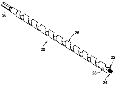
FIGS. 1-3 shows an auger bit 20 that has a replaceable cutting insert 22 and a
replaceable
feed screw 24 attached to a shaft 26 of the auger bit. The cutting insert 22
and the feed screw 24
are attached to the shaft 26 using a single set screw 28.
The shaft 26 has a continuous land 30 and flute 32 which extends from a
leading end 34
of the shaft 26 to a shank 36 which is provided at a trailing end 38 of the
shaft 26. A central axis
39 extends along the length of the shaft 26 from the leading end 34 to the
rearmost end of the
shank 36. The outer periphery of the land 30 is formed as a cutting edge. A
groove 40 extends
from the cutting insert 22 to the trailing end 36 and allows the removal of
chips as the auger bit
20 bores a hole. The shaft 26 has first, second and third passageways first
passageway 42, 44, 46
proximate to its leading end 34 that allow the cutting insert 22, the feed
screw 24 and the set
screw 28 to be inserted into the shaft 26. In addition, a fourth passageway 48
is provided
proximate to the leading end 34 of the shaft to allow a user to place an
implement within the
fourth passageway 50 to force the cutting insert 22 out of the shaft 26 when
desired.
The shank 36 has a smaller diameter than the shaft 26. The shank 36 has flats
52 thereon
which are held in a chuck of a powered drill or impact wrench which can be
used by the user to
cause the auger bit 20 as a whole to rotate.
The first passageway 42 forms the passageway into which the cutting insert 22
is
mounted. The wall which forms the second passageway 44 is smooth. The first
passageway 42
has a central axis 54 that intersects near the edge that would be formed by
the leading end 34 and
the circumference of the shaft 26. The central axis 54 forms an acute angle
with the central axis
39 of the shaft 26. Preferably, the acute angle is forty-five degrees which
prevents any thin areas
that could occur near the leading end 34 of the shaft 26 if the angle were
greater, such as ninety
degrees. The first passageway 42 terminates at a predetermined distance into
the shaft 26 at a
4
CA 02684120 2009-10-28
floor or stop surface 56. The depth of the first passageway 42 is great enough
so that the first
passageway 42 passes through the central axis 39 of the shaft 26.
The second passageway 44 forms the passageway into which the feed screw 24 is
mounted. The wall which forms the second passageway 44 is generally
cylindrical and smooth.
The second passageway 44 extends from the leading end 34 of the shaft 26
rearwardly coincident
with the central axis 39 of the shaft 26 a predetermined depth.
The third passageway 46 forms the passageway into which the set screw 28 is
mounted.
The third passageway 46 is located on the circumference of the shaft 26 at a
predetermined
distance from the leading end 34. The third passageway 46 has a central axis
58 that is
perpendicular to the central axis 39 of the shaft 26 and intersects the second
passageway 44.
Unlike the first and second passageways 42, 44 which have smooth walls, the
third passageway
46 has an internal thread thereon, such as a 1/4-28 internal thread so it can
mate with the set
screw 28 as fully described herein. The positioning of the third passageway 46
is chosen to make
sure that it is not too close to the groove 40 of the shaft 26, which could
compromise the
15. structural integrity of the third passageway 46.
The fourth passageway 48 is concentric with the first passageway 42 and
extends from
the stop surface 56 to the other side of the shaft 26. The fourth passageway
48 has a smaller
diameter than the first passageway 42. The wall which forms the fourth
passageway 48 is
smooth.
The shaft 26 with these features can be made from 1144 stress proof round
stock on a
multi-tasking lathe such that the outer dimensions are tuned, the passageways
42, 44, 46, 48 are
bored or drilled, and the flats 52 are milled. Finally, the groove 40 is
milled into the shank 34
using a whirler machine. Since the stock is pre-hardened, no further heat
treatment is required.
FIGS. 13 and 14 illustrate the construction of the feed screw 24. The feed
screw 24
includes a generally conical portion 60 on one end that has male threads
thereon. Extending
from threaded portion 60 is a stem 62 having a cylindrical shape and a
diameter that is less than
the threaded portion 60 creating an annular shoulder 64 at the bottom of the
threaded portion 60.
The stem 62 has a flat surface 66 proximate to its rear end that forms an
acute angle, such as five
degrees, with respect to a central axis 68 of the stem portion 62, such that
the depth of the
5
CA 02684120 2009-10-28
depression created by the flat surface 66 is deepest near the threaded portion
60 and decreases as
the flat surface 66 nears the rear end of the stem 62. The stem 62 is mounted
into the second
passageway 44. This construction helps to retain the feed screw 24 within the
shaft 26 as
described herein. The rear end of the feed screw 24 has a taper 70 that
facilitates assembly of the
auger bit 20 as will be more fully herein. The feed screw 24 can be
manufactured by a cold
headed blanking operation out of medium carbon steel to produce the overall
shape. Next, the
threads can be rolled onto its conical portion 60 and the flat surface 66 can
then be milled or
ground onto the stem 62. Finally, the feed screw 24 can be heat treated to
forty-five to fifty-five
Rockwell scale C.
FIGS. 15-18 show the cutting insert 22. The cutting insert 22 includes a
generally
cylindrical body 72 having first and second ends and a central axis 74. Three
flats 76a, 76b, 76c
that form cutting edges 78a, 78b, 78c are formed at one end of the generally
cylindrical body 72.
The generally cylindrical body 72 has a shape that corresponds to the first
passageway 42 in the
shaft 26. A groove 80 is formed in the generally cylindrical body 72 and has a
central axis 82
that forms a forty-five degree angle with the central axis 74 of the generally
cylindrical body 72.
The groove 80 mates with a portion of the feed screw 24 as described herein. A
chamfer 84 is
located around the perimeter of the second end of the generally cylindrical
body 72. The second
end forms an abutment surface 86. The cutting insert 22 can be manufactured
out of S-7 tool
steel using a screw machine or multi-tasking lathe, such that its general
shape is turned and the
flats 76a, 76b, 76c and groove 80 are milled thereon. The cutting insert 22 is
then heat treated to
a range of fifty to sixty Rockwell scale C.
The auger bit 20 can be assembled in the following manner. First, the user
inserts the
cutting insert 22 into the first passageway 42 with the abutment surface 86
facing the stop surface
56 of the first passageway 42 until the abutment surface 86 bottoms out on the
stop surface 56.
At this point, the cutting insert 22 is free to rotate within the first
passageway 42 arid the cutting
edges 78a, 78b, 78c are located near the edge defmed by the front end 34 and
the outer wall of
the shaft 26. Next, the user inserts the stem 62 of the feed screw 24 into the
second passageway
44 of the shaft 26 located on its front end 34 and pushes the feed screw 24
into the shaft 26 until
the taper 70 on the feed screw 24 contacts the cutting insert 22. At this
point, the groove 80 of
6
CA 02684120 2009-10-28
the cutting insert 22 is not necessarily aligned with second passageway 44 or
the stem 62 of the
feed screw 24, so the user usually must rotate the cutting insert 22 until the
edge of the groove 80
contacts the stem 62 of the feed screw 24. Once this happens, the user simply
pushes on the feed
screw 24 and the taper 70 will rotate the cutting insert 22 until the groove
80 is completely
aligned with the stem 62 of the feed screw 24. Once the annular shoulder 64
bottoms out on the
front end 34 of the shaft 26, the stem 62 has passed completely through the
groove 80 of the
cutting insert 22 and past the groove 80, thereby fixing the orientation of
the cutting insert 22 and
preventing the removal of the cutting insert 22 from the shaft 26.
The depth of second passageway 44 is greater than the length of the stem 52,
ensuring
that the feed screw 24 can be properly seated with no gaps between its
threaded portion 60 and
the front end 34 of the shaft 26. The depth of the first passageway 42 is
greater than the distance
from the groove 80 of the cutting insert 22 to its abutment surface 86,
ensuring that the groove 80
can properly align the stem 62 of the feed screw 24, while at the same time
the cutting edges 78a,
78b, 78c are located directly next to the groove 40 of the shaft 26 despite
any possible
dimensional variances due to manufacturing tolerances. The gap between the
abutment surface
86 of the cutting insert 22 and the stop surface 56 of the first passageway 42
of the shaft 26 is
small enough, e.g. a thirty second of an inch, to minimize the amount of
possible misalignment
between the groove 80 of the cutting insert 22 and the second passageway 44,
thereby easing
assembly. Once the cutting insert 22 and feed screw 24 have been installed,
the portions of the
cutting edges 78a, 78b, 78c that are nearest the tip of the feed screw 24 in a
direction that is
parallel to the central axis 39 of the shaft 26 extend past the last thread of
the feed screw 24,
helping to make sure that as the auger bit 20 passes through the pole it is
pulled through by the
threads of the feed screw 24 until the hole is complete, easing the drilling
operation.
The last step in assembling the auger bit 20 is to insert the set screw 28
whose external
threads match the internal threads of the third passageway 46 and tighten the
set screw 28 until it
approaches the stem 62 of the feed screw 24. The user must then rotate the
feed screw 24 so that
the flat surface 66 is aligned with the third passageway 46. Finally, the set
screw 28 is tightened
until it contacts the flat surface 66, which due to its angle, exerts some
force that urges the feed
screw 24 toward a fully seated position. This prevents the feed screw 24 from
being extracted
7
CA 02684120 2009-10-28
from the shaft 26 by the force created by land 30 as the land 30 engages a
workpiece or pole.
Disassembly of the auger bit 20 may be achieved by reversing the above
process.
Sometimes, debris or slight deformation may cause the removal of the cutting
insert 22 to be
difficult. Consequently, the fourth passageway 48 allows a user to insert an
implement, such as a
punch used with a hammer, to dislodge the cutting insert 22 forcibly.
As can be seen, the auger bit 20 provides an insert 22 and feed screw 24 that
can be
selectively replaced depending on what damage or dulling has occurred. The
auger bit 20 further
holds the insert 22 and feed screw 24 in place using a single locking member,
set screw 28.
Other locking members are within the scope of the present invention as would
be know to one of
ordinary skill in the art. Hence, this auger bit 20 satisfies the needs of an
auger bit 20 whose
features which are subject to wear can be replaced quickly and cost
effectively.
While a preferred embodiment of the present invention is shown and described,
it is
envisioned that those skilled in the art may devise various modifications of
the present invention
without departing from the spirit and scope of the appended claims.
8