Note: Descriptions are shown in the official language in which they were submitted.
CA 02684313 2009-11-04
VENDING APPARATUS
Field of the Invention
This invention relates to vending machines. In particular, this invention
relates to machines for vending articles.
Background of the Invention
Many different types of products are vended by vending machines.
Vendible products are of a variety of different shapes and sizes. One popular
example
of such vending machines is a so called "bulk vender," colloquially known as a
"gumball machine," which is typically designed to vend spherical articles such
as
gumballs but is also capable of vending articles having a generally spherical
or ovular
shape such as certain types of nuts, which are capable of being vended out of
a bulk
merchandise bin because the orientation of the product in the merchandise bin
does
not affect the dispensing mechanism. Such vending machines are typically
actuated
by a coin mechanism, which has a manually rotatable handle that is released
when a
coin or coins of the correct domination are inserted into a coin slot, as is
well known.
Other types of products, however, are not readily vended from a bulk
merchandise bin because of their shape. For example tubular products such as
cigars
and tampons are more difficult to vend, because the vending mechanism, in
order to
operate effectively, must be virtually guaranteed to receive at least one
article for
vending with each rotational cycle of the coin mechanism. Vending machines of
this
type are designed to be placed in unsupervised areas, and accordingly it is
essential in
order to promote repeated consumer use and reduce costs to the vending machine
operator that the vending machine consistently vend product when the correct
coinage
is inserted into the coin mechanism, and that the vending machine be very
resistant to
jamming due to misaligned or clustered product. This presents a particular
problem in
the vending of oblong products, such as cigars and tampons.
One manner of maintaining an article in a select orientation for dispensing
is by disposing a magazine in a vender. The magazine holds a plurality of
articles in a
stack, in a particular orientation, and can thus deliver an article to a
dispensing
mechanism in a desired orientation. However, it is advantageous to a vending
-1-
CA 02684313 2009-11-04
machine operator, who may be responsible for hundred of vending machines, to
have
to service each vending machine as infrequently as possible, and it is
therefore
advantageous to include as much merchandise as possible in the vending
machine.
However, disposing articles in a stack formation in a magazine limits the
number of
articles that can be dispensed by the vending machine, because there is a
practical
limitation on the height (or length) of such a vending machine which in turn
limits the
number of articles that can be contained in the stack.
Brief Description of the Drawings
In drawings which illustrate by way of example only a preferred
embodiment of the invention,
Figure 1 is a perspective view of a vending machine embodying the
invention;
Figure 2 is a partial front elevational view of the magazines and dispensing
drum in the vending machine of Figure 1, with all magazines containing
articles;
Figure 3 is a partial front elevational view of the magazines and dispensing
drum with articles depleted from the upstream magazine;
Figure 4 is a partial front elevational view of the magazines and dispensing
drum with articles depleted from two of the three magazines;
Figure 5 is an exploded view of the dispensing drum and drum carrier
showing a locking mechanism for arresting rotation of the dispensing drum in
the
preferred embodiment;
Figure 6 is a partial cross sectional side elevation of the vending machine
of Figure 1;
Figure 7 is a partial side elevation of the dispensing region showing a dog
for locking a door to the dispensing chute in a rest position;
Figure 8 is a partial side elevation of the dispensing portion of Figure 7
showing the dog in an engaged position; and
-2-
CA 02684313 2009-11-04
Figure 9 is a perspective view of the locking dog.
Detailed Description of the Invention
The invention provides a vending machine for vending articles,
comprising a rotatable dispensing drum comprising a wall comprising at least
one
recess sized to receive a single article, a mechanism for rotating the
dispensing drum
about a rotational cycle, a plurality of magazines, each magazine for
containing
articles in a stack, each magazine being in communication with the dispensing
drum
and disposed such that a proximate article in the magazine contacts the
dispensing
drum, the wall of the dispensing drum blocking the delivery of the proximate
article
from the magazine until an empty recess comes into alignment with the
proximate
article during rotation of the dispensing drum and the proximate article is
forced into
the recess, the proximate article in the recess blocking the delivery of any
other
proximate article into the recess, and a dispensing portion into which the
proximate
article in the recess is dispensed from the recess as the dispensing drum is
rotated
further along its rotational cycle.
The invention further provides a vending machine for vending articles,
comprising a rotatable dispensing drum comprising a wall comprising at least
one
recess sized to receive at least one article, a mechanism for rotating the
dispensing
drum about a rotational cycle, a plurality of magazines, each magazine for
containing
articles in a stack, each magazine being in communication with the dispensing
drum
and disposed such that at least one proximate article in the magazine contacts
the
dispensing drum, the wall of the dispensing drum blocking the delivery of the
at least
one proximate article from the magazine until an empty recess comes into
alignment
with the at least one proximate article during rotation of the dispensing drum
and the
at least one proximate article is forced into the recess, the at leastone
proximate article
in the recess blocking the delivery of any other proximate article into the
recess, and a
dispensing portion into which the at least one proximate article in the recess
is
dispensed from the recess as the dispensing drum is rotated further along its
rotational
cycle.
-3-
CA 02684313 2009-11-04
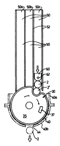
As illustrated in Figure 1, a vending machine 10 according to the invention
comprises a housing 12, for example formed from sheet metal, having an article
storage portion 14 which may conventionally be provided with a transparent
glass or
plastic window through which articles 2 can be viewed, and a secure dispensing
portion 16 contained within the housing which in the embodiment shown
comprises a
dispensing chute 18 allowing communication between the interior and the
exterior of
the housing 12.
A dispensing drum 30 is contained within the dispensing portion 16, for
example rotationally mounted in a drum holder 40, illustrated in Figures 4 and
5. The
dispensing drum 30 comprises at least one recess 32 sized to receive a single
article
contained within the article storage portion 14 of the housing 12. The
dispensing
drum 30 further comprises an axle 34 rotationally fixed to the wall 38 of the
dispensing drum 30, for example extending through and fixed to hub 35, and
providing a structure for keyed attachment, in the example shown a squared
portion
36 of the axle 34, to a mechanism for rotating the dispensing drum 30 about a
rotational cycle. The dispensing drum 30 is preferably formed from metal, for
example cast in zinc or aluminum, but may be formed from plastic or any other
suitable material.
In the vending machine shown the mechanism for rotating the dispensing
drum 30 about the rotational cycle comprises a coin mechanism 15. One suitable
coin
mechanism, referenced by way of example only because any suitable coin
mechanism
may be used without affecting the operation of the invention, can be found in
U.S.
Patent No. 5,383,545 issued January 24, 1995, which is incorporated herein by
reference. In other embodiments the mechanism for rotating the dispensing drum
30
need not be a coin mechanism, but can include any suitable mechanism such as a
simple crank, a loader, rack and pinion arrangement or any other mechanism
capable
of rotating the dispensing drum 30, and the invention is not intended to be so
limited.
As best illustrated in Figures 2 through 4, in order to maximize the number
of articles that can be contained within the storage portion 14 of the vending
machine
10, the invention provides a plurality of magazines 50a, 50b, 50c. Each
magazine 50
-4-
CA 02684313 2009-11-04
is formed from a sheet material, for example metal or plastic, and dimensioned
to
contain the article desired to be dispensed in a stack. In the preferred
embodiment
three magazines 50a, 50b and 50c are provided in side-by-side relation. It is
advantageous to arrange the magazines 50a, 50b, 50c in this fashion because a
single
magazine sidewall 52 can serve as a sidewall for adjacent magazines 50.
However, it
is possible to instead space the magazines 50 apart if desired.
An open end of each magazine 50 (the bottom end in the embodiment
illustrated) is in communication with the dispensing drum 30 and disposed such
that a
proximate article to 2' at the proximate end of the magazine 50 is blocked by
the
circumferential wall 38 of the dispensing drum 30 from being delivered out of
the
magazine 50. The magazines 50 are thus preferably disposed such that the ends
of the
magazines 50 that deliver articles 2 (the lower ends in the illustrations) are
adjacent to
one another and immediately adjacent to the dispensing drum 30, but spaced
from the
dispensing drum 30 sufficiently to allow the dispensing drum 30 to rotate in
the drum
holder 40. The magazines 50 may for example be fixed to the housing 12 or to a
floor
(not shown) of the storage portion 14.
In the embodiment shown the dispensing drum 30 comprises a single
dispensing recess 32. In the rest position, shown in Figure 2, the dispensing
drum 30
is preferably oriented such that the recess 32 is in communication with the
dispensing
end of the most upstream magazine 50a. The dispensing drum 30 is supported in
a
drum holder 40 preferably comprising a bottom portion 40a and a top portion
40b
which are affixed together, for example via brackets 41, to rotatably support
the
dispensing drum 30 with the bushings 34a trapped in the bearing members 42 so
that
the dispensing drum 30 rotates within the drum holder 40.
The axle 34 of the dispensing drum 30 preferably comprises a bearing 34a
at each end. The bearing 34a may for example be a Teflon (trademark) annular
ring or
other low friction structure which allows the dispensing wheel 30 to rotate
readily in
bearing members 42 disposed at opposite ends of the drum holder 40, which may
be
formed from metal or plastic. The drum holder 40 further comprises a slot 44
(best
seen in Figures 4 and 5) allowing passage of an article 2 into the dispensing
chute 18
-5-
CA 02684313 2009-11-04
at the point in the rotational cycle when the dispensing recess 32 is in
alignment with
the slot 44.
The embodiment of the apparatus 10 illustrated provides an optional
lockout mechanism, preventing the coin mechanism 15 from turning through a
rotational cycle when there are no more articles 2 in the magazines 50. In the
preferred embodiment a weight 60 having at least a lower end configured to
nest in
the recess 32 is disposed on top of the stack of articles 2 in the most
downstream
magazine 50c. The weight 60 may for example be cast in zinc or aluminum, and
has a
magnet 62 embedded in or otherwise affixed to one end 60a of the weight 60. A
notch
43 in the upper edge of the top portion 40a, best seen in Figure 5, supports a
locking
dog 70.
The locking dog 70, which may be cast or stamped out of metal thick
enough to remain rigid under normal operating conditions, comprises a support
72
formed as an inverted U-shaped channel, which hooks over the floor of the
notch 43
so that the dog 70 can pivot in at least one direction, as shown in Figures 7
and 8 and
latch onto the dispensing drum 30. A first arm 74 extends upwardly toward the
most
downstream magazine 50c, and comprises an extension 76 which projects toward
the
magazine 50c and supports a magnet 78. When the weight 60 is oriented in the
magazine 50c so that the magnet 62 faces the dog 70, like poles of the magnet
78 and
the magnet 62 face each other and the magnets 78 and 62 thus repel when close
to one
another. A second arm 80 extends downwardly toward the dispensing drum 30, and
comprises a projection 82 which extends toward the hub 35 of the dispensing
drum
30. The hub 35 of the dispensing drum 30 is provided with an aperture 37 (best
seen
in Figures 2 to 5) capable of receiving the projection 82, to lock the coin
mechanism
15 in the manner described below.
In operation, the magazines 50 are loaded with articles 2, for example
tubular articles 2 such as cigars or tampons. The three magazines 50a, 50b,
50c may
be fully loaded, i.e. stacked with articles 2 up to the tops of the magazines
50, and the
weight 60 is placed on top of the stack of articles in the most downstream
magazine
50c with the magnet 62 facing the locking dog 70. The coin mechanism 15 in the
-6-
CA 02684313 2009-11-04
embodiment shown, keyed to the squared end 36 of the shaft 34, starts in the
rest
position with the recess 32 is in communication with the dispensing end of the
most
upstream magazine 50a. The proximate article 2' (i.e. proximate to the
dispensing
drum 30 and thus the next article to be dispensed from the magazine 50) in the
most
upstream magazine 50a falls into the recess 32 under the influence of gravity
when
the magazines 50 are loaded.
To purchase an article 2, a user inserts the correct coinage into the coin
mechanism 15 and rotates the handle. As the dispensing drum 30 is rotated
(clockwise
in the embodiment illustrated), the recess 32 containing the article 2 from
the most
upstream magazine 50a (relative to the direction of rotation of the dispensing
wheel
30) travels along the rotational cycle toward the dispensing point aligned
with slot 44
in the drum holder 40. With articles 2 in all three magazines 50a, 50b and
50c, the
article 2 contained in the dispensing recess 32 effectively blocks the
proximate
articles 2' in the other two magazines 50b, 50c from being delivered into the
recess
32, so no article 2 can be delivered from magazines 50b, 50c. As a rotational
cycle of
the dispensing drum 30 continues the recess 32 reaches the dispensing slot 44
in the
drum holder 40, at which point the article 2 contained in the recess 32 falls
out into
the dispensing portion 16 of the vending machine 10 and can be retrieved by
the
purchaser through the accessible end of dispensing chute 18.
The dispensing drum 30 must then be returned to the rest position shown
in Figure 2. Typically a user will rotate the coin mechanism 15 until it can
no longer
be rotated due to the absence of the correct coinage, which will return the
coin
mechanism 15 to the rest position; however, if the current user does not do
so, the
next user will rotate the coin mechanism 15 to the rest position so that the
coin slot
becomes accessible and coins can be inserted. At the rest position, the next
article 2 at
the bottom of the stack (now the proximate article 2') in the most upstream
magazine
50a falls into the dispensing recess 32 to be vended to the next user.
Once the articles 2 in the most upstream magazine 50a have been depleted,
as shown in Figure 3, a proximate article 2' will be delivered into the
dispensing
recess 32 in the dispensing drum 30 when the dispensing recess 32 has reached
the
-7-
CA 02684313 2009-11-04
next downstream magazine 50b. With each rotational cycle of the coin mechanism
15,
the proximate article 2' from the magazine 50b falls into and fills the recess
32,
preventing the delivery of the proximate article 2' from the most downstream
magazine 50c into the dispensing recess 32 until all of the articles 2 in the
magazine
50b have been depleted. Once all of the articles 2 in the magazine 50b have
been
depleted, during further rotational cycles of the dispensing drum 30 the
dispensing
recess 32 will be filled when it reaches the most downstream magazine 50c and
the
proximate article 2' in the magazine 50c is delivered into the recess 32 for
dispensing,
as shown in Figure 4.
Once the last article 2 in the most downstream magazine 50c has been
dispensed, the optional lockout mechanism will prevent the coin mechanism 15
from
turning through a further rotational cycle. Figure 7 shows the apparatus 10
with one
article 2 remaining in the most downstream magazine 50c. If a user inserts the
correct
coinage and tries to purchase an article 2 from the apparatus 10 after the
last article 2
has been dispensed, as the user rotates the coin mechanism 15 to the point
where the
dispensing recess 32 comes into communication with the delivery end of the
magazine 50c, the weight 60 falls into the dispensing recess 32. The magnet 62
comes
into close proximity with and repels the magnet 78 in the locking dog 70,
causing the
arm 74 of the locking dog 70 to pivot away from the weight 60. This in turn
causes
the arm 80 of the locking dog 70 to pivot toward the hub 35 of the dispensing
drum
30, as shown in Figure 8. In this position the projection 82 extends through
the
aperture 37 in the hub 35 of the dispensing drum 30, locking the dispensing
drum 30
from rotating further. Since the coin mechanism 15 is keyed to the shaft 34 of
the
dispensing drum 30, this in turn locks the coin mechanism 15 and prevents
further
rotation when the apparatus is empty.
The projection 82 may be hook-shaped as shown to provide a more secure
locking engagement to the aperture 37. Furthermore, the aperture 37 is
disposed at a
point before the coin mechanism 15 has passed its "free play" zone at the
start of the
rotational cycle, and is preferably long enough to allow the so the coin
mechanism 15
to revert to the rest position so that the user can retrieve their coin(s)
once it they
realize that the apparatus 10 is not vending merchandise.
-8-
CA 02684313 2009-11-04
In the embodiment illustrated the magazines 50a, 50b, 50c are disposed
above the dispensing drum 30. This provides the advantage that the proximate
article
2' will be delivered by a magazine 50 into the empty recess 32 under the
influence of
gravity. However, it is alternatively possible to orient the magazines 50 in
some other
orientation and using mechanical means, for example a spring, forcing articles
2
toward the proximate end of each magazine 50 and thereby achieving the same
effect.
Also, although it is advantageous to have the dispensing ends of the magazines
50
immediately adjacent to one another because it maximizes the number of
magazines
that can be in dispensing communication with the dispensing drum 30, the
magazines
50 do not need to abut one another and could be arranged in a `fan' or other
configuration as desired.
In the preferred embodiment the recess 32 is configured with a rounded
leading edge that forms a gentler slope into the recess 32. This allows a
product more
time to drop into the recess 32 if the user turns the coin mechanism 15
quickly, and
reduces the possibility of the recess 32 `skipping past' a proximate article
2'.
In the preferred embodiment a single article 2 is delivered into the recess
32 as the recess 32 passes a magazine 50. However, it is also possible to size
the
recess 32 so that it can contain a plurality of articles 2, without affecting
the operation
of the invention.
Various embodiments of the present invention having been thus described
in detail by way of example, it will be apparent to those skilled in the art
that
variations and modifications may be made without departing from the invention.
-9-