Note: Descriptions are shown in the official language in which they were submitted.
CA 02684642 2012-11-08
METHOD OF CONTROLLING A MOTORIZED WINDOW TREATMENT
BACKGROUND OF THE INVENTION
Field of the Invention
[0001] The present invention relates to a method of controlling a motorized
window
treatment, and more specifically, a method of controlling a motorized roller
shade during a
motor overload or low-line condition.
Description of the Related Art
[0002] Motorized window treatments typically include a flexible fabric or
other means
for covering a window in order to block or limit the daylight entering a space
and to provide
privacy. The motorized window treatments may comprise, for example, roller
shades, Roman
shades, or draperies. The motorized window treatments include a motor drive
for movement of
the fabric in front of the window to control the amount of the window that is
covered by the
fabric. For example, a typical motorized roller shade includes a flexible
shade fabric wound
onto an elongated roller tube with an electronic drive unit installed in the
roller tube. The
electronic drive unit includes a motor, such as a direct-current (DC) motor,
which is operable to
rotate the roller tube upon being energized by a DC voltage.
- 1 -
_
CA 02684642 2009-10-16
WO 2008/130982 PCT/US2008/060448
[0003] In order to provide for advanced control of the roller shade, the
electronic drive
unit comprises a microprocessor or other processing means. The microprocessor
is operable to
control the rotational speed of the roller tube, to store a fully open
position (i.e., an open shade
limit) and a fully closed position (i.e., a closed shade limit), and to recall
a preset position of the
shade fabric. The microprocessor keeps track of the position of the shade
fabric by counting the
rotations of the motor shaft and determines when the shade fabric has moved to
a desired
position. The microprocessor receives power from a DC voltage supplied by an
internal power
supply in the electronic drive unit.
[0004] Motor overload conditions and low-line conditions may cause the DC
voltage of
the internal power supply of the electronic drive unit to drop below the
voltage level required by
the microprocessor to remain operational, and thus, may cause the
microprocessor to reset. For
example, the motor may suddenly draw a large amount of current if the
electronic drive unit is
driving the motor, but the shade fabric is unexpectedly prevented from moving.
A transitory
large current drawn from the power supply of the electronic drive unit may
cause the DC voltage
to drop below the regulated level and thus cause the microprocessor to reset.
As used herein, an
overload condition of a motor is defined as an event that causes the motor to
suddenly draw a
much larger amount of current. A motor may draw, for example, approximately
800 mA to 1.5
A during normal operation, and approximately 2 A to 10 A during an overload
condition.
[0005] Further, if the voltage received by the internal power supply
drops below the
required input voltage of the power supply (i.e., the drop-out voltage), the
DC voltage supplied
by the internal power supply may drop below the regulated level.
[0006] If the microprocessor resets during movement of the roller shade,
the position
information maintained by the microprocessor may become inaccurate, which
could also prevent
the microprocessor from moving the shade fabric. Thus, there is a need for a
method of
controlling a motorized window treatment, in which the microprocessor is
operable to control
the motorized window treatment without resetting in the occurrence of an
overload condition or
a low-line condition.
- 2 -
CA 02684642 2009-10-16
WO 2008/130982 PCT/US2008/060448
SUMMARY OF THE INVENTION
[0007] A method of controlling a motorized window treatment in response
to a
command during an overload condition is described herein. The motorized window
treatment
comprises a motor, which is selectively driven by a bus voltage. The method
comprising the
steps of: (1) driving the motor in response to the command; (2) monitoring the
magnitude of the
bus voltage; (3) comparing the magnitude of the bus voltage to a first voltage
threshold; (4)
decreasing the amount of current supplied to the motor if the magnitude of the
bus voltage has
dropped below the first voltage threshold; (5) comparing the magnitude of the
bus voltage to a
second voltage threshold after the step of stopping driving the motor; and (6)
increasing the
amount of current supplied to the motor in response to the command if the
magnitude of the bus
voltage has risen above the second voltage threshold.
[0008] According to a first embodiment of the present invention, the
steps of increasing
and decreasing the amount of current supplied to the motor respectively
comprise stopping
driving the motor if the bus voltage has dropped below the first voltage
threshold, and driving
the motor once again in response to the command if the bus voltage has risen
above the second
voltage threshold.
[0009] According to second embodiment of the present invention, the
method further
comprises the step of generating a pulse-width modulated signal characterized
by a duty cycle
from the bus voltage. Further, the steps of increasing and decreasing the
amount of current
supplied to the motor respectively comprise reducing the duty cycle of the
pulse-width
modulated signal driving the motor if the bus voltage has dropped below the
first voltage
threshold, and increasing the duty cycle of the pulse-width modulated signal
driving the motor if
the bus voltage has risen above the second voltage threshold.
[0010] An electronic drive unit for controlling the position of a
motorized window
treatment during an overload condition is also described herein. The
electronic drive unit
comprises a motor coupled to the motorized window treatment for adjusting the
position of the
motorized window treatment, a motor drive circuit coupled to the motor for
driving the motor
from a bus voltage, and a controller coupled to the motor drive circuit
operable to drive the
motor drive circuit so as to control the rotation of the motor to control the
motorized window
treatment in response to a command. The electronic drive unit further
comprises a bus voltage
- 3 -
CA 02684642 2009-10-16
WO 2008/130982 PCT/US2008/060448
monitor circuit coupled to the controller for providing a control signal
representative of a
magnitude of the bus voltage to the controller, such that the controller is
operable to compare the
magnitude of the bus voltage to a first voltage threshold, to control the
motor drive circuit to
decrease the amount of current supplied to the motor if the bus voltage has
dropped below the
first voltage threshold, to subsequently compare the magnitude of the bus
voltage to a second
voltage threshold, and to control the motor drive circuit to increase the
amount of current
supplied to the motor if the bus voltage has risen above the second voltage
threshold.
[0011] According to another embodiment of the present invention, a system
for
delivering a transitory duration of high power from a power source to an
electrical load without
collapsing a supply voltage comprises first and second power supplies, a drive
circuit, and a
controller. The first power supply generates a bus voltage from a source
voltage of the power
source, while the second power supply generates the supply voltage from the
bus voltage. The
drive circuit receives the bus voltage and is adapted to control the amount of
current delivered to
the electrical load. The controller is powered by the supply voltage, is
coupled to the drive
circuit for controlling the amount of current delivered to the electrical
load, and is responsive to
the magnitude of the bus voltage. The controller is operable to compare the
magnitude of the bus
voltage to a first voltage threshold, to control the drive circuit to decrease
the amount of current
supplied to the electrical load if the bus voltage has dropped below the first
voltage threshold, to
subsequently compare the magnitude of the bus voltage to a second voltage
threshold, and to
control the drive circuit to increase the amount of current supplied to the
electrical load if the
bus voltage has risen above the second voltage threshold.
[0012] Other features and advantages of the present invention will become
apparent
from the following description of the invention that refers to the
accompanying drawings.
BRIEF DESCRIPTION OF THE DRAWINGS
[0013] Fig. 1 is a simplified block diagram of the motorized window
treatment control
system comprising a plurality of motorized window shades;
[0014] Fig. 2 is a simplified block diagram of the electronic drive unit
of one of the
motorized window shades of Fig. 1;
- 4 -
CA 02684642 2009-10-16
WO 2008/130982 PCT/US2008/060448
[0015] Fig. 3A is a partial schematic end view of the electronic drive
unit of Fig. 2
showing the physical assembly of a Hall effect sensor circuit;
[0016] Fig. 3B is a diagram of a first output signal and a second output
signal of the Hall
effect sensor circuit of Fig. 3A;
[0017] Fig. 4A is a simplified schematic diagram of a first embodiment of
a bus voltage
monitor circuit of the electronic drive unit of Fig. 2;
[0018] Fig. 4B is a simplified diagram of a control loop of the
electronic drive unit of
Fig. 2;
[0019] Fig. 4C is a simplified diagram of a position table used by a
microcontroller of
the electronic drive unit of Fig. 2;
[0020] Fig. 5A is a simplified flowchart of a Hall effect sensor edge
procedure executed
by the microcontroller of the electronic drive unit of Fig. 2;
[0021] Fig. 5B is a simplified flowchart of a bus voltage monitor
procedure executed by
the microcontroller of the electronic drive unit of Fig. 2 according to a
first embodiment of the
present invention;
[0022] Fig. 6 is a simplified flowchart of a position memory storage
procedure executed
by the microcontroller of the electronic drive unit of Fig. 2;
[0023] Fig. 7A is a simplified flowchart of a startup procedure executed
by the
microcontroller of the electronic drive unit of Fig. 2 whenever the
microcontroller is powered
up;
[0024] Fig. 7B is a simplified flowchart of a communication signal
procedure executed
by the microcontroller of the electronic drive unit of Fig. 2;
[0025] Fig. 7C is a simplified flowchart of a button procedure executed
by the
microcontroller of the electronic drive unit of Fig. 2;
[0026] Figs. 8A and 8B are simplified flowcharts of a shade movement
procedure
executed by the microcontroller of the electronic drive unit of Fig. 2;
- 5 -
CA 02684642 2009-10-16
WO 2008/130982 PCT/US2008/060448
[0027] Fig. 9 is a simplified flowchart of a motor procedure executed by
the
microcontroller of the electronic drive unit of Fig. 2;
[0028] Fig. 10 is a simplified flowchart of a bus voltage monitor
procedure executed by
the microcontroller of the electronic drive unit of Fig. 2 according to a
second embodiment of
the present invention;
[0029] Fig. 11 is a simplified flowchart of a bus voltage monitor
procedure executed by
the microcontroller of the electronic drive unit of Fig. 2 according to a
third embodiment of the
present invention;
[0030] Fig. 12A is a simplified schematic diagram of a bus voltage
monitor circuit
according to a fourth embodiment of the present invention; and
[0031] Fig. 12B is a simplified flowchart of a bus voltage monitor
procedure executed
by the microcontroller of the electronic drive unit of Fig. 2 according to the
fourth embodiment
of the present invention.
DETAILED DESCRIPTION OF THE INVENTION
[0032] The foregoing summary, as well as the following detailed
description of the
preferred embodiments, is better understood when read in conjunction with the
appended
drawings. For the purposes of illustrating the invention, there is shown in
the drawings an
embodiment that is presently preferred, in which like numerals represent
similar parts
throughout the several views of the drawings, it being understood, however,
that the invention is
not limited to the specific methods and instrumentalities disclosed.
[0033] Fig. 1 is a simplified block diagram of the motorized window
treatment control
system 100 according to a first embodiment of the present invention. The
motorized window
treatment control system 100 comprises a plurality of motorized window shades
110, which
each comprise a flexible shade fabric 112 rotatably supported by a roller tube
114. The
motorized window treatments 110 are controlled by electronic drive units
(EDUs) 120, which
may be located inside the roller tubes 114. The electronic drive units 120 are
operable to control
the shade fabrics 112 between an open position and a closed position. The EDUs
120 are
coupled to a communication link 122 and are operable to receive commands
across the
- 6 -
CA 02684642 2013-10-08
communication link from a keypad 124. The communication link 122 may comprise
a wired
communication link or a wireless communication link, such as, for example, a
radio-frequency
(RF) communication link or an infrared (IR) communication link. The control
system 100 is
described in greater detail in commonly-assigned U.S. Patent 6,983,783, issued
January 10,
2006, entitled MOTORIZED SHADE CONTROL SYSTEM.
[0034] Fig. 2 is a simplified block diagram of the electronic drive unit
120 of the
motorized window shade 110 according to the first embodiment of the present
invention. A DC
motor 130 is coupled to the roller tube 114 and is operable to controllably
rotate the roller tube
at a constant speed when a constant DC voltage or a pulse-width modulated
(PWM) signal
having a constant duty cycle is applied to the motor. Changing the magnitude
of the DC voltage
or the duty cycle of the PWM signal applied to the DC motor 130 will change
the rotational
speed of the motor. Further, the DC motor 130 is operable to change the
direction of rotation in
response to a change in the polarity of the DC voltage or PWM signal applied
to the DC motor.
[0035] To accomplish this level of control of the DC motor 130, the motor
is coupled to
an H-bridge motor drive circuit 132, which is driven by a microcontroller 134.
The H-bridge
motor drive circuit 132 comprises four transistors, such as, for example, four
field effect
transistors (not shown). The transistors are coupled such that, when two of
the transistors are
conductive, a positive DC voltage is applied to the DC motor 130 to cause the
DC motor to
rotate in a forward direction. When the other two transistors of the H-bridge
circuit 132 are
conductive, a negative DC voltage is applied to the DC motor 130 to cause the
motor to rotate in
the reverse direction. To control the speed of the DC motor 130, the
microcontroller 134 drives
at least one of the transistors of the H-bridge circuit 132 with a PWM signal.
The
microcontroller 134 may be any suitable controller, such as a programmable
logic device (PLD),
a microprocessor, an application specific integrated circuit (AMC), or a field-
programmable gate
array (FPGA).
100361 The electronic drive unit 120 includes a rotational position sensor,
such as, for
example, a Hall effect sensor (HES) circuit 136, which is operable to provide
information
regarding the rotational speed and direction of the DC motor 130 to the
microcontroller 134.
The rotational position sensor may also comprise other suitable position
sensors, such as, for
example, optical and resistive sensors. The Hall effect sensor circuit 136
will be described in
- 7 -
CA 02684642 2009-10-16
WO 2008/130982 PCT/US2008/060448
greater detail below with reference to Figs. 3 and 4. The microcontroller 134
is operable to
determine a rotational position of the motor 130 in response to the Hall
effect sensor circuit 136.
The microcontroller 134 uses the rotational position of the motor 130 to
determine a present
position of the shade fabric 112. The microcontroller 134 is coupled to a non-
volatile memory
138 for storage of the present position of the shade fabric 112, the fully
open position, and the
fully closed position. The memory 138 may comprise an electrically erasable
programmable
read-only memory (EEPROM).
[0037] The electronic drive unit 120 comprises a communication circuit
140 that allows
the microcontroller 134 to transmit and receive communication signals to and
from the keypad
124 and other electronic drive units 120. The electronic drive unit 120
further comprises a
plurality of buttons 144 that allow a user to provide inputs to the
microcontroller 134 during
setup and configuration of the motorized window shade 110. For example, the
buttons 144
comprise a clockwise button and a counterclockwise button. The microcontroller
134 drives the
motor 130 in a clockwise direction at a constant rotational speed while the
clockwise button is
pressed and held, and drives the motor in a counterclockwise direction at a
constant rotational
speed while the counterclockwise button is pressed.
[0038] The microcontroller 134 is operable to control the movement of the
shade
fabric 112 in response to a shade movement command, e.g., from the
communication signals
received via the communication circuit 140 or the user inputs from the buttons
144. The shade
movement command may consist of a command type (e.g., "move to a desired
position" or
"move at a constant rotational speed") and a desired position (to which the
microcontroller 134
is operable to control the shade fabric 112). The desired position may be the
preset position, the
fully open position, or the fully closed position.
[0039] The electronic drive unit 120 receives power from a 24-VAC source
voltage
generated by an alternating-current power source (not shown). The 24-VAC
source voltage is
provided to a full-wave bridge rectifier 142 for generating a bus voltage
VBUS, which is filtered
by a storage capacitor 146 and has, for example, a nominal magnitude of
approximately 30 VDU.
The bus voltage VBus is provided to the H-bridge motor drive circuit 132 for
driving the motor
130. A power supply 148 receives the bus voltage VBuS and generates a 5-VDc
supply voltage
Vcc for powering the low-voltage circuitry of the electronic drive unit 120
(i.e., the
microcontroller 134, the memory 138, and the communication circuit 140). The
electronic drive
- 8 -
CA 02684642 2009-10-16
WO 2008/130982 PCT/US2008/060448
unit 120 further comprises a bus voltage monitor circuit 150, which provides a
control signal
representative of the magnitude of the bus voltage VBus to the microcontroller
134.
[0040] Fig. 3A is a partial schematic end view of the electronic drive
unit 120 showing
the physical assembly of the Hall effect sensor circuit 136. The Hall effect
sensor circuit 136
comprises two Hall effect sensors Si, S2. The sensors Si, S2 are located in
close proximity
with a sensor magnet 150, which is secured to an output shaft 152 of the motor
130. The sensors
Si, S2 are located adjacent the periphery of the magnet 150 and separated from
each other by
45 . The sensor magnet 150 includes two positive poles 154 (i.e., "north"
poles) and two
negative poles 156 (i.e., "south" poles). Alternatively, the sensor magnet 150
may only include
one positive pole and one negative pole.
[0041] Fig. 3B is a diagram of a first output signal 158 and a second
output signal 160 of
the sensors Si, S2, respectively. The sensors Si, S2 provide the output
signals 158, 160 to the
microcontroller 134 as a train of pulses in dependence upon whether each of
the sensors are
close to one of the positive poles 154 or one of the negative poles 156. For
example, when the
sensor magnet 150 rotates such that one of the north poles 154 moves near the
first sensor Si
(rather than one of the adjacent negative poles 156), the first output signal
158 transitions from
low (i.e., a logic zero) to high (i.e., a logic one) as shown by a Hall effect
sensor edge 162 in
Fig. 3B. Hall effect sensor edges may be either low-to-high transitions or
high-to-low
transitions of the first and second output signals 158, 160. When the sensor
magnet 150 has two
positive poles and two negative poles, the output signals 158, 160 have two
rising edges and two
falling edges per revolution of the output shaft 152.
[0042] The frequency, and thus the period T, of the pulses of the output
signals 158, 160
is a function of the rotational speed of the motor output shaft 152. The
relative spacing between
the pulses of the first and second output signals 158, 160 is a function of
rotational direction.
When the motor 130 is rotating in a counterclockwise direction of the motor
output shaft 152
(marked "UP" in Fig. 3A), the second output signal 160 lags behind the first
output signal 158
by approximately 45 or 1/8 of the period T. When the motor 130 is rotating in
the opposite
direction, the second output signal 160 leads the first output signal 158 by
approximately 45 .
The operation of the H-bridge motor drive circuit 132 and the Hall effect
sensor circuit 136 of
the electronic drive unit 120 is described in greater detail in commonly-
assigned U.S. Patent
5,848,634, issued December 15, 1998, entitled MOTORIZED WINDOW SHADE SYSTEM,
- 9 -
CA 02684642 2013-10-08
=
and commonly-assigned U.S. Patent No. 6,497,267, issued December 24, 2002,
entitled
MOTORIZED WINDOW SHADE WITH ULTRAQUIET MOTOR DRIVE AND ESD
PROTECTION.
100431 The microcontroller 134 stores the present position of
the shade fabric 112 in the
memory 138 as a number of Hall effect sensors edges between the present
position of the shade
fabric and the open position. The microcontroller 134 also stores the fully
open position and the
fully closed position in the memory 138 in terms of Hall effect sensor edges.
During the setup
and configuration of the electronic drive unit 120, the fully open position
and the fully closed
position are set and stored in the memory 138.
100441 The microcontroller 134 is operable to store the
present position of the shade
fabric 112 in the memory 138 each time the microcontroller 134 receives a Hall
effect sensor
edge of, e.g., the first output signal 158 of Fig. 38. For example, the
microcontroller 134 stores
the present position at least once every eight (8) Hall effect sensor edges,
i.e., every two
rotations of the motor 130. Further, when the microcontroller 134 receives the
shade movement
command, the microcontroller 134 is operable to store the command (e.g.,
including the
command type and the desired final position of the shade fabric 112 after the
command is
executed) in the memory 138.
[0045] The bus voltage Vgus (provided by the rectifier 142)
and the supply voltage Vcc
(generated by the power supply 148) may decrease in response to a motor
overload condition or
a low-line condition. For example, if the motor 130 is overloaded, the current
drawn by the
motor may suddenly increase. This large current may be larger than the
magnitude of the
current provided to the storage capacitor 146 through the rectifier 142, and
thus the voltage
across the storage capacitor may decrease. Further, the AC power source
supplying power to the
electronic drive unit 120 may be current limited, such that the voltage
supplied by the AC power
source may decrease in response to the large current drawn by the motor 130
during the overload
condition. Accordingly, the supply voltage Vcc generated by the power supply
148 may
decrease below the voltage level required by the microcontroller 134 to remain
operational
during the overload condition, thus causing the microcontroller 134 to reset.
[00461 Fig. 4A is a simplified schematic diagram of the first
embodiment of the bus
voltage monitor circuit 150 according to the first embodiment of the present
invention. The bus
-10-.
CA 02684642 2009-10-16
WO 2008/130982 PCT/US2008/060448
voltage monitor circuit 150 simply comprises a resistor divider having two
resistors R1, R2
coupled in series between the bus voltage VBus and circuit common. For
example, the resistors
R1, R2 have resistances of approximately 44 kg2 and 5.6 kg, respectively. A
control signal
BUS MNTR (which is simply a scaled version of the bus voltage VBus) is
produced at the
junction of the resistors R1, R2 and is provided to a port of the
microcontroller 134. The
microcontroller 134 comprises an analog-to-digital converter (ADC), such that
the
microcontroller 134 is operable to sample the value of the control signal BUS
MNTR and to
control the motor 130 in response.
[0047] The microcontroller 134 is operable to monitor the magnitude of
the bus voltage
VBuS via the bus voltage monitor circuit 150 and to decrease the amount of
current delivered to
the motor 130 to allow the storage capacitor 146 to recharge. Specifically,
the microcontroller
134 samples the control signal BUS MNTR provided by the bus voltage monitor
circuit 150
(which is representative of the magnitude of the bus voltage VBus) and
compares the magnitude
of the bus voltage VBus to a first voltage threshold VTH1. If the magnitude of
the bus voltage
VBus drops below the first voltage threshold VTH1, the microcontroller 134
decreases the amount
of current delivered to the motor 130, for example, by stopping the motor. The
first voltage
threshold VTH1 may be, for example, approximately 18 V, which corresponds to a
magnitude of
the control signal BUS MTNR of approximately 2 V. The first voltage threshold
VTH1 is
determined such that the power supply 148 is able to continue generating the
supply voltage Vcc
to power the microcontroller 134 without interruption.
[0048] Alternatively, the microcontroller 134 may scale back driving the
motor rather
than simply stopping the motor 130 if the bus voltage VBuS drops below the
first voltage
threshold VTH1. For example, the microcontroller 134 may decrease the duty
cycle of the PWM
signal provided to the motor drive circuit 132 to decrease the drive to the
motor 130.
[0049] When the magnitude of the bus voltage VBUS rises above a second
voltage
threshold VTH2 larger than the first voltage threshold VTH1, the
microcontroller 134 is operable to
increase the amount of current delivered to the motor 130, for example, by
once again driving
the motor. The second voltage threshold VTH2 may be, for example,
approximately 24 V (i.e.,
resulting in a magnitude of the control signal BUS MNTR of approximately 2.64
V).
Therefore, during an overload condition or a low-line condition, the
microcontroller 134 is
operable to drive the motor 130 with minimal interruption to movement of the
shade fabric 112,
- 11 -
CA 02684642 2009-10-16
WO 2008/130982 PCT/US2008/060448
while allowing the power supply 148 to maintain the supply voltage Vcc above
the voltage level
required by the microcontroller to remain operational. Accordingly, resetting
of the
microcontroller 134 during the overload or low-line condition is avoided.
[0050] Fig. 4B is a simplified diagram of a control loop of the EDU 120,
which is
primarily executed by the microprocessor 134, according to the first
embodiment of the present
invention. The microcontroller 134 controls the speed of the motor 130 in
response to an
instantaneous desired shade position PDESIRED (which is specified in terms of
Hall effect sensor
edges). The Hall effect sensor circuit 136 generates the first and second
output signals 158, 160,
which are representative of an actual shade position PACTUAL. The actual shade
position PACTUAL
is subtracted from the desired shade position PDEsIRED to produce an error
signal ep, which is
applied to a gain a. The bus voltage VBUS is compared to the first threshold
VTHi using some
hysteresis (i.e., the second threshold VTH2). When the bus voltage VBUS is
greater than the first
threshold Vuu, the speed of the motor 130 is controlled in response to the
difference of the
desired shade position PDEsIRED and the actual shade position PACTUAL.
However, when the bus
voltage VBUS is less than the first threshold VTITh the speed of the motor 130
is controlled to zero
(i.e., off).
[0051] If the microcontroller 134 does reset during movement of the shade
fabric 112,
the microcontroller is operable to immediately recall the present position of
the shade fabric 112
and the present command (i.e., the command type and the desired position) from
the memory
138. The microcontroller 134 then continues moving the shade fabric 112 to the
final
destination with little delay or loss of positional accuracy. Sometimes, the
microcontroller 134
may repeatedly reset while the shade fabric 112 is moving. The microcontroller
134 uses a reset
counter to keep track of the number of the times that the microcontroller
sequentially resets prior
to reaching the desired position. The microcontroller 134 only retries to move
the shade
fabric 112 (i.e., only consecutively resets) a predetermined number of times,
e.g., approximately
25 times, before ceasing to drive the motor 130, although the predetermined
number of time may
comprise a number larger or smaller than 25.
[0052] The microcontroller 134 is further operable to determine if the
motor 130 is
operating in a stall condition, rather than an overload condition. A stall
occurs when the
microcontroller 134 attempts to drive the motor 130, however the motor 130
does not rotate or
rotates less than a predetermined amount, e.g., only one rotation of the
motor. During an
- 12 -
CA 02684642 2009-10-16
WO 2008/130982 PCT/US2008/060448
overload condition, the motor 130 typically rotates more than one rotation of
the motor. In
response to repeatedly detecting a stall of the motor 130, the microcontroller
134 increments the
reset counter at a faster rate, such that the microcontroller only tries to
rotate the motor
approximately five (5) times in the event of a stall.
[0053] If the shade movement command originates from the buttons 144 of
the
electronic drive unit 120 and the microcontroller 134 resets while the shade
fabric 112 is
moving, the microcontroller 134 does not attempt to drive the motor 130 upon
resetting.
Typically, the buttons 144 are accessed by a user while the electronic drive
unit is being
installed. Since the buttons 144 are physically located on the electronic
drive unit 120, which is
installed in the roller tube 114, the user typically must climb a ladder to
access the buttons. As a
safety feature, the method of the present application (i.e., to drive the
motor 130 after resetting)
is disabled when the shade movement command originates from the buttons 144 of
the
electronic drive unit 120.
[0054] As previously mentioned, the microcontroller 134 is operable to
store the present
position of the shade fabric 112 in the memory 138 at each Hall effect sensor
edge. For
example, the microcontroller 134 may store the position values sequentially in
a position
table 190 in the memory 138 (shown in Fig. 4C). Each memory location of the
memory 138
comprises, for example, four bytes. The position values stored in the memory
locations of the
memory 138 each comprise, for example, two bytes. Each time the present
position is stored in
the memory 138, the microcontroller 134 increments a two-byte memory counter.
When saving
a position value to a memory location, the microcontroller 134 stores the
memory counter in the
additional two bytes of the memory location. The memory locations that the
sequential
positions are stored in are also sequential. The plurality of position values
in the memory 138
provide a record of the movement of the shade fabric 112.
[0055] Fig. 5A is a simplified flowchart of a Hall effect sensor edge
procedure 500
executed periodically by the microcontroller 134, e.g., every 572 pee. If the
microcontroller
134 has received a Hall effect sensor edge from the Hall effect sensor circuit
136 at step 510, the
microcontroller 134 determines the direction of rotation of the motor 130 by
comparing the
consecutive edges of the first and second output signals 158, 160 at step 512.
For example, if
the second output signal 160 is lagging behind the first output signal 158 by
approximately 45 ,
- 13 -
CA 02684642 2009-10-16
WO 2008/130982 PCT/US2008/060448
the motor 130 is rotating the roller tube such that the shade fabric 112 is
moving in an upwards
direction (as shown in Fig. 3A).
[0056] If the motor 130 is rotating in the upwards direction at step 514,
the
microcontroller 134 increments the present position (i.e., in terms of Hall
effect sensor edges) by
one at step 516. If the motor 130 is rotating in the downwards direction at
step 514, the
microcontroller 134 decrements the present position by one at step 518. After
the present
position is incremented or decremented at steps 516 and 518 respectively, the
procedure 500
exits. If the microcontroller 134 has not received a Hall effect sensor edge
at step 510, the
procedure 500 simply exits.
[0057] Fig. 5B is a simplified flowchart of a bus voltage monitor
procedure 520
according to the first embodiment of the present invention. The bus voltage
monitor procedure
520 is executed periodically by the microcontroller 134, e.g., every 572 pee.
The
microcontroller 134 uses an OVERLOAD flag in the bus voltage monitor procedure
520. If the
OVERLOAD flag is set during normal operation of the electronic drive unit 120,
the
microcontroller 134 does not drive the motor 130.
[0058] The microcontroller 134 first samples the control signal BUS MNTR
(which is
representative of the bus voltage VBus) at step 522. If the bus voltage VBus
is less than the first
voltage threshold VTTH (i.e., approximately 18 V) at step 524 (i.e., the
sampled value of the
control signal BUS MNTR is less than approximately 2 V), the controller 134
stops the
motor 130 at step 526 and sets the OVERLOAD flag to prevent the motor from
being driven at
step 528. Accordingly, the motor 130 is stopped to reduce the current drawn by
the motor and
to allow the storage capacitor 146 to charge. Next, the microcontroller 134
stores the present
position of the shade fabric 112 in the memory 138 using a position memory
storage procedure
600, which will be described in greater detail below with reference to Fig. 6.
The procedure 520
then exits.
[0059] If the bus voltage VBus is not less 18 V at step 524 and the
OVERLOAD flag is
set at step 530, a determination is made at step 532 as to whether the bus
voltage VBUS has risen
above the second voltage threshold VTH2 (i.e., approximately 24 V). If the bus
voltage VBus is
not greater than approximately 24 V at step 532, the procedure 520 simply
exits.
- 14 -
CA 02684642 2009-10-16
WO 2008/130982 PCT/US2008/060448
[0060] However, if the bus voltage VBuS is greater than approximately 24
V at step 532,
a determination is made at step 534 as to whether the bus voltage VBus has
been above 24 V for
at least a predetermined amount of time, e.g., approximately 50 msec. If so,
the microcontroller
130 issues a shade movement command based on the present command stored in the
memory
138 at step 536 and clears the OVERLOAD flag at step 538 to allow the rotation
of the motor
130. If the bus voltage VBus has not been above 24 V for at least 50 msec at
step 534, the
procedure 520 exits. The determination at step 534 provides some hysteresis
for the bus voltage
monitor procedure 520. If the bus voltage VBus is greater or equal to 18 V at
step 524 and the
OVERLOAD flag is not set at step 530, the bus voltage VBUS is at a normal
level. Accordingly,
the procedure 520 simply exits.
[0061] Fig. 6 is a simplified flowchart of the position memory storage
procedure 600.
The position memory storage procedure 600 is executed periodically by the
microcontroller 134,
e.g., every four (4) msec. Also, the position memory storage procedure 600 is
called by the bus
voltage monitor procedure 520 if the control signal BUS MNTR has dropped below
the first
voltage threshold VTHi.
[0062] Referring to Fig. 6, if the microcontroller 134 determines that
the present position
has recently changed (e.g., has been incremented or decremented by the Hall
effect sensor edge
procedure 500) at step 610, a determination is made at step 612 as to whether
the memory 138 is
presently busy writing or reading data. If not, the microcontroller 134
increments the memory
counter at step 614 and stores the present two-byte position and the two-byte
memory counter
value in the next memory location of the memory 138 at step 616, before the
procedure 600
exits. If the present position has not recently changed at step 610 or if the
memory 138 is busy
at step 612, the procedure 600 simply exits. Accordingly, the position memory
storage
procedure 600 stores the present position of the shade fabric 112 each time
the microcontroller
134 receives a Hall effect sensor edge unless the memory 138 is busy.
[0063] Fig. 7A is a simplified flowchart of a startup procedure 700
executed by the
microcontroller 134 whenever the microcontroller is powered up, for example,
if the
microcontroller resets. The startup procedure 700 first examines the position
table 190 stored in
the memory 138 to determine the present position of the shade fabric 112. The
microcontroller
134 searches for the location in the position table 190 where the sequential
entries end, e.g.,
between memory locations six (6) and seven (7) as shown in Fig. 4C. The
startup procedure 700
- 15 -
CA 02684642 2009-10-16
WO 2008/130982 PCT/US2008/060448
uses a variable m to keep track of the memory locations that are presently
being examined and a
variable k to count the number of discontinuities discovered in the position
table 190. If more
than one discontinuity is discovered, the data of the position table 190 is
considered corrupt and
the position of the shade fabric 112 is noted as lost.
[0064] At step 710, the variable m is set to one and the variable k is
set to zero. Next, the
microcontroller 134 determines if the memory counter values are sequential in
the position
table 190 at step 712 by determining if the memory counter value in the next
memory location
(i.e., Cm+i) is one more than the memory counter in the present memory
location (i.e., Cm). If
the memory counter values are sequential in the two examined memory locations
at step 712, the
microcontroller 134 determines if the positions in the same two memory
locations are
substantially sequential, i.e., within eight (8) Hall effect sensor edges, at
step 714. Specifically,
a determination is made at step 714 as to whether the position in the next
memory location is
less than eight (8) Hall effect sensor edges away from the position in the
present memory
location. If so, the microcontroller 134 increments the variable m at step
716, such that the
microcontroller is ready to examine the next memory location. If the
microcontroller 134 has
not examined all of the memory locations in the position table 190 in the
memory 138 at step
718, the process loops around to determine if the memory counter values are
sequential and the
positions are substantially sequential at steps 712 and 714.
[0065] If a discontinuity is noticed in the data of the position table
190 at step 712 or
step 714, the microcontroller 134 records the present value of the variable m
at step 720 and
increments the variable k at step 722. The procedure 700 continues to loop
until the
microcontroller 134 has examined all memory locations at step 718. If the
variable k is greater
than one (1) at step 724 (i.e., more than one discontinuity was discovered in
the position table
190), the microcontroller 134 marks the shade position as lost at step 726 and
the procedure 700
exits. When the shade position is lost, the microcontroller 134 does not allow
movement of the
shade fabric 112 in response to shade movement commands received via the
communication
circuit 140 until the open and closed limits are once again set.
[0066] If the variable k is not greater than one (1) at step 724, the
most recent position of
the shade fabric 112 in the position table 190 is in the memory location of
the variable m in the
memory 138, and thus, the present position of the shade is retrieved from the
memory location
of the variable m at step 728. If the desired position (i.e., from the present
command), is not
- 16 -
CA 02684642 2009-10-16
WO 2008/130982 PCT/US2008/060448
stored in the memory 138 at step 730, the procedure 700 simply exits.
Otherwise, if the desired
position is stored in the memory 138 at step 730, a determination is made at
step 732 as to
whether the motor 130 has stalled, i.e., if the present position of the shade
fabric 112 is not more
than, for example, four (4) Hall effect sensor edges from an initial position
of the shade fabric.
The microcontroller 134 stores the initial position of the shade fabric 112 in
the memory 138
when the microcontroller first receives a shade movement command and first
starts moving, as
will be described in greater detail below with reference to Figs. 8A and 8B.
[0067] If the motor has not stalled at step 732, the microcontroller 134
increments the
reset counter by one (1) and stores the reset counter in the memory 138 at
step 734. If the motor
has stalled at step 732, the reset counter is incremented by five (5) and is
stored in the memory
138 at step 736. Therefore, the reset counter reaches the maximum reset
counter value, i.e., 25
resets, more quickly if the motor 130 has stalled. If the microcontroller 134
detects a stall, the
microcontroller retries driving the motor 130 fewer times than if the motor is
overloaded. After
the reset counter is incremented at step 734 or step 736, the microcontroller
134 issues a shade
movement command using the desired position (i.e., from the present command
stored in the
memory 138) at step 738.
[0068] Fig. 7B is a simplified flowchart of a communication signal
procedure 750,
which is executed by the microcontroller 134 periodically, e.g., every five
(5) msec. If the
microcontroller 134 has received a communication signal via the communication
circuit 140 at
step 752, the microcontroller determines what specific command is included in
the
communication signal at steps 754, 760, and 766. If the command is a "move to
preset"
command at step 754, the microcontroller 134 recalls the preset position
(i.e., in terms of Hall
effect sensor edges) from the memory 138 at step 756. The microcontroller 134
then issues a
shade movement command using the preset position at step 758, and the
procedure 750 exits. If
the command is a "move to fully open position" command at step 760, the
microcontroller 134
recalls the fully open position from the memory 138 at step 762, issues a
shade movement
command using the fully open position at step 764, and exits the procedure
750. Similarly, if
the command is a "move to fully closed position" command at step 766, the
microcontroller 134
recalls the fully closed position from the memory 138 at step 768 and issues a
shade movement
command using the fully closed position at step 770, before exiting the
procedure 750.
- 17 -
CA 02684642 2009-10-16
WO 2008/130982 PCT/US2008/060448
[0069] Fig. 7C is a simplified flowchart of a button procedure 780, which
is executed by
the microcontroller 134 periodically, e.g., every five (5) msec, to monitor
the buttons 144. If
there has not been a recent change in the status of the buttons 144 at step
782 (i.e., neither the
clockwise button nor the counterclockwise button has just been pressed or
released), the button
procedure 780 simply exits. However, if there has been a change in button
status at step 782 and
the clockwise button has just been pressed at step 784, the microcontroller
134 issues a shade
movement command to move the motor 130 in the clockwise direction at a
constant rotational
speed at step 786. If the clockwise button was not just pressed at step 784,
but the
microcontroller 134 determines that the counterclockwise button was just
pressed at step 788,
the microcontroller issues a shade movement command at step 790, such that the
motor 130
rotates in the counterclockwise direction at a constant rotational speed. If
there has been a
change in the button status at step 782, but the clockwise and
counterclockwise buttons have not
just been pressed at steps 784 and 788, the microcontroller 134 determines
that either of the
buttons has been released and accordingly stops the motor 130 at step 792
before exiting the
procedure 780.
[0070] Figs. 8A and 8B are simplified flowcharts of a shade movement
procedure 800,
which is executed by the microcontroller 134 periodically, e.g., approximately
every ten (10)
msec. The shade movement procedure operates on shade movement commands that
may be
issued in response to a communication signal received via the communication
link 122 (i.e., at
steps 758, 764, and 770 of Fig. 7B) or from the user inputs provided by the
buttons 144 of the
electronic drive unit 120 (i.e., at steps 786 and 790 of Fig. 7C). The shade
movement
commands may also be issued by the microcontroller 134 during the startup
procedure 700 (i.e.,
at step 738 of Fig. 7A). If the microcontroller 134 is repeatedly resetting
because of a motor
overload condition, the startup procedure 700 issues the shade movement
command and the
shade movement procedure 800 then operates on the shade movement command.
[0071] If the microcontroller 134 has received a shade movement command
at step 810,
and the shade fabric 112 is not presently moving at step 812, a determination
is made at step 814
as to whether the reset counter has exceeded a predetermined threshold, e.g.,
25. If the reset
counter has exceeded the predetermined threshold at step 814, the
microcontroller 134 clears the
reset counter at step 815 and starts an overheat timeout period at step 816.
During the overheat
timeout period, the microcontroller 134 prevents the motor 130 from rotating
for a
- 18 -
CA 02684642 2009-10-16
WO 2008/130982 PCT/US2008/060448
predetermined amount of time, e.g., approximately 20 minutes, after the reset
counter has
exceeded the predetermined threshold. The microcontroller 134 then stores an
invalid position
(e.g., OxFF in hexadecimal) as the desired position in the memory 138 at step
818 and the
procedure 800 exits. If the invalid position is stored as the desired
position, the microcontroller
134 does not attempt to drive the motor 130 after another reset.
[0072] If the reset counter is not greater than 25 at step 814, but the
shade movement
command originated from the buttons 144 of the electronic drive unit 120 at
step 820, the
microcontroller 134 stores the invalid position as the desired position in the
memory 138 at step
822, i.e., the microcontroller does not attempt to drive the motor after the
next reset. The
microcontroller 134 then begins driving the motor 130 via the H-bridge motor
drive circuit 132
in accordance with the new command at step 824 (as shown in Fig. 8B).
[0073] If the shade movement command is not from the buttons 144 of the
electronic
drive unit 120 at step 820, but the reset counter is equal to zero at step
826, a new shade
movement command has been received. Accordingly, the microcontroller 134
stores the new
command type, the desired position, and the initial position (i.e., the
present position when the
command is received) in the memory 138 at step 828. The microcontroller 134
then begins
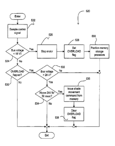
driving the motor 130 via the H-bridge motor drive circuit 132 in accordance
with the new
command at step 824.
[0074] If the reset counter is not equal to zero at step 826, the
microcontroller 134 stores
the present position as the initial position in the memory at step 830. If the
shade movement
command would not send the shade fabric 112 outside the open and closed limits
at step 832, the
motor is driven appropriately at step 824. Otherwise, the desired position is
clipped (i.e.,
adjusted) to be within the open and closed limits at step 834 and the motor is
driven accordingly
at step 824.
[0075] Referring to Fig. 8B, if the shade fabric 112 is presently moving
at step 812 and
the microcontroller 134 has received a new shade movement command (i.e.,
having a different
desired position) at step 836, a determination is made at step 838 as to
whether the shade
movement command originated from the buttons 144 of the electronic drive unit
120. If not, the
microcontroller stores the new command type, the new desired position, and the
initial position
in the memory 138 at step 840. If the new command would cause the shade fabric
112 to move
- 19 -
CA 02684642 2009-10-16
WO 2008/130982 PCT/US2008/060448
outside the open and closed limits at step 842, the microcontroller 134
adjusts the desired
position to be within the open and closed limits at step 844. If the shade
movement command is
from the buttons 144 at step 838, the microcontroller 134 stores the invalid
position as the
desired position at step 846. Finally, the microcontroller 134 appropriately
drives the motor 130
at step 824.
[0076] Fig. 9 is a simplified flowchart of a motor procedure executed
periodically by the
microcontroller 134, for example, approximately every 6 msec. If the shade
fabric 112 is at the
desired position at step 910 or if the shade fabric is not moving, but is
close enough to the
desired position (e.g., within eight Hall effect sensor edges) at step 912,
the microcontroller 134
stops driving the motor 130 at step 914. The microcontroller 134 then clears
the reset counter at
step 916 and stores the invalid position as the desired position in the memory
138 at step 918,
before the procedure 900 exits. If the shade fabric is not at the desired
position at step 910 and
is not close enough to the desired position at step 912, the microcontroller
134 continues to drive
the motor 130 at step 920 and exits the procedure 900.
[0077] While the microcontroller 134 of the first embodiment of the
present invention
controlled the motor 130 to off, the microcontroller could alternatively scale
back driving the
motor rather than simply stopping the motor if the bus voltage VBUS drops
below the first
voltage threshold Vali. For example, the microcontroller 134 could control the
motor 130 such
that the magnitude of the bus voltage VBUS is maintained at a desired overload
magnitude (that is
less than the nominal magnitude, i.e., 30 VDc) during overload conditions.
[0078] Fig. 10 is a simplified flowchart of a bus voltage monitor
procedure 1020
executed periodically (e.g., every 572 [isec) by the microcontroller 134
according to a second
embodiment of the present invention. At step 1022, the microcontroller 134
samples the control
signal BUS MNTR. If the bus voltage VBUS is less than or equal to the first
voltage threshold
VTH1 at step 1024, the controller 134 stores the present duty cycle of the PWM
signal driving the
H-bridge motor drive circuit 132 at step 1025 and sets the OVERLOAD flag at
step 1026. Next,
the controller 134 begins to decrease the duty cycle of the PWM signal driving
the H-bridge
motor drive circuit 132. Specifically, microcontroller 134 calculates the
difference VDIFF
between the actual magnitude of the bus voltage VBUS and a desired overload
magnitude (e.g.,
approximately 20 V) at step 1028, and determines the desired duty cycle DC of
the PWM signal
in response to the difference VDIFF at step 1030, e.g., by using the equation
- 20 -
CA 02684642 2009-10-16
WO 2008/130982 PCT/US2008/060448
DC = a = VDIFF + DCTYP,
(Equation 1)
where DCTyp is the typical duty cycle value of the PWM signal that should
cause the magnitude
of the bus voltage VBUS to be close to the desired overload magnitude. Next,
the microcontroller
134 generates the PWM signal at step 1032 with the duty cycle DC determined at
step 1030, and
the procedure 1020 exits.
[0079] When the bus voltage monitor procedure 1020 is executed again and
the
magnitude of the bus voltage VBUS is greater than the first voltage threshold
VTFH at step 1024, a
determination is made at step 1034 as to whether the OVERLOAD flag is set. If
the
OVERLOAD flag is set at step 1034, but the magnitude of the bus voltage VBUS
is not greater
than the second voltage threshold VTH2 at step 1036, the microcontroller 134
determines the
appropriate duty cycle and drives the PWM signal once again at steps 1028,
1030, 1032. When
the magnitude of the bus voltage VBUS is greater than the second voltage
threshold VTH2 at
step 1036, but has not been greater than the second voltage threshold VTH2 for
a predetermined
amount of time (e.g., 50 msec) at step 1038, the procedure 1020 simply exits.
However, when
the magnitude of the bus voltage VBUS has been greater than the second voltage
threshold VTH2
for the predetermined amount of time at step 1038, the microcontroller 134
drives the PWM
signal with the duty cycle stored in the memory 138 at step 1040, and clears
the OVERLOAD
flag at step 1042, before the procedure 1020 exits.
[0080] Fig. 11 is a simplified flowchart of a bus voltage monitor
procedure 1120
executed periodically (e.g., every 572 [tsec) by the microcontroller 134
according to a third
embodiment of the present invention. The bus voltage monitor procedure 1120 is
identical to
the bus voltage monitor procedure 520 of Fig. 5B, except that the
microcontroller 134 now
decreases the amount of current delivered to the motor by storing the present
duty cycle of the
PWM signal in the memory 138 at step 1125 and then decreasing the duty cycle
of the PWM
signal to a predetermined duty cycle (e.g., 50%) at step 1126 rather than
simply stopping the
motor (i.e., at step 526 of Fig. 5B). Further, the microcontroller 134
increases the duty cycle of
the PWM signal stored in the memory 138 at step 1136.
[0081] Fig. 12A is a simplified schematic diagram of a bus voltage
monitor circuit 1250
according to a fourth embodiment of the present invention. The bus voltage
monitor circuit
1250 provides a discrete-logic control signal BUS MNTR' to the microcontroller
134. The
control signal control signal BUS MNTR' is high (i.e., approximately equal to
the supply
-21 -
CA 02684642 2009-10-16
WO 2008/130982 PCT/US2008/060448
voltage Vcc) when the magnitude of the bus voltage VBUS is at an appropriate
level. When the
magnitude of the bus voltage VBUS falls below a third voltage threshold VTH3,
the control signal
BUS MNTR' is controlled low (i.e., to circuit common or approximately zero
volts).
Accordingly, the microcontroller 134 does not require an analog-to-digital
converter to receive
the control signal BUS MNTR'.
[0082] The bus voltage monitor circuit 1250 comprises a zener diode Z10
coupled in
series with a resistor R12 (e.g., having a resistance of 10 kt2) between the
bus voltage VBUS and
circuit common. For example, the zener diode Z10 has a break-over voltage of
approximately
14 V, such that when the magnitude of the bus voltage VBUS is above the third
voltage threshold
VTH3 (e.g., approximately 15 V), the zener diode Z10 conducts a current
through a resistor R14
(e.g., having a resistance of 10 kg) and into the base of a first NPN
transistor Q16. The first
transistor Q16 is rendered conductive, thus pulling the base of a NPN second
transistor Q20 to
circuit common. Accordingly, the second transistor is rendered non-conductive.
The collector
of the second transistor Q20 provides the control signal BUS MNTR' to the
microcontroller
134. When the second transistor Q20 is non-conductive, the control signal BUS
MNTR' is
pulled high to the supply voltage Vcc through a resistor R22 (e.g., having a
resistance of 2.2
kg). For example, both transistors Q16, Q20 are part number MPSA06
manufactured by On
Semiconductor.
[0083] When the voltage the magnitude of the bus voltage VBUS drops below
the third
voltage threshold VTH3 (i.e., 15 V), the first transistor Q16 is rendered non-
conductive and the
collector is pulled high to the supply voltage Vcc through a resistor R18
(e.g., having a
resistance of 10 kg). The resistor R18 conducts a current through the base of
the second
transistor Q20, thus rendering the second transistor conductive. The control
signal
BUS MNTR' is pulled down to circuit common (i.e., low) when the bus voltage
VBUS is below
the third voltage threshold VTH3. When the voltage the magnitude of the bus
voltage VBUS rises
back above the third voltage threshold VTH3, the control signal BUS MNTR' is
once again
pulled up to the supply voltage Vcc (i.e., high).
[0084] Fig. 12B is a simplified flowchart of a bus voltage monitor
procedure 1220
according to the fourth embodiment of the present invention. The
microcontroller 134 executes
the bus voltage monitor procedure 1220 periodically (e.g., every 572 [tsec)
when receiving the
control signal BUS MNTR' from the bus voltage monitor circuit 1250. The bus
voltage monitor
- 22 -
CA 02684642 2012-11-08
procedure 1220 is identical to the bus voltage monitor procedure 520 of Fig.
5B, except that the
microcontroller 134 determines if the control signal BUS_MNTR' is low or high
at steps 1224
and 1232, respectively. Also, at step 1234, the microcontroller 134 determines
if the control
signal BUS_MNTR` has been high for at least 50 msec.
[0085] The present invention describes a closed loop algorithm for
controlling a
motorized roller shade through a motor overload condition or a low-line
condition. An open
loop algorithm for controlling a motorized roller shade through a motor
overload condition or a
low-line condition is described in greater detail in co-pending, commonly-
assigned U.S. Patent,
7,737,653 entitled METHOD OF
CONTROLLING A MOTORIZED WINDOW TREATMENT.
100861 While the present invention has been described with reference to
motorized roller
shades, the method of the present invention could be applied to any type of
motorized window
treatment that includes a motor drive, such as, for example, motorized
draperies and motorized
Roman shades.
100871 Although the present invention has been described in relation to
particular
embodiments thereof, many other variations and modifications and other uses
will become
apparent to those skilled in the art. It is preferred, therefore, that the
present invention be limited
not by the specific disclosure herein, but only by the appended claims.
-23-