Note: Descriptions are shown in the official language in which they were submitted.
CA 02684705 2009-10-20
WO 2008/150767 PCT/US2008/064867
ACTIVE CONTROLLED BENDING IN MEDICAL DEVICES
CROSS-REFERENCE TO RELATED CASES
[0001] This application claims priority to, and the benefit of Provisional
U.S. Patent
Application Serial No. 60/932,413, filed May 31, 2007, the entirety of which
is incorporated
herein by reference.
TECHNICAL FIELD
[0002] The present invention generally relates to medical devices such as
endoscopes
and catheters. More specifically, the invention relates to flexible medical
devices that are
bendable and steerable in order to negotiate and access various areas within a
patient.
BACKGROUND INFORMATION
[0003] It has become well established that there are major public health
benefits from
early detection and treatment of disease of internal organs such as the
alimentary and
excretory canals and airways, e.g., the colon, esophagus, stomach, urethra,
bladder, ureter,
kidney, lungs, bronchi, uterus, and other organ systems. Early detection of
such diseases can
be accomplished by periodic medical examinations aided by modern medical
procedures and
devices such as an endoscope. A conventional imaging endoscope used for such
procedures
generally comprises a flexible tube with a fiber optic light guide that
directs illuminating light
from an external light source to the distal tip where it illuminates the
region (i.e., tissue,
occlusive objects) to be examined. Frequently, additional optical components
are
incorporated to adjust the spread of the light exiting the fiber bundle and
the distal tip. An
objective lens and fiber optic imaging light guide communicating with a camera
at the
proximal end of the endoscope, or an imaging camera chip at the distal tip,
produce an image
that is displayed to the operator. In addition, most endoscopes include one or
more working
channels through which medical devices such as biopsy forceps, snares,
fulguration probes,
and other tools may be passed.
CA 02684705 2009-10-20
WO 2008/150767 PCT/US2008/064867
-2-
[0004] Some endoscopes and electrophysiology catheters have means for steering
or
deflecting the distal tip of the endoscope to follow the pathway of the
anatomy under
examination such as the colon, bladder, kidney, and heart. Deflection or
articulation is often
a desirable characteristic in these types of medical devices to minimize
friction force and
trauma to the surrounding tissue, and to survey targeted examination sites.
Navigation of the
endoscope through various areas within a patient improves the success of the
examination
and minimizes pain, side effects, risk, or sedation to the patient.
[0005] In order to achieve active deflection at the distal flexible portion of
the
endoscope, control cables or wires are carried within the endoscope shaft
connecting the
distal end to a set of controls in a handle. By manipulating the controls, the
operator is able
to steer the endoscope during insertion and direct it to a region of interest.
[0006] There are many design and performance challenges inherent in these
devices.
Some of these challenges include achieving planar deflection at the tip as
well as preventing
the shaft from buckling or forming a series of "S" shapes from the tension of
pull wire
mechanisms. Other challenges faced by the designers of these devices include
being able to
keep an individual bend in one plane, achieving the appropriate amount of
angular deflection
and achieving multiple directions of deflection.
[0007] Typically, flexible endoscopes are very expensive medical devices.
Because
of the expense, these endoscopes are built to withstand multiple uses upon
many patients and
repeated disinfections. Conventional endoscopes are generally built of strong
composite
material structures such as metals and plastics that do not degrade under
repeated cleaning
and high temperatures. These material structures decrease the flexibility of
the endoscope
and can compromise patient comfort. Furthermore, conventional endoscopes are
complex
and fragile instruments that frequently need expensive repair as a result of
damage during use
or during a disinfection procedure.
[0008] To overcome these and other problems, the development of a low cost
endoscope would allow endoscopes to be used for a single procedure and then
disposed,
eliminating the need for preparation and cleaning and increasing the total
volume of
endoscopes required. This larger volume would enable the manufacturer to
achieve
economies of scale and to incorporate manufacturing methods that are not
economical when
CA 02684705 2009-10-20
WO 2008/150767 PCT/US2008/064867
-3-
used in current volumes and are only economical in large volumes (100,000
units/per year).
The low cost endoscope should be packaged sterile or disinfected and be
capable of being
used for a single procedure without endoscope preparation and then discarded.
The
endoscope should include one or more of the following features: better
navigation and
tracking, a superior interface with the operator, improved access by reduced
frictional forces
upon the lumenal tissue, increased patient comfort, greater clinical
productivity and patient
throughput than is currently available with a conventional endoscope, a lower
risk of cross-
contamination and the ability to be used across more procedures.
SUMMARY OF THE INVENTION
[0009] It thus would be desirable to provide a new device with active
controlled
bending and methods for making flexible shafts for medical devices. It would
be particularly
desirable to provide such a device and method that would achieve planar
deflection at the tip
as well as preventing the shaft (non-deflecting portion) from buckling or
forming a series of
"S" shapes from the tension of pull wire mechanisms in comparison to prior art
devices. It
also would be desirable to provide such a device that would be able to keep an
individual
bend in one plane, achieve the appropriate amount of angular deflection and
achieve multiple
directions of deflection. Such deflection devices would be simple in
construction and less
costly than prior art devices, and such methods would not require highly
skilled users to
utilize the device.
[0010] A particular embodiment of the present invention relates to a flexible
endoscope having a handle and a flexible shaft extending from the handle. The
shaft includes
a distal portion having a tubular wall defining a central lumen and a least
two smaller lumens
extending longitudinally through at least a portion of the tubular wall and a
pull wire is
disposed within each of the smaller lumens. The distal portion further
includes an
articulation layer disposed over the tubular wall and includes a first series
of slots, which
allow controlled bending of the distal portion by movement of one or more of
the pull wires.
[0011 ] In an alternative embodiment of the present invention, the distal
portion
further includes a second series of slots. The second series of slots may be
offset from the
first series of slots, which allows controlled bending of the distal portion
in more than one
CA 02684705 2009-10-20
WO 2008/150767 PCT/US2008/064867
-4-
plane. The spacing between the slots in the first series of slots may be the
same or different
from the spacing between the slots in the second series of slots. Similarly,
the slot width of
the first series of slots may be the same or different from the slot width of
the second series of
slots. By varying the spacing between the slots and/or the slot with, the
bending
characteristics in different planes can be customized. In addition, the
geometric shape of the
slots (e.g., rounded or squared) can be varied to further customize the
bending characteristics
of the distal portion.
[0012] In another aspect of the invention, the endoscope of the present
invention
further includes an outer sleeve disposed on the outside of the flexible shaft
to provide a
smooth exterior surface. A variety of lubrications and/or drug coatings can
also be included
on the outer sleeve to reduce friction or treat portions of the patient being
examined.
[0013] In a further aspect of the invention, the handle of the endoscope
further
includes a control system. The control system may include, for example, knobs,
hubs, or
levers attached to the pull wires to assist in controlled bending of the
distal portion by
movement of the control system.
[0014] In yet another aspect of the invention, the endoscope of the present
invention
further includes radiopaque markers or radiopaque materials when fluoroscopy
is being
utilized to ensure proper positioning of the endoscope.
[0015] In another alternative embodiment of the present invention, the
flexible shaft
section includes a series of stacked rings. Each ring includes at least two
inwardly extending
recesses positioned at predetermined intervals around the outer circumference
of each ring.
A flat pull wire in disposed in each of the recesses, which allow controlled
bending of the
flexible shaft by movement of one or more of the pull wires. The flexible
shaft may also
include an outer sleeve disposed on the outside of the flexible shaft to
provide a smooth
exterior surface. A variety of lubrications and/or drug coatings can also be
included on the
outer sleeve to reduce friction or treat portions of the patient being
examined.
[0016] In yet another alternative embodiment of the present invention, the
flexible
shaft section includes a series of stacked rings and an inner tube is disposed
along the inside
of the series of stacked rings. The inner tube has at least two groves running
longitudinally
along the outer circumference of the inner tube. A flat pull wire in disposed
in each of the
CA 02684705 2009-10-20
WO 2008/150767 PCT/US2008/064867
-5-
grove, which allow controlled bending of the flexible shaft by movement of one
or more of
the pull wires. The flexible shaft may also include an outer sleeve disposed
on the outside of
the flexible shaft to provide a smooth exterior surface. A variety of
lubrications and/or drug
coatings can also be included on the outer sleeve to reduce friction or treat
portions of the
patient being examined.
BRIEF DESCRIPTION OF THE DRAWINGS
[0017] For a fuller understanding of the nature and operation of various
embodiments
according to the present invention, reference is made to the following
description taken in
conjunction with the accompanying drawing figures wherein like reference
characters denote
corresponding parts throughout the several views and wherein:
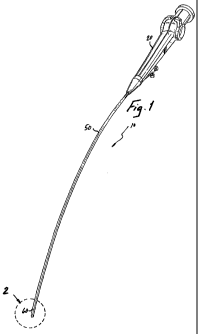
[0018] FIG. 1 depicts a schematic rendering of an endoscope incorporating
features
of the present invention;
[0019] FIG. 2A depicts a schematic rendering of the distal portion of the
endoscope
shown in FIG. 1 with the first active deflection section in a straight
position and the second
active deflection section bent downward;
[0020] FIG. 2B depicts a schematic rendering of the distal portion of the
endoscope
shown in FIG. 1 with the first active deflection section bent downward and the
second active
deflection section in a straight position;
[0021 ] FIG. 2C depicts a schematic rendering of the distal portion of the
endoscope
shown in FIG. 1 with the first active deflection section bent to the left and
the second active
deflection section bent downward;
[0022] FIG. 2D depicts a schematic rendering of the distal portion of the
endoscope
shown in FIG. 1 with the first active deflection section bent to the right and
the second active
deflection section bent upward;
[0023] FIG. 2E depicts a schematic rendering of the distal portion of the
endoscope
shown in FIG. 1 with the first active deflection section bent to the right and
the second active
deflection section bent downward;
CA 02684705 2009-10-20
WO 2008/150767 PCT/US2008/064867
-6-
[0024] FIG. 2F depicts a schematic rendering of the distal portion of the
endoscope
shown in FIG. 1 with the first active deflection section bent to the left and
the second active
deflection section bent upward;
[0025] FIG. 3 depicts an exploded rendering of the handle of the endoscope
shown in
FIG. 1;
[0026] FIG. 4 depicts an enlarged schematic rendering of the assembled right
side
articulation hub shown in FIG. 3;
[0027] FIG. 5 depicts a perspective view of the distal portion of the flexible
shaft
partially cut-away exposing the first and second active deflection sections
according to one
embodiment of the present invention;
[0028] FIG. 6 depicts a partial cut-away side view of the first active
deflection section
of FIG. 5 shown from the perspective indicated by line 6;
[0029] FIG. 7 depicts a partial cut-away top view of the second active
deflection
section of FIG. 5 shown from the perspective indicated by line 7;
[0030] FIG. 8 depicts a cross section of the distal portion of the flexible
shaft of FIG.
taken along the section line 8-8;
[0031 ] FIG. 9 depicts a cross section of the distal portion of the flexible
shaft of FIG.
5 taken along the section line 9-9;
[0032] FIG. 10 depicts a schematic rendering of the distal portion of the
flexible shaft
of FIG. 1 with the second active deflection section bent in a downward
direction;
[0033] FIG. 11 is depicts a schematic rendering of the distal portion of the
flexible
shaft of FIG. 1 with the first active deflection section bent downward and the
second active
deflection section in a straight position;
[0034] FIG. 12 depicts a side view of the distal portion of the flexible shaft
partially
cut-away exposing the first and second active deflection sections according to
a second
embodiment of the present invention;
[0035] FIG. 13 depicts a cross section of the distal portion of the flexible
shaft of
FIG. 12 taken along the section line 13-13;
CA 02684705 2009-10-20
WO 2008/150767 PCT/US2008/064867
-7-
[0036] FIG. 14 depicts a cross section of the distal portion of the flexible
shaft of
FIG. 12 taken along the section line 14-14;
[0037] FIG. 15 depicts a cross section of the distal portion of the flexible
shaft of
FIG. 12 taken along the section line 15-15;
[0038] FIG. 16 depicts a schematic rendering of the distal portion of the
flexible shaft
of FIG. 12;
[0039] FIG. 17 depicts a schematic rendering of the distal portion of the
flexible shaft
of FIG. 12;
[0040] FIG. 18 depicts a side view of the distal portion of the flexible shaft
partially
cut-away exposing the first and second active deflection sections according to
a third
embodiment of the present invention;
[0041 ] FIG. 19 depicts a cross section of the distal portion of the flexible
shaft of
FIG. 18 taken along the section line 19-19;
[0042] FIG. 20 depicts a cross section of the distal portion of the flexible
shaft of
FIG. 18 taken along the section line 20-20;
[0043] FIG. 21 depicts a cross section of the distal portion of the flexible
shaft of
FIG. 18 taken along the section line 21-21;
[0044] FIG. 22 depicts a schematic rendering of the distal portion of the
flexible shaft
of FIG. 18; and
[0045] FIG. 23 depicts a schematic rendering of the distal portion of the
flexible shaft
of FIG. 18.
DESCRIPTION
[0046] As indicated above, the present invention is a flexible endoscope that
allows
an operator to access, and view internal body anatomy of a patient as well as
to insert surgical
instruments into the patient's body. In addition, the endoscope may include
integrated
diagnostic and therapeutic capabilities to allow the operator to treat the
patient in a single
procedure. An endoscope of the present invention can be sufficiently
inexpensive to
CA 02684705 2009-10-20
WO 2008/150767 PCT/US2008/064867
-8-
manufacture such that the endoscope can be considered a single use, disposable
item.
[0047] Referring now to FIG. 1, an endoscope 10 according to one embodiment of
the
present invention includes a handle 20 at the proximal end of the endoscope 10
and a flexible
shaft 50 extending distally from the handle 20. The terms proximal and distal
require a point
of reference. In this application, the point of reference is the perspective
of the user.
Therefore, the term proximal will always refer to an area closest to the user,
whereas distal
will always refer to an area away from the user.
[0048] Referring now also to FIGS. 2A-2F, the flexible shaft 50 has a distal
portion
60 with predictable and planar active deflection capability. This deflection
can be achieved
in multiple directions and at multiple points along the axial orientation. As
shown, the distal
portion 60 is capable of active deflection in two distinct planes. FIGS. 2C-2F
show bending
in a first plane of deflection relative to the handle 20 (up and down) and a
second plane of
deflection (right and left) that is substantially orthogonal to the first
plane of deflection. All
relative descriptions herein such as top, bottom, left, right, up, and down
are with reference to
the figures, and thus should not be construed in a limiting sense.
[0049] Referring now to FIGS. 3 and 4, the handle 20 includes a control system
22 to
control the active deflection capability of the distal portion 60 of the
flexible shaft 50. The
control system 22 comprises two activation hubs 24, 26, and four pull wires
28, 30, 32, 34.
Each activation hub 24, 26 is connected to two of the pull wires and allows
the user to
manipulate the distal portion 60 of the flexible shaft 50 in one plane of
deflection. Additional
activation hubs and/or pull wires could be included in the control system 22
depending on
how many planes of deflection are desired. The pull wires 28, 30, 32, 34 are
made from
stainless steel, polymer filaments, or other metals and alloys such as, for
example, Nitinol.
[0050] The first activation hub 24 is movably attached to the right side of
the handle
20 from the perspective of the user and includes a floating cam 36 and a cam
stop 38. The
proximal ends of pull wires 30 and 34 are connected to the floating cam 36.
When the user
rotates the first activation hub 24 in a clockwise direction as indicated by
line A on FIG. 3,
tension is applied to pull wire 34, and tension is released from pull wire 30,
thereby
deflecting the distal portion 60 of the flexible shaft 50 to the left.
Conversely, when the user
rotates the first activation hub 24 in the opposite, counter-clockwise
direction, tension is
CA 02684705 2009-10-20
WO 2008/150767 PCT/US2008/064867
-9-
applied to pull wire 30 and tension is released from pull wire 34, thereby
deflecting the distal
portion 60 to the right.
[0051 ] The user can achieve up and down deflection of the distal portion 60
of the
flexible shaft 50 by rotating the second activation hub 26 in a similar
manner. The second
activation hub 26 is movably attached to the left side of the handle 20 from
the perspective of
the user and includes a floating cam 40 and a cam stop (not shown). The
proximal ends of
pull wires 28 and 32 are connected to floating cam 40. When the user rotates
the second
activation hub 26 in a clockwise direction as indicated by line B on FIG. 3,
tension is applied
to pull wire 28, and tension is released from pull wire 32, thereby deflecting
the distal portion
60 in an upward direction. Conversely, when the user rotates the second
activation hub 26 in
the opposite, counter-clockwise direction, tension is applied to pull wire 32
and tension is
released from pull wire 28, thereby deflecting the distal portion 60 in a
downward direction.
The control system 22 could comprise additional components or alternative
means for
achieving defection of the distal portion 60 of the flexible shaft 50.
[0052] The handle 20 also includes a working port hub 44. The working port hub
44
provides access to the working channe146 of the endoscope 10. The working
channe146
extends from the working port hub 44 to the distal end 62 of the flexible
shaft 50 and is used
to insert ancillary products such as, for example, guide wires, graspers,
cutters, irrigation,
laser fibers and the like to facilitate a variety of diagnostic and
therapeutic procedures. In
alternative embodiments, the working channe146 may comprise one single central
lumen or
may be further subdivided into a plurality of smaller lumens of various shapes
and sizes to
accommodate different ancillary products.
[0053] The portion of the flexible shaft 50 proximal to the distal portion 60
may
comprise any suitable type of flexible shaft, such as the shaft disclosed in
U.S. patent
application Ser. No. 10/956,011 (U.S. Patent Publication No. 2005-0131279)
which is hereby
incorporated by reference in its entirety. The flexible shaft 50 may be
uniformly flexible or
could comprise a plurality of segments having varying degrees of flexibility
or rigidity. The
flexible shaft 50 includes an outer sleeve 52 disposed on the outside of the
flexible shaft 50 to
provide a smooth exterior surface. The outer sleeve 52 can be made from soft,
thin
polyurethane, LLDPE, silicon, pellethane, polyurethane or other approved
biocompatible
CA 02684705 2009-10-20
WO 2008/150767 PCT/US2008/064867
-10-
materials such as polyethylene, polypropylene or polyvinyl alcohol.
Additionally, the outer
sleeve 52 can be coated with a hydrophilic, lubricious coating such as
HYDROPASSTM
hydrophilic coating available from Boston Scientific Corporation, of Natick,
Mass., and
described in U.S. Pat. Nos. 5,702,754 and 6,048,620, which are herein
incorporated by
reference.
[0054] Referring now to FIGS. 5-9, the distal portion 60 includes a first
active
deflection section 64 and a second active deflection section 66. The first
active deflection
section 64 is capable of deflection in one plane relative to the handle 20 and
the second active
deflection section 66 is capable of deflection in the same plane or a
different plane relative to
the first active deflection section 64. As shown, the two planes are
substantially
perpendicular to each other, however, any degree of offset is acceptable
depending on the
desired application. In alternate embodiments, the first and/or second active
deflection
sections could each be more or less than two way deflectable.
[0055] The distal portion 60 of the flexible shaft 50 comprises an inner shaft
68
(FIGS. 8 and 9). When the first and second active deflection sections 64, 66
are oriented in
the straight position as shown in FIG. 5, the inner shaft 68 defines a
longitudinal axis 70.
The inner shaft 68 includes a central lumen know as the working channe146 and
a plurality
of smaller lumens 72, 74, 76, 78 extending longitudinally through the tubular
wall of the
inner shaft 68. As noted above, the proximal ends of pull wires 28, 30, 32, 34
are connected
to activation hubs 24, 26 in the control system 22. The pull wires 28, 30, 32,
34 extend
distally from the control system 22 and are each disposed in one of the
smaller lumens 72, 74,
76, 78. The working channe146 may have one or more lumens extending from the
working
port hub 44 to the distal end 62 and is used to insert ancillary products such
as, for example,
guide wires, graspers, cutters, irrigation, laser fibers and the like to
facilitate a variety of
diagnostic and therapeutic procedures. Illumination can also be achieved using
fibers or
electrical connection to an imaging sensor at the distal end 62. The inner
shaft 68 is made
from a biocompatible material acceptable for medical use with a low
coefficient of friction
such as polytetrafluoroethylene (PTFE) or polyethylene (PE). Other materials
also may be
appropriate.
[0056] In order to facilitate active deflection (i.e., steering) of the distal
end 62, the
CA 02684705 2009-10-20
WO 2008/150767 PCT/US2008/064867
-11-
distal portion 60 of the flexible shaft 50 includes an articulation layer 80
disposed over the
inner shaft 68. The articulation layer has a first series of slots 82 in the
articulation layer 80
located on opposing sides of the flexible shaft 50. The radial location of the
slots 82 in the
articulation layer 80 determine the direction of bending of the first active
deflection section
64. In the embodiment shown in FIG. 5, the radial location of the slots 82
will allow the user
to manipulate the first active deflection section 64 to the right and left.
[0057] The articulation layer 80 can be formed by various methods including
extruding a cylinder with a central lumen in place and then cutting the
cylinder tube with a
knife, laser, milling tool, water jet, or other material removal mechanism to
form the slots 82.
Alternatively, the articulation layer 80 can be molded with the slots 82 in
place. As will be
appreciated, the shape, size, geometry (e.g., rounded or squared), and angle
of the slots 82
may be uniform or may vary along the length of the articulation layer 80.
Similarly, the
distance between adjacent slots 82 may be uniform or may vary in order to
tailor the bending
and torque fidelity characteristics of the distal portion 60 of the flexible
shaft 50. As with the
inner shaft 68 discussed above, the articulation layer 80 should be made of a
biocompatible
material accepted for medical use that will bend but will not collapse.
Suitable materials
include polyurethane, polyethylene, polypropylene, or other biocompatible
polymers. Other
materials and/or fabrication techniques are possible.
[0058] In order to accomplish active deflection of the first active deflection
section
64, pull wires 30, 34 disposed in smaller lumens 74, 78 respectively, extend
from the first
activation hub 24 along the length of the flexible shaft 50 and terminate at a
location distal to
the first active deflection section 64. As discussed above, when the user
rotates the first
activation hub 24 in a clockwise direction, tension is applied to pull wire
34, and tension is
released from pull wire 30, thereby deflecting the first active deflection
section 64 to the left.
Conversely, when the user rotates the first activation hub 24 in the opposite,
counter-
clockwise direction, tension is applied to pull wire 30 and tension is
released from pull wire
34, thereby deflecting the first active deflection section 64 to the right.
[0059] In order to facilitate additional active deflection (i.e., steering) of
the distal
portion 60 of the flexible shaft 50, the articulation layer 80 has a second
series of slots 84 on
opposing sides of the flexible shaft 50. To achieve bending in a second plane,
the second
CA 02684705 2009-10-20
WO 2008/150767 PCT/US2008/064867
-12-
series of slots 84 can be rotated relative to the first series of slots 82. In
the embodiment
shown in FIG. 5, the second series of slots 84 is rotated about 90 degrees
relative to the first
series of slots 82. In this orientation, the two planes of deflection will be
substantially
perpendicular to each other, therefore, the user will be able to manipulate
the second active
deflection section 66 in an upward and downward direction.
[0060] In order to accomplish active deflection of the second active
deflection section
66, pull wires 28, 32 disposed in smaller lumens 72, 76 respectively, extend
from the second
activation hub 26 along the length of the flexible shaft 50 and terminate at a
location distal to
the second active deflection section 66, but proximal to the first active
deflection section 64
(i.e., between the two active deflection sections). As discussed above, when
the user rotates
the second activation hub 26 in a clockwise direction, tension is applied to
pull wire 28, and
tension is released from pull wire 32, thereby deflecting the second active
deflection section
66 in an upward direction. Conversely, when the user rotates the second
activation hub 26 in
the opposite, counter-clockwise direction, tension is applied to pull wire 32
and tension is
released from pull wire 28, thereby deflecting the second active deflection
section 66 in a
downward direction.
[0061 ] Referring now to FIG. 10, the second active deflection section 66 is
shown
bent in a downward direction and the first active deflection section 64 is in
a straight
position. To achieve this orientation, the user would rotate the second
activation hub 26 in a
counter-clockwise direction, thus applying tension to pull wire 32. The outer
sleeve 52 is
shown cut away in the region of the second active deflection section 66
showing that one side
of the second series of slots 84 has been compressed by the tension applied to
pull wire 32
and the opposing side of the second series of slots 84 has been expanded by
the release of
tension on pull wire 28. This type of bend is sometimes referred to as an
"elbow" bend
because of its location along the length of the flexible shaft 50.
[0062] Referring now to FIG. 11, the first active deflection section 64 is
shown bent
to the left and the second active deflection section 66 is in a straight
position. To achieve this
orientation, the user would rotate the first activation hub 24 in a clockwise
direction, thus
applying tension to pull wire 34. The outer sleeve 52 is shown cut away in the
region of the
first active deflection section 64 showing that one side of the first series
of slots 82 has been
CA 02684705 2009-10-20
WO 2008/150767 PCT/US2008/064867
- 13-
compressed by the tension applied to pull wire 34 and the opposing side of the
first series of
slots 82 has been expanded by the release of tension on pull wire 32. This
type of bend is
sometimes referred to as an "wrist" bend because of its location along the
length of the
flexible shaft 50.
[0063] Prior to use, the tension of the pull wires 28, 30, 32, 34 is typically
adjusted
such that the first and second active deflection sections 64, 66 are both in
substantially
straight orientations relative to each other. This type of configuration is
used to insert the
distal end 62 of the endoscope 10 into the interior anatomy of a patient.
[0064] To ensure proper positioning, it is desirable for the endoscope 10 to
be visible
using fluoroscopy, echocardiography, intravascular ultrasound, angioscopy, or
another means
of visualization. Where fluoroscopy is utilized, any or all of the endoscope
10 may be
produced with a material that is compounded with a radiopaque filler, or a
radiopaque marker
may be included on any portion of the device that would be useful to
visualize. Examples of
a radiopaque fillers that can be used are barium sulfate and bismuth
subcarbonate.
Radiopaque markers can be made from any of a number of materials including,
for example,
gold, platinum, or tungsten.
[0065] Referring now back to FIGS. 2A-2F, movements of the first and second
active
deflection sections 54, 56 will be described in greater detail. FIG. 2A shows
the second
active deflection section 66 bent in a downward direction and the first active
deflection
section 64 is in a straight position. FIG. 2B shows the first active
deflection section 64 bent
to the left and the second active deflection section 66 in a straight
position.
[0066] FIGS. 2C-2F show more complex bending of the distal portion 60 in
multiple
planes of deflection. FIG. 2C shows the first active deflection section 64
bent to the left and
the second active deflection section 66 bent downward. To achieve this
orientation, the user
would rotate the first activation hub 24 in a clockwise direction, thus
applying tension to pull
wire 34 and deflection the first active deflection section 64 to the left. The
user would also
rotate the second activation hub 26 in a counter-clockwise direction, thus
applying tension to
pull wire 32 and bending the second active deflection section 66 downward.
[0067] FIG. 2D shows the first active deflection section 64 bent to the right
and the
second active deflection section 66 bent upward. To achieve this orientation,
the user would
CA 02684705 2009-10-20
WO 2008/150767 PCT/US2008/064867
-14-
rotate the first activation hub 24 in a counter-clockwise direction, thus
applying tension to
pull wire 30 and bending the first active deflection section 64 to the right.
The user would
also rotate the second activation hub 26 in a clockwise direction, thus
applying tension to pull
wire 28 and bending the second active deflection section 66 upward.
[0068] FIG. 2E shows the first active deflection section 64 still bent to the
right while
the second active deflection section 66 is now bent downward. To achieve this
orientation,
the user would keep the first activation hub 24 rotated in a counter-clockwise
direction as it
was in reference to FIG. 2D, but the user would rotate the second activation
hub 26 in a
counter-clockwise direction. This counter-clockwise rotation would release the
tension on
pull wire 28 and apply tension to pull wire 32, thereby bending the second
active deflection
section 66 in a downward direction.
[0069] FIG. 2F shows the first active deflection section 64 bent to the left
and the
second active deflection section 66 bent upward. To achieve this orientation,
the user would
rotate the first activation hub 24 in a clockwise direction, thus applying
tension to pull wire
34 and bending the first active deflection section 64 to the left. The user
would also rotate
the second activation hub 26 in a clockwise direction, thus applying tension
to pull wire 28
and bending the second active deflection section 66 in an upward direction. As
noted above,
additional orientations and amount of bending of the first and second
deflection sections 64,
66 are possible depending on the several variables including, for example, the
amount of
tension applied to the pull wires, the distance or spacing between the slots,
axial location of
the slots in the articulation layer 80, as well as the depth, width and shape
of the slots.
Furthermore, additional planes and/or locations or deflection along the length
of the flexible
shaft 50 can be achieved by increasing the number of pull wires and deflection
sections.
[0070] FIGS. 12-17 shows an alternative embodiment of a distal portion 160 of
a
flexible shaft 50 for use with an endoscope of the present invention. The
distal portion 160 is
performs the same function as the distal portion 60 described above, and
therefore like
reference numerals preceded by the numeral "1" are used to indicate like
elements. In this
embodiment, the distal portion 160 is made of series of stacked rings, such as
the articulation
joints disclosed in U.S. patent application Ser. No. 10/956,011 (U.S. Patent
Publication No.
2005-0131279), which is hereby incorporated by reference in its entirety.
CA 02684705 2009-10-20
WO 2008/150767 PCT/US2008/064867
-15-
[0071 ] In this embodiment, the distal portion 160 comprises a plurality of
thin rigid
rings 186a, 186b, 186c, etc., concentrically aligned defining an inner lumen
188. Each ring
may be deep drawn, rolled and welded, or otherwise formed of stainless-steel
or other
biocompatible material that allows the ring to be rigid while having a thin
wall profile in
order to maximize the size of the inner lumen 188.
[0072] Each ring is connected to an adjacent ring with a pair of springs 190
laterally
disposed on opposite sides of the inside wall of the rings. The springs 190
are welded,
brazed, adhesively secured or otherwise bonded to an inner circumference of
each ring
segment joining adjacent rings together. The springs are secured at a
predetermined radial
location substantially aligned with the smaller lumens 172, 174, 176, 178 of
the flexible
shaft. For example, if three rings 186a, 186b, and 186c are aligned, the rings
186a and 186b
are joined together with springs located at the 0 degree and 180 degree radial
location on the
rings, while ring 186b is joined to ring 186c with orthogonally aligned
springs located at the
90 degree and 270 degree radial location on the rings. The springs are made of
stainless steel
or other biocompatible metal and springs of varying stiffness may be used
along the length of
the distal portion 160 to control the radius of curvature along the length of
the distal portion.
[0073] A space is formed between adjacent rings so that the pair of springs
190 forms
a flexible joint that can bend in directions that are away from the
longitudinal axis 170 of the
shaft 150 but has limited ability to compress the shaft 150 in the direction
of the longitudinal
axis 170 of the shaft 150.
[0074] As shown in FIG. 12, when viewed from the side, each ring is not
completely
cylindrical but includes a front surface 194 and rear surface 196. Referring
now also to
FIGS. 16-17, the front 194 and rear 196 surfaces are sloped away from the
point adjacent
rings are joined by the springs, thereby forming a V-shaped gap 192 in which
the distal
portion 160 can bend. The sloped faces of the rings allow increased movement
between
adjacent rings and also provide a stop to prevent adjacent rings from sliding
past each other.
[0075] Each spring 190 defines a small lumen with pull wires 128, 130, 132,
134
disposed therein. The distal portion of each pull wire is connected to the
distal portion 160 of
the flexible shaft section 150. As discussed above, in this embodiment, the
two sets of pull
wires (28, 32 and 30, 34) are rotated by 90 degrees allowing for two degrees
of freedom (or
CA 02684705 2009-10-20
WO 2008/150767 PCT/US2008/064867
-16-
deflection directions). In alternative embodiments, additional sets of pull
wires and springs
190 may be included to allow for additional degrees of freedom.
[0076] A flexible outer sleeve 152 is disposed on the outside of the rings
186a, 186b,
186c, etc., to provide a smooth exterior surface. The outer sleeve 152 can be
made from soft,
thin polyurethane, LLDPE, silicon, pellethane, polyurethane or other approved
biocompatible
materials such as polyethylene, polypropylene or polyvinyl alcohol.
Additionally, the outer
sleeve 152 can be coated with a hydrophilic, lubricious coating such as
HYDROPASSTM
hydrophilic coating available from Boston Scientific Corporation, of Natick,
Mass., and
described in U.S. Pat. Nos. 5,702,754 and 6,048,620, which are herein
incorporated by
reference.
[0077] The flexible shaft 150 may further comprise an inner tube 198 running
along
the inside of the inner shaft 168 and the inner lumen 188. The inner tube has
one or more
lumens extending from the working port hub 144 to the distal end 162 and is
used to insert
ancillary products such as, for example, guide wires, graspers, cutters,
irrigation, laser fibers
and the like to facilitate a variety of diagnostic and therapeutic procedures.
The inner tube
198 is made from a biocompatible material acceptable for medical use with a
low coefficient
of friction such as polytetrafluoroethylene (PTFE) or polyethylene (PE). Other
materials also
may be appropriate.
[0078] Active deflection of the distal portion 160 is accomplished in a
similar manner
as for distal portion 60 described above. Multiple active deflection sections
(i.e., areas along
the axis 170 where the distal portion 160 can bend in different planes or with
different radius
of curvature) can be achieved by the use of springs of varying tensions and by
terminating the
pull wires 128, 130, 132, 134 at different locations along the axis. For
example, when pull
wires 130, 134 disposed in smaller lumens 174, 178 respectively, extend from
the first
activation hub 124 along the length of the flexible shaft 150 and terminate at
a location near
the distal end 162 of the distal portion 160, a first active deflection
section 164 is created.
When pull wires 128, 132 disposed in smaller lumens 172, 176 respectively,
extend from the
second activation hub 126 along the length of the flexible shaft 150 and
terminate at a
location proximal to the first active deflection section 164, a second active
deflection section
166 is created. As shown, these two active deflection sections 164, 166 are
substantially
CA 02684705 2009-10-20
WO 2008/150767 PCT/US2008/064867
-17-
perpendicular to each other and operate in the same manner as active
deflection sections 64,
66 described above.
[0079] For smaller versions of a flexible shaft 150, the cross-section area
occupied by
the springs 190 and round pull wires 128, 130, 132, 134 may be prohibitive to
other
functional requirements of the device such as working channel, optics, etc. In
these
instances, an alternative embodiment that utilizes flat pull wires would be
advantageous.
FIGS. 18-23 shows an alternative embodiment of a distal portion 260 of a
flexible shaft 150
for use with an endoscope 10 of the present invention. The distal portion 260
is performs the
same function as the distal portion 160 described above, and therefore like
reference
numerals preceded by the numeral "2" are used to indicate like elements.
[0080] In this embodiment, the distal portion 260 is made of series of stacked
rings
286a, 286b, 286c, etc. concentrically aligned defining an inner lumen 288.
Each ring may be
deep drawn, rolled and welded, or otherwise formed of stainless-steel or other
biocompatible
material that allows the ring to be rigid while having a thin wall profile in
order to maximize
the size of the inner lumen 288. Inwardly extending recesses 273 are
positioned at
predetermined intervals around the outer circumference of each of the rings
286 to receive
flat pull wires 228, 230, 232, 234.
[0081 ] A flexible outer sleeve 252 is disposed on the outside of the rings
286a, 286b,
286c, etc., to provide a smooth exterior surface. The outer sleeve 252 can be
made from soft,
thin polyurethane, LLDPE, silicon, pellethane, polyurethane or other approved
biocompatible
materials such as polyethylene, polypropylene or polyvinyl alcohol.
Additionally, the outer
sleeve 252 can be coated with a hydrophilic, lubricious coating such as
HYDROPASSTM
hydrophilic coating available from Boston Scientific Corporation, of Natick,
Mass., and
described in U.S. Pat. Nos. 5,702,754 and 6,048,620, which are herein
incorporated by
reference.
[0082] In alternative embodiments, these flat pull wires 228, 230, 232, 234
could run
completely along the inside of the rings or could weave from inside one ring
to the outside of
the next. In the embodiment where the flat pull wires 228, 230, 232, 234 run
along the inside
of the rings, the flexible shaft 250 may further comprise an inner tube 298
running along the
inside of the rings 286a, 286b, 286c with groves to guide the location of the
flat pull wires
CA 02684705 2009-10-20
WO 2008/150767 PCT/US2008/064867
-18-
228, 230, 232, 234. The inner tube 298 also has one or more lumens extending
from the
working port hub to the distal end 262 and is used to insert ancillary
products such as, for
example, guide wires, graspers, cutters, irrigation, laser fibers and the like
to facilitate a
variety of diagnostic and therapeutic procedures. The inner tube 298 is made
from a
biocompatible material acceptable for medical use with a low coefficient of
friction such as
polytetrafluoroethylene (PTFE) or polyethylene (PE). Other materials may be
appropriate.
[0083] Active deflection of the distal portion 260 is accomplished in a
similar manner
as for distal portion 160 described above. Multiple active deflection sections
(i.e., areas
along the axis 270 where the distal portion 260 can bend in different planes
or with different
radius of curvature) can be achieved by the use of springs of varying tensions
and by
terminating the pull wires 228, 230, 232, 234 at different locations along the
axis.
[0084] The disclosed embodiments are exemplary. The invention is not limited
by or
only to the disclosed exemplary embodiments. Also, various changes to and
combinations of
the disclosed exemplary embodiments are possible and within this disclosure.