Note: Descriptions are shown in the official language in which they were submitted.
CA 02684759 2014-10-08
SURGICALLY IMPLANTABI F KNEE PROSTHESIS WITH CAPTURED KEEL
BACKGROUND OF THE INVENTION
1. Field of the Invention
This invention relates to a prosthesis which is surgically implantable
into a body joint, such as the knee.
2. Background Art
Current knee arthroplasties typically involve replacement of the
arthritic joint surfaces and are known for their use of metal and plastic
components.
They are usually embedded in a polymethylmethacrylate (PMIVLA) cement mantle
to
adhesively and mechanically bond the components to the area of bone exposed
during
the course of surgery.
Typically, this area of exposed bone is 2-3 mm below the area of
existing eroded bone surface and generally requires removal of the entire
subchondral
bone in the area of implant location. In all cases, the subchondral (SC) bone
of the
tibial plateau, which is attached to the remaining articular surface, is
removed as
standard practice for both the total knee (TKR) and partial or
unicompartmental knee
(UKR) replacement procedures.
Further, FDA guidelines generally dictate that when polyethylene (PE)
is used as a bearing surface, whether in conjunction with a metal support
plate or not,
at least 6 mm of PE thickness must be used to prevent fracturing of the PE
during use.
-1-
CA 02684759 2009-11-12
WO 2008/144393 PCT/US2008/063712
When the PE is used on the tibial side of these implant designs, this
requirement leads
to bone resections of the tibial plateau generally greater than 7 mm. The
subchondral
bone thickness on a typical tibial plateau is generally 2-3 mm. Thus, a
typical TKR
or UKR implant will require resection of the entire SC bone present on the
tibial
plateau, leaving only cancellous bone.
The PE is typically held in place by an interference fit or by melt
infusion to a metal backing plate known as the tibial baseplate. This
baseplate, in
turn, is held in place on the now exposed cancellous bone of the tibia by
screws, keels,
posts, or combinations of some or all of these devices. The screws and keels
generally
provide immediate fixation, but these are usually enhanced by the addition of
the
PMMA cement. In the case of perforated keels, tapered and hourglass shaped
posts,
when these projections are set in uncured cement, the cement forms around and
through them and, once hardened, provides an almost indestructible bond
between the
PMMA cement and the tibial baseplate. The cement also permeates the open
cellular
structure of the cancellous bone, thus resulting in the same type of bond
between the
bone and the tibial baseplate. In some unique cases, the metal tibial
baseplate is not
used and an all-PE design is bonded directly to the cancellous bone with the
PMMA
cement utilizing a roughened PE surface or molded posts to facilitate the bond
with
the PMMA cement.
A new generation of tibial hemiarthroplasty (HA) implant designs has
been introduced which do not require significant resection of the SC bone of
the tibial
plateau to function properly. Examples of this are the U.S. Patent Nos.
6,206,927;
6,558,421; 6,966,928; 6,866,684; and 7,341,602, each of which is incorporated
by
reference herein. These THA designs maintain their proper location in the
joint by
interference with preexisting or prepared anatomical shapes present in the
knee joint,
and none require PMMA-cemented protrusions or screws for proper function.
Previous keel designs, whether utilized for T'HA, UKR, or TKR
implants, typically utilize an anteriorly-oriented keel. For example, the
Zimmer
Sbarbaro "skate" implant has a keel aligned in the anterior-posterior (AP)
direction,
with the posterior portion being rounded and sharpened and the anterior
portion
-2-
CA 02684759 2009-11-12
WO 2008/144393
PCULTS2008/063712
having an anterior (forward) pointing distal tip. In order to insert this
particular
shaped keel into a tibia with a cut to accept the keel, the length of the saw
cut needed
to insert the bottommost portion of the keel would be significantly longer the
length
of the keel at the base of the implant, thus allowing the implant to be able
to slide in
an anterior fashion upon implantation in an anterior to posterior insertion
direction.
Other previous keel designs, such as the DePuy "Preservation" UICR,
utilize a keel which extends the majority of the length of the baseplate. In
this
implant, the keel also comprises an hourglass shape in medial-lateral (ML)
section.
Due to the length of the keel and the hourglass design along its length, this
implant
cannot be inserted into the tibia without first making a substantial femoral
cut to
provide access to the tibia, or otherwise inserting the implant via a
lengthwise
insertion from the most anterior portion of the tibial plateau. In other
words, the tibial
plateau, rather than receiving a simple angle saw cut in order to receive the
implant,
must have a milled hourglass shape cut in the plateau which extends through
the most
anterior cortical bone in order for the keel to be inserted into the joint. If
such a milled
cut is not prepared, then a cut equal to the largest width of the keel must be
made,
which would not provide positive locking with the keel unless a mantle of
cement is
used.
BRIEF DESCRIPTION OF l'HE DRAWINGS
FIGURE 1 is a side elevational view of a prosthesis according to the
present invention including a keel with angled anterior and posterior ends;
FIGURE 2 is a bottom perspective view of the prosthesis of FIG. 1;
FIGURE 3 is a side elevational view of a prosthesis according to the
present invention including a keel with a rounded anterior end and angled
posterior
end;
FIGURE 4 is a bottom perspective view of the prosthesis of FIG. 3;
-3-
CA 02684759 2009-11-12
WO 2008/144393 PCT/US2008/063712
FIGURE 5 is a bottom perspective view of a prosthesis according to
the present invention including a keel with rounded anterior and posterior
ends;
FIGURE 6 is a bottom perspective view of a prosthesis according to
the present invention including a keel with rounded anterior and posterior
ends;
FIGURE 7 is a side elevational view of a prosthesis according to the
present invention including a keel with rounded anterior and posterior ends
shown
with reference to a cross-section of the tibia, wherein a representative
thickness
subchondral and cortical bone are represented;
FIGURE 8 is a side elevational view of a prosthesis according to the
present invention including a keel with an angled posterior end and chamfered
anterior
end;
FIGURE 9 is a bottom perspective view of the prosthesis of FIG. 8;
FIGURE 10 is a side elevational view of the prosthesis of FIG. 8 shown
with reference to a cross-section of a tibia, wherein a representative
thickness
subchondral and cortical bone are represented;
FIGURE 11 is a side elevational view of a prosthesis according to the
present invention including a keel with an angled posterior end and oppositely
angled
anterior end;
FIGURE 12 is a bottom perspective view of the prosthesis of FIG. 11;
FIGURE 13 is a side elevational view of the prosthesis of FIG. 11
shown with reference to a cross-section of a tibia, wherein a representative
thickness
subchondral and cortical bone are represented;
FIGURE 14 is a side elevational view of a prosthesis according to the
present invention including a keel with an angled posterior end and a step-
shaped
-4-
CA 02684759 2009-11-12
WO 2008/144393
PCT/US2008/063712
anterior end;
FIGURE 15 is a bottom perspective view of the prosthesis of FIG. 14;
FIGURE 16 is a side elevational view of the prosthesis of FIG. 14
shown with reference to a cross-section of a tibia, wherein a representative
thickness
subchondral and cortical bone are represented;
FIGURE 17 is a side elevational view of a prosthesis according to the
present invention including a keel with a step-shaped posterior end and a
rounded
anterior end;
FIGURE 18 is a bottom perspective view of the prosthesis of FIG. 17;
FIGURE 19 is a side elevational view of the prosthesis of FIG. 17
shown with reference to a cross-section of a tibia wherein a representative
thickness
subchondral and cortical bone are represented;
FIGURE 20 is a side elevational view of a prosthesis according to the
present invention including a keel with a step-shaped posterior end and a
curved
anterior end;
FIGURE 21 is a bottom perspective view of the prosthesis of FIG. 20;
FIGURE 22 is a side elevational view of the prosthesis of FIG. 20
shown with reference to a cross-section of a tibia, wherein a representative
thickness
subchondral and cortical bone are represented;
FIGURE 23 is a side elevational view of a prosthesis according to the
present invention including a keel with a step-shaped posterior end and a
chamfered
anterior end;
FIGURE 24 is a bottom perspective view of the prosthesis of FIG. 23;
-5-
CA 02684759 2009-11-12
WO 2008/144393 PCT/US2008/063712
FIGURE 25 is a side elevational view of the prosthesis of FIG. 23
shown with reference to a cross-section of a tibia, wherein a representative
thickness
subchondral and cortical bone are represented;
FIGURE 26 is a side elevational view of a prosthesis according to the
present invention showing generic keel dimensions;
FIGURE 27 is a bottom plan view of a prosthesis according to the
present invention showing generic keel dimensions;
FIGURE 28 is a side elevational view of a prosthesis according to the
present invention showing exemplary keel dimensions;
FIGURE 29 is a bottom plan view of a prosthesis according to the
present invention showing exemplary keel -dimensions;
FIGURE 30 is a side elevational view of a prosthesis according to the
present invention including a keel with a hooked posterior end and a
relatively longer,
angled anterior end;
FIGURE 31 is a bottom plan view of the prosthesis of FIG. 30;
FIGURE 32 is a front elevational view of the prosthesis of FIG. 30;
FIGURE 33 is a rear perspective view of the prosthesis of FIG. 30;
FIGURE 34 is a side elevational view of the prosthesis of FIG. 30
shown with reference to a cross-section of a tibia, wherein a representative
thickness
subchondral and cortical bone are represented;
FIGURE 35 is a top perspective view of a tibial cut which may be
utilized for receiving the prosthesis of FIG. 30;
-6-
CA 02684759 2009-11-12
WO 2008/144393
PCT/US2008/063712
FIGURE 36 is a side elevational view of a prosthesis according to the
present invention including a keel with an angled posterior end and a
relatively longer,
rounded anterior end;
FIGURE 37 is a bottom perspective view of the prosthesis of FIG. 36;
FIGURE 38 is a side elevational view of the prosthesis of FIG. 36
shown with reference to a cross-section of a tibia, wherein a representative
thickness
subchondral and cortical bone are represented;
FIGURE 39 is a side elevational view of a prosthesis according to the
present invention including a keel with an angled posterior end and a
relatively
shorter, rounded anterior end;
FIGURE 40 is a bottom perspective view of the prosthesis of FIG. 39;
FIGURE 41 is a side elevational view of the prosthesis of FIG. 39
shown with reference to a cross-section of a tibia, wherein a representative
thickness
subchondral and cortical bone are represented;
FIGURE 42 is a side elevational view of a prosthesis according to the
present invention including a keel with an angled posterior end and a
relatively
shorter, rounded anterior end, the prosthesis including a cushioning component
on a
tibial face thereof;
FIGURE 43 is a bottom perspective view of the prosthesis of FIG. 42;
FIGURE 44 is a side elevational view of the prosthesis of FIG. 42
shown with reference to a cross-section of a tibia, wherein a representative
thickness
subchondral and cortical bone are represented;
FIGURE 45 is a side elevational view of a prosthesis according to the
present invention including a keel with an angled posterior end and a
relatively
-7-
CA 02684759 2009-11-12
WO 2008/144393 PCT/US2008/063712
shorter, rounded anterior end, the prosthesis including a cushioning component
on a
femoral face thereof;
FIGURE 46 is a bottom perspective view of the prosthesis of FIG. 45;
FIGURE 47 is a side elevational view of the prosthesis of FIG. 45
shown with reference to a cross-section of a tibia, wherein a representative
thickness
subchondral and cortical bone are represented;
FIGURE 48 is a bottom perspective view of a cushioning component
according to the present invention;
FIGURE 49 is a top perspective view of a femoral face of the
prosthesis of FIG. 45 which is prepared to receive a cushioning component
thereon;
FIGURE 50 is a side elevational view of a prosthesis according to the
present invention which may be utilized for a lateral compartment
implantation, the
prosthesis including a keel having an angled posterior end and a relatively
longer,
angled anterior end;
FIGURE 51 is a bottom perspective view of the prosthesis of FIG. 50;
FIGURE 52 is a top perspective view of the prosthesis of FIG. 50;
FIGURE 53 is a front elevational view of the prosthesis of FIG. 50;
FIGURE 54 is a rear elevational view of the prosthesis of FIG. 50;
FIGURE 55 is a side elevational view of the prosthesis of FIG. 50
shown with reference to a cross-section of a tibia, wherein a representative
thickness
subchondral and cortical bone are represented;
FIGURE 56 is a side elevational view of a prosthesis according to the
-8-
CA 02684759 2009-11-12
WO 2008/144393 PCT/US2008/063712
present invention including a keel with an angled posterior edge, a rounded
anterior
edge, and an angled cross-keel member;
FIGURE 57 is a bottom perspective view of the prosthesis of FIG. 56;
FIGURE 58 is a side elevational view of the prosthesis of FIG. 56
shown with reference to a cross-section of a tibia, wherein a representative
thickness
subchonciral and cortical bone are represented;
FIGURE 59 is a side elevational view of a prosthesis according to the
present invention including a keel with an angled posterior end, a rounded
anterior
end, and an angled cross-keel member extending the depth of the keel;
FIGURE 60 is a bottom perspective view of the prosthesis of FIG. 59;
FIGURE 61 is a side elevational view of a prosthesis according to the
present invention including a keel with an angled posterior end, a rounded
anterior
end, and a cross-keel member extending along the depth of the keel;
FIGURE 62 is a bottom perspective view of the prosthesis of FIG. 61;
FIGURE 63 is a side elevational view of a prosthesis according to the
present invention including a keel with an angled posterior end, an angled
anterior
end, and an angled cross-keel member extending along the depth of the keel at
the
anterior end;
FIGURE 64 is a bottom perspective view of the prosthesis of FIG. 63;
FIGURE 65 is a side elevational view of a prosthesis according to the
present invention including a keel with an angled posterior end, an anterior
end
generally orthogonal to a bottom face of the prosthesis, and a cross-keel
member
extending along the depth of the keel at the anterior end;
-9-
CA 02684759 2009-11-12
WO 2008/144393
PCT/1JS2008/063712
FIGURE 66 is a bottom perspective view of the prosthesis of FIG. 65;
FIGURE 67 is a side elevational view of a prosthesis according to the
present invention including a keel with an angled posterior end, a rounded,
angled
anterior end, and a plurality of angled barb members oriented toward the
anterior end;
FIGURE 68 is a bottom perspective view of the prosthesis of FIG. 67;
FIGURE 69 is a bottom plan view of the prosthesis of FIG. 67;
FIGURE 70 is a side elevational view of the prosthesis of FIG. 67
shown with reference to a cross-section of a tibia, wherein a representative
thickness
subchondral and cortical bone are represented;
FIGURE 71 is a side elevational view of a prosthesis according to the
present invention including a keel with a hooked posterior end, a rounded,
angled
anterior end, and an angled barb member oriented toward the anterior end;
FIGURE 72 is a bottom perspective view of the prosthesis of FIG. 71;
FIGURE 73 is a side elevational view of a prosthesis according to the
present invention including a keel with a hooked posterior end, a rounded,
angled
anterior end, and an angled barb member oriented toward the anterior end,
wherein the
keel tapers at a distal end thereof;
FIGURE 74 is a bottom perspective view of the prosthesis of FIG. 73;
FIGURE 75 is a rear elevational view of the prosthesis of FIG. 73;
FIGURE 76 is a bottom plan view of the prosthesis of FIG. 73;
FIGURE 77 is a side elevational view of the prosthesis of FIG. 73
shown with reference to a cross-section of a tibia, wherein a representative
thickness
-10-
CA 02684759 2009-11-12
WO 2008/144393 PCT/US2008/063712
subchondral and cortical bone are represented;
FIGURE 78 is a bottom perspective view of a prosthesis according to
the present invention including a posterior tab, wherein the keel is omitted
for clarity;
FIGURE 79 is a top perspective view of the prosthesis of FIG. 78;
FIGURE 80 is a side elevational view of the prosthesis of FIG. 78
including a keel similar to FIG. 73 and shown with reference to a cross-
section of a
tibia, wherein a representative thickness subchondral and cortical bone are
represented;
FIGURE 81 is a side elevational view of a prosthesis according to the
present invention including a keel with an expandable portion in the medial-
lateral
direction, wherein the prosthesis is shown with reference to a cross-section
of a tibia,
wherein a representative thickness subchondral and cortical bone are
represented;
FIGURE 82 is a bottom perspective view of the prosthesis of FIG. 81;
FIGURE 83 is a bottom perspective view of the prosthesis of FIG. 81
with the expandable portion actuated;
FIGURE 84 is a rear elevational view of the prosthesis of FIG. 83;
FIGURE 85 is a side elevational view of a prosthesis according to the
present invention including a keel and a screw for additional fixation;
FIGURE 86 is a bottom perspective view of the prosthesis of FIG. 85;
FIGURE 87 is a front elevational view of the prosthesis of FIG. 85;
FIGURE 88 is a cross-sectional view of the tibia showing a tibial cut
therein and interaction of the flexed femur with the tibia;
-11-
CA 02684759 2009-11-12
WO 2008/144393
PCT/1JS2008/063712
FIGURE 89 is a side elevational view of the prosthesis of FIG. 73 as
it is inserted into the tibial cut illustrated in FIG. 88;
FIGURE 90 is a side elevational view of the prosthesis of FIG. 73 upon
further insertion into the tibial cut illustrated in FIG. 88;
FIGURE 91 is a side elevational view of the prosthesis of FIG. 73 upon
complete insertion into the tibial cut illustrated in FIG. 88;
FIGURE 92 is a schematic representation of a tibia, wherein the lighter
volume shown in cross-section represents a typical amount of bone resection
required
for a prior art unicompartmental knee replacement procedure;
FIGURE 93 is a schematic representation of a tibia, wherein the total
volume represents a typical amount of bone resection required for a prior art
unicompartmental knee replacement procedure, and the upper, lighter volume
represents a typical amount of bone resection utilized for implanting a
prosthesis
according to the present invention;
FIGURE 94 is a top plan view of an instrument according to the
present invention which may be utilized for creating a tibial cut in order to
implant a
prosthesis according to the present invention;
FIGURE 95 is a top perspective view of the instrument of FIG. 94;
FIGURE 96 is a side elevational view of the instrument of FIG. 94;
FIGURE 97 is a bottom plan view of the instrument of FIG. 94;
FIGURE 98 is a top perspective view of a modular instrument
according to the present invention which may be utilized for creating a tibial
cut in
order to implant a prosthesis according to the present invention;
-12-
CA 02684759 2009-11-12
WO 2008/144393 PCMS2008/063712
FIGURE 99 is a top perspective view of the instrument of FIG. 98
where one portion of the tibial cut guide has been removed;
FIGURE 100 is a side elevational view of the instrument of FIG. 98;
FIGURE 101 is a top plan view of the instrument of FIG. 98;
FIGURE 102 is a bottom plan view of the instrument of FIG. 98;
FIGURE 103 is a bottom perspective view of an instrument according
to the present invention for sizing a prosthesis;
FIGURE 104 is a side elevational view of the instrument of FIG. 103;
FIGURE 105 is a top perspective view of the instrument of FIG. 103;
FIGURE 106 is a side elevational view of an impactor according to the
present invention in contact with a prosthesis according to the present
invention
shown with reference to a cross-section of a tibia, wherein a representative
thickness
subchondral and cortical bone are represented;
FIGURE 107 is a top perspective view of the impactor of FIG. 106;
FIGURE 108 is a side elevational view of the impactor of FIG. 106
further illustrating a handle thereon;
FIGURE 109 is a top perspective view of the impactor and handle of
FIG. 108; and
FIGURE 110 is a wireframe representation of a prosthesis according
to the present invention including an internal conduit and portal.
-13-
CA 02684759 2009-11-12
WO 2008/144393 PCT/US2008/063712
DETAILED DESCRIPTION OF THE INVENTION
As required, detailed embodiments of the present invention are
disclosed herein; however, it is to be understood that the disclosed
embodiments are
merely exemplary of the invention that may be embodied in various and
alternative
forms. The figures are not necessarily to scale, and some features may be
exaggerated
or minimized to show details of particular components. Therefore, specific
structural
and functional details disclosed herein are not to be interpreted as limiting,
but merely
as a representative basis for teaching one skilled in the art to variously
employ the
present invention.
The present invention includes a prosthesis with a captured keel design
which provides for positive interlocking that resists unintended dislodgement
of the
implant without the need for PIVIMA cement. The prosthesis according to the
present
invention may be used in conjunction with a tibial preparation that removes
much of
the remaining cartilage but leaves the majority of the SC bone of the tibial
plateau
intact. In accordance with the present invention, and differentiated from
prior keel
designs, the keel disclosed herein incorporates a notched, angled, or other
design
wherein the most distal, posterior portion of the keel may extend more
posteriorly than
the most proximal, posterior portion of the keel, thus providing a keel shape
of
negative draft. In addition, the distal end of the keel may be longer in an AP
direction
than the proximal end of the keel, giving a recessed or hooked appearance. The
keel
may be of sufficient depth such that while the bottom of the prosthesis sits
predominantly on the existing SC bone, the extended portion of the keel may
reach
below the underside of the SC bone, thus capturing the prosthesis with the
remaining
SC bone.
By leaving the majority of the SC bone intact and undisturbed in
accordance with the present invention, the risk over time of prosthesis
subsidence into
the tibia, the primary failure mode of present day UKR implants, may be
largely
eliminated. This may be of great significance to patients who have
unicompartmental
disease but are contra-indicated for UKR or TKR procedures because of gross
obesity.
Further, unlike other 'FAA implants,. the captured keel prosthesis according
to the
-14-
CA 02684759 2009-11-12
WO 2008/144393 PCT/US2008/063712
present invention may provide for significantly reduced motion against the
tibia
because of the interlocking keel design.
One function of the prosthesis according to the present invention may
be to effectively replace the articular material that has been lost due to the
effects of
osteoarthritis by spanning the diseased area and supporting the prosthesis by
intimate
contact with the surrounding healthy tissue. An advantage of this approach is
that the
combination of removing healthy articular material and replacing that same
material
with the prosthesis allows for a minimal thickness prosthesis to be utilized
which does
not need to disturb the meniscal function or location. This approach may
result in an
area under the prosthesis where the prosthesis is barely in contact with the
area of
osteoarthritis (where SC bone has been deformed or eburnated). The prosthesis
according to the present invention may not disturb SC bone, thus reducing the
chance
of any prosthesis subsidence into cancellous bone like a UKR baseplate often
does.
In accordance with the present invention, unlike previous THA and
UKR methods, it is not necessary that the tibial plateau have an absolutely
flat surface
after surgical preparation. Rather, the majority of the plateau, once the
remaining
articular material has been largely removed, may provide an adequate
peripheral
shoulder on which the prosthesis can be supported. Thus, if the area of the
osteoarthritis defect were still lower than the SC bone once the majority of
the plateau
has been flattened, the prosthesis may simply bridge this area while the keel
may pass
through the defect to the underside of the SC bone in that area, providing an
interlocking behavior.
The keel of the prosthesis according to the present invention is
arranged to be at least partially received within a cut prepared on the tibial
plateau.
According to one aspect of the present invention, the tibial cut may be of a
size
substantially equal to the size of a proximal end of the keel right underneath
the
prosthesis, such that little or no give exists between the tibial cut and
keel, such that
use of cement may be avoided. The desired location and size of the tibial cut
may be
matched with a particular prosthesis selected from a library of prostheses
having
different locations and sizes of keels. The tibial cut may be prepared with an
-15-
CA 02684759 2009-11-12
WO 2008/144393 PCT/US2008/063712
appropriate milling device or the like which may be accurately located via
temporary
fixation, computer guidance, or other means.
The surgical procedure may involve resection (flattening) of the
remaining articular material on the tibial plateau in the area where the
prosthesis will
reside using an oscillating saw or other tool, sizing the plateau for the
proper length,
width and thickness and, utilizing a cutting guide, making a saw or rasp cut
at the
proper angle and direction with the oscillating saw. This vertical saw cut may
ultimately determine the final position of the prosthesis. The keel of the
prosthesis
may be positioned into the guided saw cut location with the knee flexed and
once in
position, gently hammered into place. In addition to not requiring the removal
of SC
bone, the prosthesis according to the present invention does not require
femoral
resection to implant.
While the prosthesis according to the present invention is shown and
described herein as being implanted in a knee joint, specifically as a
unicompartmental
knee prosthesis implantable in a knee joint between a femoral condyle and a
corresponding tibial plateau, it is understood that the prosthesis could be
utilized in
joints other than the knee such as, but not limited to, the hip, shoulder,
wrist, ankle,
or elbow, or other small joints of the foot or hand.
With reference to the figures, the prosthesis according to the present
invention, designated generally by reference numeral 10, comprises a body 12
which
may be generally elliptical and which includes a bottom, or tibial, face 14
and an
opposed top, or femoral, face 16. Body 12 includes an anterior end 18 and a
posterior
end 20, corresponding to the anatomical location of these ends 18,20 of body
12 upon
implantation into the knee joint, wherein the prosthesis shape may generally
cover the
majority of the medial or lateral tibial plateau T. To restrain movement of
the
prosthesis, a keel 22 may be provided on the bottom face 14, and may have a
generally
AP orientation as depicted herein. According to the present invention, the
keel 22 can
have any location on the bottom face 14 and can be of any size suitable for
insertion.
Keel 22 has an anterior end 24 and a posterior end 26, again according to the
anatomical location of these ends 24, 26 upon implantation. Keel posterior end
26
-16-
CA 02684759 2009-11-12
WO 2008/144393
PCT/US2008/063712
may include a distal posterior portion 28 that extends farther toward the body
posterior
end 20 compared with a proximal posterior portion 30 of the keel posterior end
26,
creating a posterior keel design which is relieved, undercut, hooked, or
similar. The
keel designs according to the present invention provide inherent stability to
the
prosthesis 10 because femoral loading on the prosthesis 10 cannot reproduce
motion
of the prosthesis 10 required to dislodge it from the tibial plateau T. In
addition to the
embodiments depicted herein, it is understood that any keel having a distal
posterior
portion extending further toward the body posterior end than does the proximal
posterior portion of the keel is fully contemplated according to the present
invention.
The top face 16 could be of uniform shape or could have a combination
of sloped and flat surfaces. The entire top face 16 or portions thereof may
range from
generally convex to generally concave or combinations of those surfaces, and
range
from generally conformal to non-conformal, depending on the compartment for
implantation, the condition of the ligaments and other soft tissue structure
at the time
of surgery, and how much stability the knee will require. The femoral face 16
shape
may be characterized as an aspect ratio defined by the chord line and the
thickness
above or below this chord line as a function of distance from a defined point
on the
chord line, such as the leading edge or midpoint, much like an airfoil can be
described.
It is understood that the terms "concave" and "convex" as used herein are not
restricted to describing surfaces with a constant radius of curvature, but
rather are used
to denote the general appearance of the surface.
According to one aspect of the present invention, the remainder of the
bottom face 14, excluding the keel 22, may include, for example, a generally
flat
surface which does not require "seating." However it is understood that other
contours of the bottom face 14 are fully contemplated in accordance with the
present
invention. For example, depending upon the compartment of implantation, the
condition of the ligaments and other soft tissue structure at the time of
surgery, and
how much stability the knee will require, the bottom face 14 may be generally
concave, flat, or convex, or anywhere within the range from concave to convex
or
combinations of those surfaces. Again, it is understood that the terms
"concave" and
"convex" as used herein is not restricted to describing a surface with a
constant radius
-17-
CA 02684759 2009-11-12
WO 2008/144393
PCT/US2008/063712
of curvature, but rather is used to denote the general appearance of the
surface.
The body 12 further includes a peripheral edge 32 extending between
the bottom face 14 and the top face 16. Edges along the periphery of the
prosthesis
can be rounded. Any thickness of the prosthesis 10 or variation of thickness
within
5 the prosthesis 10 may be utilized, and may be determined so as to provide
proper joint
tensioning throughout the range of motion of the knee. The prosthesis 10
according
to the present invention may have length and width proportions roughly similar
to any
of the current UKR tibial base plates, whereas its thickness may generally be
2-3 mm
less than the UKR overall baseplate/PE thickness since the SC bone is not
being
10 removed. Of course, prosthesis 10 is not limited to these dimensions.
The prosthesis
10 according to the present invention may be used in conjunction with the
remaining
meniscus or meniscal replacement by having a relieved thickness along the
periphery
where the meniscus is located. Additionally, the posterior end 20 of the
femoral face
16 may be tapered, and two different femoral and tibial surface profiles
utilized.
Thinning of the posterior end 20 may be helpful in deep flexion to eliminate a
lever
which could tip the prosthesis 10 upward and potentially out of engagement
with the
tibial plateau T, and also to relieve possible impingement and pain.
It is understood that the term "generally elliptical" is intended to
include all construction methods which yield a generally planar shape which is
longer
in one direction than in the transverse direction and has generally rounded
corners, and
that the prosthesis 10 is not otherwise limited to any particular shape.
With reference first to FIGS. 1-2, a prosthesis 10 according to the
present invention is depicted including a keel 22 with anterior and posterior
ends 24,
26 which are angled toward the body posterior end 20 such that the distal
posterior
portion 28 of the keel 22 extends farther toward the body posterior end 20
compared
with the proximal posterior portion 30 of the keel 22. This creates an
undercut portion
at the keel posterior end 26 which may then engage underneath the SC bone upon
insertion of the prosthesis 10. Insertion of the prosthesis 10 may be
facilitated by
rounding of a distal anterior portion 34 of the keel as shown in FIGS. 3-4, or
rounding
of both the distal anterior 34 and distal posterior portions 28 of the keel 22
as depicted
-18-
CA 02684759 2009-11-12
WO 2008/144393
PCT/US2008/063712
in FIGS. 5-7. Alternatively, solely the distal posterior portion 28 of the
keel may be
rounded.
As shown in FIGS. 5-6, keel 22 may be embodied as having different
lengths along tibial face 14 and be positioned differently on tibial face 14.
For
example, FIG. 5 depicts a keel 22 having a length that extends along
approximately
half the length of the tibial face 14, positioned toward body anterior end 18,
whereas
FIG. 6 depicts a keel 22 having a length that extends along approximately 20%
of the
length of the tibial face 14. Of course, it is understood that any length,
depth, and
positioning of keel 22 with respect to tibial face 14 is fully contemplated.
In accordance with another embodiment of the present invention, FIGS.
8-10 depict a prosthesis including a keel with an angled posterior end 26 and
chamfered distal anterior portion 34. FIGS. 17-25 illustrate keel embodiments
according to the present invention wherein the keel posterior end 26 includes
a
notched or step-shaped configuration, such as to form an approximately 90
angle at
the keel posterior end 26, and the keel anterior end 24 is angled, rounded,
chamfered,
or a combination thereof.
With reference to FIGS. 11-16, in addition to the angled posterior end
26 described above, the keel 22 according to the present invention could also
incorporate an oppositely angled, notched, or step-shaped anterior end 24
wherein the
keel anterior end 24 includes a proximal anterior portion 36 that extends
farther
toward the body anterior end 18 compared with a distal anterior portion 34 of
the keel
anterior end 24. Thus, once engaged with the underside of the SC bone, the
prosthesis
10 may be secured both anteriorly and posteriorly to preventing tipping or
accidental
dislodgement of the prosthesis 10.
Turning now to FIGS. 26-27, a prosthesis 10 according to the present
invention is illustrated with generic keel dimensions for a left medial knee
prosthesis.
The keel position may be described as a percentage of the length ahead of or
behind
the prosthesis centerline. The depth may be measured at the longest point as
measured
from the bottom face 14 of the prosthesis 10. A relationship table for the
dimensions
-19-
CA 02684759 2009-11-12
WO 2008/144393 PCTfUS2008/063712
shown is provided below, where it is understood a change in these ratios by +/-
25%
or more is fully contemplated according to the present invention.
D188 = Length
D29 = 0.367*D188
D76 = 0.224*D188
D95 = 0.510*D188
D97 =0.694*D188
D103 = 0.061*D188
D104 = 0.061*D188
D176 = 0.204*D188
D177 = 0.510*D188
D178 = 0.735*D188
D181 = 0.041*D188
D182 = 0.061*D188
D189 = 0.55 1 *D188
D183 = 0.429*D188
D186 = 0.429*D188
D175 = 0.200*D188
These ratios may describe the relative placement of the keel 22 on the
prosthesis 10 (along the anterior-posterior and medial-lateral directions) and
may
apply to all keel embodiments shown and described herein, wherein the
variations in
the design of the keel itself are depicted in the drawings. FIGS. 28-29
illustrate
possible dimensions for an exemplary prosthesis according to the present
invention
having a 49 mm length and 2 mm thickness. It is understood, of course, that
the
prosthesis 10 is not limited to this configuration.
U.S. Patent No. 6,966,928, incorporated by reference herein, describes
a keel having a depth which tapers from one end of the prosthesis to another,
such that
the taper may be used to facilitate the insertion of the prosthesis. Such a
tapered
design may also be utilized with the prosthesis 10 according to the present
invention.
In particular, FIGS. 30-34 illustrate a prosthesis 10 including a keel 22 with
a hooked
-20-
CA 02684759 2009-11-12
WO 2008/144393 PCT/US2008/063712
posterior end 26 and a relatively longer, angled anterior end 24 such that the
keel
anterior end 24 extends longer distally comport(' with the keel posterior end
26. FIG.
35 is a top perspective view of a tibial cut 68 which may be utilized for
receiving the
prosthesis 10 of FIG. 30. FIGS. 36-38 depict a prosthesis 10 according to the
present
invention including a keel 22 with an angled posterior end 26 and a relatively
longer,
rounded anterior end 24. FIGS. 39-41 depict a prosthesis 10 according to the
present
invention including a keel 22 with an angled posterior end 26 and a relatively
shorter,
rounded anterior end 24, such that the keel posterior end 26 extends longer
distally
compared with the keel anterior end 24. In addition, the keel 22 in any
embodiment
depicted herein may taper in width from an end proximal to the prosthesis
bottom face
14 to an end distal from the prosthesis bottom face 14 such that a proximal
end 38 of
the keel 22 is wider than a distal end 40 of the keel 22, creating a sort of
knife edge
which may facilitate insertion.
In accordance with the present invention, a thinner prosthesis may be
used where the final intent is to cover at least one face of the base
prosthesis with a
load-absorbing, cushioning, or other surfacing component 42. As shown in FIGS.
42-
44, one embodiment may utilize a hard articulating surface bearing material
like
metal, ceramic, or certain polymers (e.g., pyrolytic carbon or PEEK) which may
include a surfacing component 42 provided on a bottom face 14 thereof wherein
the
surfacing component 42 then contacts the tibial plateau T, or alternatively is
sandwiched between the outer articulating surface and an anchoring implant
base. The
load absorbing material may be a polymer or other material, such as a metallic
sponge
or springs. Biologically compatible urethanes, various hydrogels, and/or
polymers that
contain biologic components can also be utilized. It is also possible that one
material
can perform both the articulating function and the load absorbing function.
According
to one aspect of the present invention, the prosthesis configuration may allow
for
volume expansion of the surfacing component 42 while under load. The
prosthesis
10 and the surfacing component 42 may be mechanically linked at the time of
surgery
to allow for surgeon selection of polymer thickness and material properties
such as
water content, durometer, visccelastic behavior, and others. However, such a
linkage
is not necessary.
-21-
CA 02684759 2009-11-12
WO 2008/144393 PCT/1JS2008/063712
With reference to FIGS. 45-47, a prosthesis 10 according to the present
invention is illustrated which includes a load absorbing, cushioning, or
surfacing
component 42 on a top face 16 thereof. In both this embodiment and that
described
above, a surface of the prosthesis 10 may be prepared mechanically and/or
chemically
to receive the surfacing component 42. For example, FIG. 48 illustrates a
bottom
perspective view of a surfacing component 42 according to the present
invention, and
FIG. 49 illustrates a top perspective view of a top face 16 of the prosthesis
of FIG. 45
which is prepared to receive a surfacing component 42 thereon. In addition,
the keel
22 itself could have a load absorbing, cushioning, or surfacing component
associated
therewith, such as to provide strain isolation.
With reference now to FIGS. 50-55, a prosthesis 10 according to the
present invention is illustrated which may be utilized for a lateral
compartment
implantation. The prosthesis depicted includes a keel 22 having an angled
posterior
end 26 and a relatively longer, angled anterior end 24, although any of the
keel 22
embodiments shown or described herein could alternatively be utilized. As
shown,
a posterior slope 44 may be provided on both the femoral and tibial faces 14,
16 of the
prosthesis 10.
The prosthesis 10 according to the present invention may also include
a cross-keel 46 provided generally in the medial-lateral (ML) direction,
wherein cross-
keel 46 may have a shorter length in the ML direction than does keel 22 in the
AP
direction. Such a cross-keel 46 may enhance the stability of the prosthesis 10
once
inserted. The cross-keel 46 may be generally rectangular in shape, but is not
limited
as such. FIGS. 56-58 illustrate a prosthesis 10 according to the present
invention
including a keel 22 with an angled posterior end 26, a rounded anterior end
24, and
a cross-keel 46 positioned at approximately the midpoint of the keel 22 in the
AP
direction, wherein the cross-keel 46 extends approximately 1/2 the depth of
the keel 22.
In this case, cross-keel member 46 has an angle which is similar to the angle
of the
keel posterior end 26, wherein a distal portion 48 of the cross-keel 46
extends farther
toward the body posterior end 20 compared with a proximal portion 50 of the
cross-
keel 46. Of course, other depths and orientations of cross-keel 46 as compared
with
keel 22 are also contemplated. FIGS. 59-60 depict a prosthesis 10 according to
the
-22-
CA 02684759 2009-11-12
WO 2008/144393 PCT/US2008/063712
present invention including a keel 22 with an angled posterior end 26, a
rounded
anterior end 24, and an angled cross-keel 46 extending to approximately the
same
distal depth as the keel 22. FIGS. 61-62 illustrate a prosthesis 10 according
to the
present invention including a keel 22 with an angled posterior end 26, a
rounded
anterior end 24, and a cross-keel member 46 extending along the depth of the
keel 22
generally orthogonal to the prosthesis bottom face 14. FIGS. 63-64 depict a
prosthesis
according to the present invention including a keel 22 with an angled
posterior end
26, an angled anterior end 24, and an angled cross-keel member 46 extending
along
the depth of the keel 22 at the anterior end 24. FIGS. 65-66 illustrate a
prosthesis 10
10 according to the present invention including a keel 22 with an angled
posterior end 26,
an anterior end 24 extending distally generally orthogonal to bottom face 14,
and a
cross-keel member 46 extending along the depth of the keel 22 at the anterior
end 24
generally orthogonal to the prosthesis bottom face 14.
The prosthesis 10 according to the present invention may also include
shorter cross-keels or barb members 52 protruding from keel 22 generally in
the ML
direction. For example, FIGS. 67-70 illustrate a prosthesis 10 according to
the present
invention including a keel 22 with an angled posterior end 26, a rounded,
angled
anterior end 24, and a plurality of angled barb members 52 having an
orientation
generally orthogonal to the angle of the posterior end 26, where each barb
member 52
has a distal portion 54 that extends farther toward the body anterior end 18
compared
with a proximal portion 56 of the barb member 52. Barb members 52 may be
tapered
such that an end 58 adjacent the keel 22 is wider compared with an end 60
removed
from the keel 22. In another embodiment, a single angled barb member 52 may be
utilized as in FIGS. 71-77. In this example, the prosthesis 10 may include a
keel 22
with a hooked posterior end 26 and a rounded, angled anterior end 24, although
it is
understood that barb members 52 may be used with any keel design shown or
described herein. As illustrated in FIGS. 73-77, the keel 22 may taper so as
to be
more narrow at an end 40 thereof distal from the prosthesis bottom face 14
such that
the bottommost portion of the keel 22 may be sharpened, which may be helpful
in the
downward and backward motion used to insert the prosthesis 10. The hooked
posterior end 26 may also taper to a three-sided point. This configuration may
help
facilitate seeming the prosthesis 10 and capturing SC bone. According to one
aspect
-23-
CA 02684759 2009-11-12
WO 2008/144393
PCT/IJS2008/063712
of the present invention, the more proximal portion 30 of the posterior end 26
may
remain flat in order to avoid an upward cutting capability of the prosthesis
10 once
inserted.
In further accordance with the present invention, FIGS. 78-80 illustrate
a prosthesis 10 including a posterior tab 62 provided at body posterior end 20
and
extending distally beyond tibial face 14 which may be used to provide further
stability
to the prosthesis 10 once seated on the tibial plateau T. It is understood
that the
posterior tab 62 may have any shape or depth suitable for implantation, and is
not
limited to the configuration depicted herein.
The gap between the femoral condyle and the tibial plateau, after the
plateau has been prepared, determines the allowable size and particular shape
of the
prosthesis that can be fit into this space. The location of the keel on the
prosthesis, the
angle of the keel, and the overall length and/or depth of the keel may
determine the
allowable insertion angle and thus the overall thickness of the prosthesis,
where too
large a keel or too posterior a keel location may prevent insertion of the
prosthesis.
To solve this problem, a deformable keel 22 could be utilized. Alternatively,
a short
depth (e.g., 2-3 mm) keel 22 could be used. In this case, once the prosthesis
10 is
located in position, screws may be placed down through the interior of the
keel 22 for
final fixation.
As described above, a keel that is integral with the prosthesis body may
be limited in length due to insertion issues. A post or screw may be added to
the
prosthesis, such as by threading it through the prosthesis body, once the
prosthesis is
in position. "Captured" screws have a lower tapered threaded portion for
grabbing the
bone and an upper portion with a machined thread for attaching to the
prosthesis body
during the last portion of travel of the screw into the bone, allowing for
additional
stability for the prosthesis. Strain isolation bushings may be added between
the
prosthesis and the screw to further isolate the screw from any strain induced
by
micromotion of the prosthesis. According to one aspect of the present
invention, a
modular keel assembly could be implemented, where a greater depth keel may be
inserted once a short depth keel prosthesis is in place. This approach has the
added
-24-
CA 02684759 2009-11-12
WO 2008/144393
PCT/US2008/063712
advantage of customized fits for an individual patient's needs. In yet another
embodiment, the prosthesis 10 may include an expandable keel portion 64 such
as, but
not limited to, an anterior portion as depicted in FIGS. 81-82. Once the
prosthesis 10
is in place, a push pin or other actuator could be advanced through an
internal slot in
the prosthesis 10 to flare out the expandable keel portion 64 in the ML
direction for
additional capture as depicted in FIGS. 83-84.
According to the present invention, at least a portion of the keel 22,
especially those portions that will ultimately reside in cancellous bone, can
be coated
to promote bony in-growth or left smooth to discourage it. The keel 22 may
include
one or more openings therein. The prosthesis 10 according to the present
invention
could be screwed in, or have any type of fixation (e.g., cement) for
additional stability.
For example, with reference to FIGS. 85-87, a screw 66 or other fastener may
be
provided at the anterior-lateral corner of the prosthesis 10, and may be
angled roughly
30 degrees downward off of the plane of the tibial plateau and 30 degrees from
the AP
direction of the keel 22, laterally (towards the tibial eminence). Of course,
a screw or
screws 66 are not limited to this position or orientation with respect to the
prosthesis
10.
FIG. 88 is a cross-sectional view of the tibia T showing a tibial cut 68
therein and interaction of the femur with the tibia T, and FIGS. 89-91
illustrate the
prosthesis of FIG. 73 as it is inserted into the tibial cut 68. As shown, the
prosthesis
10 may be inserted at approximately a 45 degree angle and, in theory, could
only be
potentially dislodged via the same path. However, were the prosthesis 10 to
come
upward and forward, the femur in extension would push the prosthesis back into
place,
thus providing inherent stability.
The prosthesis 10 according to the present invention can be a
monolithic design or may be made of two or more separate components. By
utilizing
a modular design, the physician may be able to draw from a library of
components at
the time of surgery that may adhesively, mechanically, magnetically, or
otherwise
cooperate with each other to yield an assembled prosthesis particularly suited
for that
particular patient's knee geometry, and also maintain a desired balance
between the
-25-
CA 02684759 2009-11-12
WO 2008/144393
PCT/1JS2008/063712
extension and flexion gap throughout the range of motion. An additional
benefit of
such a prosthesis may be that the components could be assembled in the joint
space.
This modularity of the prosthesis of the present invention may also allow the
physician
to implant a more standard first component while providing flexibility in the
selection
of a corresponding second component that may be best suited for each
individual
patient.
The prosthesis 10 according to the present invention may comprise a
relatively hard, relatively high modulus, low friction material. Suitable
materials
include, for example, metals such as steel or titanium, metal alloys,
ceramics, and
reinforced and non-reinforced thermoset or thermoplastic polymers. The
material of
construction may be chosen such that the top face spans defects in the femur
without
deforming into the defects, allowing for the provision of recessed or non-
contacting
areas of the prosthesis to encourage articular regeneration. In the case of a
modular
prosthesis, the components need not be formed of the same material. For
example,
a first component may be relatively hard, whereas a conformal second component
may
be constructed from a relatively lower modulus material to allow for some
deformation. Furthermore, the prosthesis 10 need not be made only of a single
material. Rather, the prosthesis 10 or components thereof may each have areas
of
lower or higher modulus material, and composite structures of
steel/thermoplastic,
steel/ceramic, ceramic/polymer, or others may be used.
In greater detail, materials of construction could include, but are not
limited to, elastomeric polymers such as nylon, silicone, polyurethane,
polypropylene,
polyester, or the like, optionally fiber-reinforced, or viscous-elastic
materials such as
PVA hydrogels, as well as other hydrophilic materials or hydrophobic
materials.
Polymers capable of containing living cells could also be utilized. Still
other possible
materials are those which can replicate the function of naturally occurring
cartilage or
meniscus. A surface coating can be employed, such as for the reduction of
friction
between the prosthesis and the femoral condyle. Generally, the areas of the
prosthesis
10 expected to have the most wear may be made of stronger, more abrasion
resistant
material than the remainder of the prosthesis when composite structures are
used. As
such, it is understood that particular areas may be softer than the material
used for
-26-
CA 02684759 2009-11-12
WO 2008/144393 PCT/US2008/063712
constructing the majority of the prosthesis 10.
In accordance with the present invention, the prosthesis 10 may be
manufactured so as to substantially contain, or have deposited thereon, a
biologically
or pharmaceutically active material such as, for example, one that promotes
tissue
regrowth, retards tissue degeneration, or decreases inflammation. This may be
particularly suitable when the prosthesis functions to bridge a defective area
of bone
or articular cartilage. The active material may be provided in the form of a
coating
anywhere on the prosthesis 10, or may be contained within the prosthesis in
the form
of a solid, liquid, gel, paste, or soft polymer material. Such active
materials may be
designed to be delivered at once or in a timed-release manner.
It is known that the erosion of articular cartilage that occurs in an
osteoarthritic patient exposes the subchondral bone, often known as
eburnation.
Nociceptor endings of small diameter axons (nerve endings) that are present in
the
bone via the bone marrow are now subject to activation by biomechanical forces
associated with weight bearing. Further, higher than normal intraosseous
pressure
(fluid pressure present in the cancellous (trabecular) and highly mineralized
(subchondral) bone) are known to exist in a large percentage of OA patients.
The
combination of these events is considered a likely source of a large amount of
the pain
felt by a patient with OA.
Biomechanical forces causing pain would likely occur during activity.
In a procedure known as percutaneous vertebroplasty, bone cement, usually
PMMA,
is injected into the cavitated vertebral body that has partially or is at risk
of collapsing.
The injected cement hardens and increases the mechanical strength of the bone.
As
expected, bone deformation under load is decreased and reduces the mechanical
forces
applied to the nociceptive nerve endings and further, the PMMA is known to be
toxic
for nerve tissue and this procedure causes at least a partial denervation of
the bone
matrix, yielding immediate pain relief for the patient.
Higher than normal fluid pressure in the bone is suspected as the cause
for the "bone-throbbing" pain often felt at night by these patients.
Transplant patients
-27-
CA 02684759 2009-11-12
WO 2008/144393 PCT/US2008/063712
taking cyclosporine, a known vasoconstrictor, are subject to severe, episodic
knee pain
in the absence of any apparent articular pathology. This phenomenon is readily
controlled, however, by administration of a vasodilator, nifedipine.
According to the present invention, when the subchondral bone is
perforated in preparation for the keel 22, immediate reduction of intraosseous
pressure
may be noted because of the obvious bleeding that occurs. If the keel 22 and
perhaps
the bottom face 14 are coated with a vasodilator such as nifedipine or similar
acting
pharmaceutical agents, one can expect continued reduction of the intraosseous
pressure. Time delay of this medication may be utilized so that short term
healing of
the bone lesion can occur without continued bleeding and, once healed,
maintain the
vasodilation activity for an extended period of time.
Further, if additional nerve-targeting agents that are known to be toxic
to nerve fibers (i.e., PMMA) or have the ability to desensitize the nerve
endings
through overstimulation (i.e., capsaicin) can also be added to the prosthesis
10,
especially in that area of the prosthesis 10 with the most direct access to
these fibers,
such as the keel 22. These agents would be intended to disperse or leach out
of the
prosthesis 10 itself via a coating added to the prosthesis 10 or held in a
pocketed
reservoir within the prosthesis 10. Combinations of such agents would be the
likely
methodology, whether mixed together, applied to separate regions of the
prosthesis
10, or having dual functionality.
Finally, with reference to FIG. 110, the prosthesis 10, at some point
after the initial implantation, having expended its reservoir of such agents,
can also
contain at least one internal conduit 90 that would allow for a surgeon to
reapply the
agents via a portal 92 that is accessible from the exposed edge of the
prosthesis 10 and
leads to that region of the keel 22 below the topmost surface of the
subchondral bone
and perhaps to the underside of the prosthesis 10 that rests on the
subchondral bone.
Applications of such active agents to any keeled or posted implant as used in
the hip,
thumb, big toe, vertebra and other joints in the body would have similar
function and
pain relieving purpose.
-28-
CA 02684759 2009-11-12
WO 2008/144393 PCT/US2008/063712
Turning now to FIG. 92, a schematic representation of a tibia T is
depicted wherein the lighter volume shown in cross-section represents a
typical
amount of bone resection required for a prior art unicompartmental knee
replacement
procedure. FIG. 93 is a schematic representation of a tibia T, wherein the
total volume
represents a typical amount of bone resection required for a prior art
unicompartmental knee replacement procedure, and the upper volume shown in
white
represents the lesser amount of bone resection utilized for implanting a
prosthesis 10
according to the present invention.
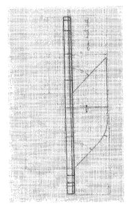
FIGS. 94-97 depict an instrument 70 according to the present invention
which may be utilized for creating a tibial cut in order to implant a
prosthesis 10
according to the present invention. The instrument 70 shown may be placed on
top
of the flattened tibial plateau and may be pinned or otherwise secured in
place, such
as using the illustrated hole 72. The instrument 70 also includes a tibial cut
guide 74
having a slot 76 which may be formed at an angle that corresponds to the angle
of the
keel of the prosthesis to be implanted. FIGS. 98-102 illustrate a modular
instrument
70 according to the present invention which may be utilized for creating a
tibial cut
in order to implant a prosthesis according to the present invention. In
particular, FIG.
99 is a top perspective view of the instrument of FIG. 98 where one portion of
the
tibial cut guide 74 has been removed. The modular instrument 70 may then be
assembled with different guide components for generating cuts for different
sizes and
locations of a keel to be inserted. FIGS. 103-105 depict an instrument 78
according
to the present invention for sizing a tibial cut, so as to ensure that the cut
has been
made correctly for the prosthesis to be implanted. Lastly, FIGS. 106-109
depict an
impactor 80 according to the present invention in contact with a prosthesis 10
according to the present invention shown with reference to a cross-section of
a tibia
T. In accordance with one aspect of the present invention, the impactor 80 may
be
configured to engage the prosthesis 10 toward the middle thereof, and the
handle 82
may have the ability to pivot as the prosthesis 10 is being inserted.
While embodiments of the invention have been illustrated and
described, it is not intended that these embodiments illustrate and describe
all possible
forms of the invention. Rather, the words used in the specification are words
of
-29-
CA 02684759 2014-10-08
description rather than limitation, and it is understood that various changes
may be
made without departing from the scope of the invention.
-30-