Note: Descriptions are shown in the official language in which they were submitted.
CA 02684961 2009-10-21
WO 2008/156916 PCT/US2008/061442
1
ARTIFICIAL NAILS INCLUDING APPLICATION TABS
FIELD OF THE INVENTION
[0001] The present invention relates to human nail decorations, and more
specifically the invention pertains to structure and methods for placement of
preformed
artificial nails and tips for adherence to human nails.
BACKGROUND OF THE INVENTION
[0002] For various aesthetic reasons, many individuals wish to possess
elongated
fingernails or fingernails having a more finished or polished appearance.
However,
some are unable or unwilling to grow their own natural fingernails out to the
desired
length. Alternately, they may not have the time, skill, or financial
wherewithal to
maintain or obtain a more finished appearance that may result from well
manicured
and/or polished nails. As a result, entire industries have developed around
the artificial
supplementation and enhancement of natural nails. Such enhancements may range
from
manicuring and polishing of natural fingernails to individually building
artificial nails
on the natural nail and nail form from an acrylic powder and liquid which
chemically
bond to the nail surface as the artificial nail is built. Between these two
extremes, are
preformed, artificial nails that are glued or otherwise bonded to a person's
own naturally
occurring fingernails. Such nails are readily available to a wide range of
users through
drug and department stores. Such preformed artificial nails may be clear or
opaque,
and/or prepolished and/or decorated to provide the desired appearance.
[0003] Artificial nails are commonly made from molded thermoplastic and are
available in a wide range of lengths and styles. One broad category of an
artificial nail
style is the full nail form. As its name implies, the full nail form simulates
the entire
human fingernail and includes a proximate edge intended to overlay
substantially the
entire nail bed and a distal free edge which is intended to extend beyond the
fingertip of
the wearer. The proximate edge is shaped to be disposed substantially adjacent
or abut
against the cuticle of the finger. The distal free edge may have any of
various lengths
and shapes, such as oval, square, or flared, depending upon the desired look.
Preferably,
CA 02684961 2009-10-21
WO 2008/156916 PCT/US2008/061442
2
the artificial nail is sufficiently durable and rigid to withstand the hazards
inherent in its
use.
[0004] In contrast, nail tips do not simulate the complete nail, but,
rather, only the
free edge and, typically, a small extended portion to cover only a portion of
the nail bed
in order to facilitate attachment to the nail. In use, nail tips are secured
to the edge of
the nail bed adjacent the free edge and the tip only. Tips are often utilized
with the
construction of acrylic nails or gel nails.
[0005] Manufacturers typically provide users with a range of nail sizes,
e.g.,
identified by size numbers 0-9, to accommodate most nail sizes. Generally,
artificial
nails are packaged together in sets including a range of different sizes so
that the
purchaser receives differently artificial nails for their different fingers.
In addition to the
set of different sized artificial nails, the package may also include liquid
adhesive, peel-
off adhesive pads, and/or preplaced tacky adhesive for bonding the artificial
nails to the
purchaser's natural fingernails.
[0006] Artificial nails are provided in a variety of lengths ranging from
relatively
long nails having either a straight profile or arched profile, to relatively
short nails,
which more closely simulate well groomed natural nails. In placement of the
artificial
nail on a user's natural nail, the adhesive is typically applied either
directly to the user's
natural nail bed or to the nail bed portion of the artificial nail. The
artificial nail is then
placed on the user's natural nail bed with the proximal end of the artificial
nail disposed
at or near the user's cuticle, and pressure is applied to ensure the desired
adhesion of the
artificial nail to the user's natural nail. Inasmuch as the adhesive used in
placing
artificial nails is generally tacky, it is difficult to make adjustments to
the position of the
artificial nail on the natural nail once initial placement is made. Attempts
to reposition
the artificial nail relative to the natural nail or to remove and replace the
artificial nail
may result in either a substandard appearance to the artificial nail, or time
consuming
additional cleaning of the artificial nail and repetition of the placement
process. As a
CA 02684961 2009-10-21
WO 2008/156916 PCT/US2008/061442
3
result, it is important that the artificial nail be placed at the desired
position on the
natural nail at the first attempt so as to avoid the need to remove and
reposition the nail.
[0007] Longer artificial nails typically extend well beyond the free edge
of the user's
natural nails. Consequently, in placing relatively long artificial nails on
the user's
natural nails, one may generally utilize the extended free edge of the
artificial nail to
hold the artificial nail prior to placement, and to manipulate and accurately
position the
artificial nail on the user's nail bed. When utilizing smaller artificial
nails, however, the
free edge is very short, and does not extend far beyond the user's natural
nail or finger
tip, if at all. Accordingly, such short nails can be particularly difficult to
accurately
place on the user's natural nail by simply grasping the artificial nail using
one's fingers.
[0008] As a result, manufacturers have proposed various tools to allow for
holding
and placing artificial nails during application. One such tool is comprises an
elongated
rod with a tacky adhesive pad or tape at the end of the tool to grip the
artificial nail, such
as the tools shown in U.S. Patent 6,220,250 to Park and the tool marketed by
Sally
Hansen . This tacky, adhesive pad, however, has proven unreliable in use,
however,
inasmuch as the retaining force exerted by the adhesive on the artificial nail
typically
deteriorates over time such that it does not exert a consistent retaining
force on the
artificial nail. Moreover, should the adhesive pad become contaminated with
dust or the
like, it becomes generally useless in that it does not exhibit adequate force
to retain a
series of nails for placement.
[0009] Another such tool is shaped like a concave shovel with a shorter
opposing lip
that is disposed parallel to the shovel such that a small slot or gap is
formed between the
inside surface of the shovel and the lip, as shown in U.S. Patent D441,134 to
Manzione
and marketed by Uptown Nails, LLC. In use, the outer, arched surface of the
artificial
nail is disposed against the inside surface of the shovel with the free edge
of the
artificial nail disposed in the gap between the lip and the shovel. This tool
likewise
exhibits deficiencies. While the "shovel" tool does not deteriorate with use,
it is
cumbersome to utilize. Should the gap between the shovel and lip be
sufficiently small
CA 02684961 2009-10-21
WO 2008/156916 PCT/US2008/061442
4
to exert a retaining force on the artificial nail, the user will typically be
required to exert
an external downward, retaining force on the artificial nail when it is placed
against the
natural nail in order to facilitate release of the artificial nail by the
tool. Inasmuch as the
user's free hand grasps the tool, the user must typically use a different
finger from the
placement hand to exert a retaining force the placed artificial nail to
facilitate release of
artificial nail from the tool. Conversely, if the tool does not exert adequate
retaining
force to hold the artificial nail during the placement process, the tool may
allow artificial
nail to move within the gap, making accurate placement of the artificial nail
against the
natural nail significantly more difficult.
[0010] The assignee of the present invention has proposed a tool that
utilizes a small
suction cup disposed at the distal end of an elongated rod. In applying an
artificial nail
to a natural nail, the user places the suction cup on the upper surface of the
artificial nail
and expels any air trapped between the cup and the nail. The user then
utilizes the tool
to position the artificial nail on the natural nail. The suction cup provides
sufficient
force to retain the nail during placement, yet that force is overcome by the
tackiness of
the adhesive or the adhesive bond between the artificial nail and the natural
nail once
properly placed. The tool is disclosed in greater detail in PCT Publication
W006/062963A.
[0011] Manufacturers have likewise proposed severable protrusions that
extend from
one or more edges of the artificial nail themselves. The protrusions are
utilized to place
the artificial nail and then severed from the nail once proper placement has
been
achieved. For example, U.S. Patent 6,892,736 to Chinn et al. includes a tab
that extends
from the distal edge of the nail. Unfortunately, however, the Chinn tab is not
ergonomic, and is difficult and cumbersome to use. As may be seen in FIG.11,
the
Chinn tab 13 must typically be held between a finger 14 and the thumb 15 of
the
applying hand 16, the thumb 15 being disposed either below or above the plane
of the
artificial nail 17. Accordingly, the user's hand 16 is in an awkward position
relative to
the receiving finger. As a result, typically, either a separate finger from
the receiving
hand must be used to securely seat the artificial nail 17 in position on the
natural nail
CA 02684961 2009-10-21
WO 2008/156916
PCT/US2008/061442
during severing of the nail tab 13, or the user must hold the artificial nail
17 in position
until such time as the adhesive fully cures. Similar difficulties are
encountered in
placing the nails disclosed in other references, such as U.S. Patent 5,005,595
to Aylott,
for example.
[0012] As a result, it is desirable to provide a nail placement arrangement
that
overcomes these shortcomings of the prior art to provide for accurate and
reliable,
repeatable placement of artificial nails.
BRIEF SUMMARY OF THE INVENTION
[0013] The invention provides a nail application tab that extends generally
from the
distal end of the nail, the body of the application tab being disposed at an
angle to a
plane including the top or bottom surface of the artificial nail. Typically,
the application
tab is disposed at approximately a normal angle to a plane containing the top
surface of
the artificial nail when taken along the centerline, although the tab may be
disposed at
an alternate angle, preferably greater than 30 . The application tab may
extend from
one or more of any of the distal edge, or top or bottom surface of the nail.
After
placement, the application may be severed by any appropriate means. Separation
may
be facilitated by a weakened area provided by, for example, a perforation, an
area of
reduced thickness, a score line, or a reduced cross-sectional area.
[0014] The extension of the tab or other gating feature used in the molding
of the
artificial nail may be particularly advantageous in de-gating or separating
the nail from
the tab, tree or other molding structure.
[0015] In order to place the artificial nail on a natural nail, the user
may grasp the
generally vertically extending tab with the thumb and middle finger of the
applying
hand to apply the artificial nail to the natural nail of the receiving hand or
a foot. Once
the nail is placed, while continuing to hold the application tab, the user
uses the index
finger of the applying hand to lightly press the artificial nail into a final
secured position
on the receiving natural nail until such time as the adhesive secures the
artificial nail in
CA 02684961 2009-10-21
WO 2008/156916 PCT/US2008/061442
6
place. The user may then sever the application tab from the artificial nail by
any
appropriate means, such as snapping, tearing, or cutting. In this way, the
artificial nail
with tab provides ergonomic arrangement that facilitates nail placement with
one hand.
[0016] The kit may further include an adhesive, a towelette including a
cleaner, a
roughening surface, a stick, and/or a placement tool.
[0017] These and other objects and advantages of the invention will be
apparent to
those skilled in the art upon reading the following summary and detailed
description and
upon reference to the drawings.
BRIEF DESCRIPTION OF THE DRAWINGS
[0018] Figure 1 is a perspective view of a kit having exemplary contents,
including
an artificial nail according to teachings of the invention.
[0019] FIG. 2 is a perspective view of an artificial nail with application
tab
constructed in accordance with teachings of the invention.
[0020] FIG. 3 is top plan view of the artificial nail of FIG. 2.
[0021] FIG. 4 is a side elevational view of the artificial nail of FIGS. 2
and 3.
[0022] FIG. 5 is a perspective view of an alternate embodiment of an
artificial nail
with application tab constructed in accordance with teachings of the
invention.
[0023] FIG. 6 is a top plan view of the artificial nail of FIG. 5.
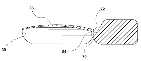
[0024] FIG. 7 is a side view of the artificial nail of FIGS. 5 and 6.
[0025] FIG. 7A is a cross-sectional view of the artificial nail of FIGS. 5-
7.
[0026] FIG. 8 is a top plan view of another alternate embodiment of an
artificial nail
with application tab constructed in accordance with teachings of the
invention.
CA 02684961 2009-10-21
WO 2008/156916 PCT/US2008/061442
7
[0027] FIG. 9 is a side cross-sectional view of the artificial nail of FIG.
8.
[0028] FIG. 10A and 10B are perspective views of the artificial nail of
FIGS. 2-4
during placement on a natural nail.
[0029] FIG. 11 is a perspective view of an artificial nail arrangement of
the prior art
during placement on a natural nail.
[0030] FIG. 12A is a partial cross-sectional view of an artificial nail and
gating
arrangement.
[0031] FIG. 12B is a cross-sectional view of another embodiment of an
artificial nail
and gating arrangement.
DETAILED DESCRIPTION OF THE INVENTION
[0032] Turning now to the drawings, wherein like reference numbers refer to
like
elements, there is illustrated in FIG. 1 a nail kit 18 comprising a package 20
containing a
plurality of preformed artificial nail assemblies. Each nail assembly
comprises an
artificial nail 22 which has a proximal end 30, adapted to be placed generally
adjacent
the user's cuticle, and a distal end 32 that is generally disposed at or
beyond the end of
the user's natural nail when properly placed. The areas between the proximal
and distal
ends 30, 32 of the artificial nail 22 generally define the nail bed portion 34
and the free
end 36, the nail bed portion 34 being adapted to be placed adjacent the user's
natural
nail bed and the free end portion 36 being adapted to extend beyond the end of
the
user's finger. The artificial nails 22 further include right and left side
edges 37, 38 with
the nail 22 having a generally arched contour between the side edges 37, 38
and a
generally less arched contour between the proximal and distal edges 31, 33.
[0033] The nail kit package 20 typically includes an outer covering 40,
here in the
form of a box, having at least one transparent portion 41 for viewing the
contents of the
package 20. The package 20 further includes an inner support housing 42 that
generally
retains the contents of the package 20 in position within the package 20. The
inner
CA 02684961 2009-10-21
WO 2008/156916
PCT/US2008/061442
8
support housing is typically formed of a polymeric material. The inner support
housing
42 generally includes a plurality of recessed areas 44, and additional
contents of the
package 20 may be retained in a rear open portion of the inner support housing
42.
[0034] In accordance with the invention, the artificial nail assembly
includes an
application tab arrangement 50 to ergonomically facilitate placement of the
artificial nail
22 on a natural nail. The tab arrangement 50 includes a body 52 for the user
to grasp
during placement, and a neck 54 that extends between the body 52 and the nail
22.
According to an important feature of the invention, at least a portion of the
body 52 is
disposed at an angle to a plane containing the upper or lower surface 39 of
the nail 22
generally along its centerline 23. Significantly, the portion of the body 52
disposed at
an angle to the plane must be sufficiently large to be grasped by a user
during placement
of the nail 22.
[0035] The neck 54 attaches the body 52 to the nail 22 at its distal end
32. While the
neck 54 may extend from the distal edge 33, as shown in FIGS. 2-4, it may
alternately
extend from the upper or lower surface 39 of the artificial nail 22 or a
combination of
the distal edge 33 and one or both of the upper or lower surfaces 39. As shown
in FIGS.
5-7, for example, the neck 60 may extend from the lower surface 39. It will be
appreciated by those of skill in the art that when the neck 60 is separated
from the nail
64, the neck 60 will not leave any sharp edges or points protruding from the
distal edge
66 of the nail 64. In this embodiment, the neck 60 extends from the lower
surface 39
proximate to the distal edge 66, while in the embodiment of FIGS. 8-9, the
neck 70 is
spaced back slightly from the distal edge 72 of the nail 86.
[0036] These advantages are likewise apparent in the absence of a nail tab,
that is,
when the gating structure 115, 116 for molding the artificial nail extends
from the lower
surface of the nail, as shown, for example in FIGS. 12A and 12B. The gating
structure
may include any structure known in the art, such as a nail tree, for example,
and the
nails and gating structure may be molded by any appropriate molding
techniques,
including those presently known in the art or developed in the future. Those
of skill in
CA 02684961 2009-10-21
WO 2008/156916 PCT/US2008/061442
9
the art will appreciate that in molding the nails and gating structure, a mold
cavity for
molding the gating structure provides fluid communication to the mold cavities
for
forming the lower surface such that the resulting molded gating structure
extends from
the lower surface of the molded nail.
[0037] Returning to the figures illustrating the nail tabs, according to a
feature of the
invention, once appropriately placed, the tab arrangement 50 may be separated
from the
nail 22 by any appropriate mechanism. For example, the neck 54 of the tab
arrangement
50 may include a weakened area, such as, for example, a thinned section 80
substantially adjacent the distal edge 33 of the nail 22, similar to the
arrangement shown
in FIGS. 2-4, a perforation 82, as shown, for example, in FIG. 7A, a
relatively small
cross-section 84 at the location where the neck 70 meets the nail 86, such as
is as shown,
for example in FIG. 9, a score line, or any combination of such structures.
While less
desirable, those of skill in the art will appreciate that the tab arrangement
50 could
alternately be severed from the nail 22 by a tool, such as scissors or a
blade.
[0038] Turning to FIGS. 10A and 10B, according to an important feature of
the
invention, a user may easily apply the artificial nail 22 to a natural nail
100 in a
coordinated and ergonomic manner. More specifically, when applying the
artificial nail
22 to a natural nail 100, the user may grasps the body 52 of the tab
arrangement 50
between the thumb 102 and middle finger 104 of the applying hand 106 to
position the
artificial nail 22 on the natural nail 100 of the receiving hand 108, as shown
in FIG.
10A. Once the user has placed artificial nail 22 on the natural nail 100,
while
continuing to hold the body 52 of the tab arrangement 50, the user may then
utilize the
index finger 110 of the applying hand 106 to place a retaining force on the
upper surface
of the situated artificial nail 22, as shown in FIG. 10B, in order to ensure
proper seating
of the artificial nail 22 and distribution of the adhesive. If desired, while
continuing to
apply a downward force, the user may further use the thumb 102 and middle
finger 104
of the applying hand 106 to separate the tab arrangement 50 from the
artificial nail 22,
should the arrangement 50 include a weakened area as the mechanism for
facilitating
CA 02684961 2009-10-21
WO 2008/156916
PCT/US2008/061442
separation. In this way, the user may easily and quickly apply a plurality of
artificial
nails to respective natural nails to obtain a polished, manicured appearance.
[0039] It will thus be appreciated by those of skill in the art that the
disposition of
the body 52 at an angle to the upper or lower surfaces of the artificial nail
22 provides
an ergonomic arrangement that is easily utilized to place the nail. The angled
disposition is as opposed to a tab in a generally continuous plane with the
nail, as
provided, for example, in U.S. Patent 6,892,736 to Chinn et al. or U.S. Patent
5,005,595
to Aylott. The angle must be sufficient to allow the user to comfortably grasp
the body
52 and place the nail 22. While a normal angle is generally preferable
inasmuch as it
allow the user to readily place the nail using either the left or right hand,
an angle of at
least 30 to either the top or bottom surface of the nail 22 will typically be
adequate to
facilitate grasping and placing the nail 22.
[0040] In order to further assist the user in artificial nail choice, at
least the body 52
of the tab arrangement 50 may be sufficiently wide to display information for
the user.
Thus, the tab 50 may include indicia 112 such as, for example, the size number
of the
accompanying nail, the name of the manufacturer, a trademark or tradename, the
nail
color or instructions. The indicia 112 may provided on the tab arrangement 50
by any
appropriate mechanism, such as, for example, molding the indicia into the
arrangement,
or printing the indicia thereupon. In this way, such indicia 112 may
facilitate the user's
choice of nail for application.
[0041] It will be appreciated that the preformed artificial nails 22
utilized in the nail
kit 18 may be of any appropriate design. For example, the invention may
likewise be
utilized in connection with a nail tip, as opposed to a full nail, as
illustrated in the
figures. Thus, for the purposes of this disclosure and the claims appended
hereto, the
term "nail" will be used to correspond to both a full nail and a nail tip.
Those of skill in
the art will appreciate that the nail tip is essentially the same as a full
nail with the
exception that the nail tip includes only a portion that is adapted to cover
only a distal
portion of the natural nail. Moreover, the nail kit may include additional
items, such as,
CA 02684961 2014-05-08
11
by way of example only, an appropriate adhesive, such as is shown in FIG. 1, a
rough or
emery type surface for buffing the natural nail prior to placement of the
artificial nail, a
towelette including an acetone or other substance to clean the nail prior to
placement, a
rosewood stick and/or an application tool for assistance during installation
of the
artificial nail onto the natural nail surface.
100421 While this invention has been described with an emphasis upon
preferred
embodiments, variations of the preferred embodiments can be used, and it is
intended
that the invention can be practiced otherwise than as specifically described
herein.
Accordingly, this invention includes all modifications encompassed within the
scope of
the invention as defined by the following claims.