Note: Descriptions are shown in the official language in which they were submitted.
CA 02684976 2011-08-30
1
BLOWOUT PREVENTER WITH BONNET MOVEMENT AND VALVE APPARATUS
The present invention relates to a blowout preventer.
A blowout preventer is generally used for preventing
a sudden rise in pressure in a fluid in a wellbore from
escaping the wellbore. A surge in pressure could cause
equipment above the well to fail and in a worst-case
scenario cause a blowout. When a sudden rise in pressure
is observed in the wellbore, a blowout preventer located
at the top of the wellbore is activated to either: isolate
the entire wellbore; or the annulus between a pipe or tool
string running therethrough and the wall of the wellbore.
In the formation of a wellbore, drilling mud is
circulated from the surface through a string of drill pipe
running in the wellbore to the drill bit and returns to
the surface in an annular passage defined by the string of
drill pipe and the wellbore or casing lining the wellbore.
If a sudden rise in pressure in the drilling mud is
observed, the blowout preventer is activated to prevent
the high pressure drilling mud escaping or damaging
equipment at the top of the well. Densifiers are added to
the drilling mud and circulated in the closed off well
until the pressure of the drilling mud in the wellbore
comes under control. The blowout preventer is then opened
and drilling continues in a normal manner.
In a variety of situations, blowout preventers are used to
control sub surface pressures that may adversely affect
equipment used in drilling oil and gas wells. Manual
mechanisms and pneumatic or hydraulic pressure are
employed to act on a piston to close or open ram sealing
CA 02684976 2009-10-22
WO 2008/132496 PCT/GB2008/050253
- 2-
elements. Often hydraulic actuation is used since the
required closing forces are relatively high. Hydraulic
actuation force is applied to a cylinder containing a
piston which in turn acts on a shaft having a ram element
connected thereto. In certain prior art blowout
preventer systems, a ram locking member is operable by
turning an exterior shaft extension projecting from the
blowout preventer. Alternatively the locking member is
movable automatically, for example, using known automatic
operator apparatus, for example, but not limited to known
POSLOCK apparatus available from National Oilwell
Varco, owner of the present invention.
US-A-5,575,452 co-owned with the present invention,
discloses, inter alia, a blowout preventer ram actuator
mechanism with a primary piston including an outer sleeve
portion which supports an independently movable locking
piston which has tapered surfaces, and locking segments
each engage one of a plurality of tapered locking rods
fixed to the actuating mechanism housing. U.S. Patent
7,195,224, co-owned with the present invention,
discloses, inter alia, blowout preventers having a main
body, a ram system with ram apparatus, a movement system
with movable shaft apparatus connected to the ram
apparatus, the ram apparatus movable from a first open
ram position to a second closed ram position, the movable
shaft apparatus including a locking shaft portion having
a tapered portion, a locking system for selectively
locking the ram apparatus in the closed position and
having locking member apparatus having a primary tapered
surface in contact with the locking shaft portion which
is movable with the so that the primary tapered surface
contacts the tapered portion of the locking shaft portion
to releasably lock the movable shaft apparatus.
CA 02684976 2009-10-22
WO 2008/132496 PCT/GB2008/050253
- 3-
In many prior ram-type blowout preventer systems,
once rams have been moved to contact a tubular, for
example, a pipe, the rams are locked in place by turning
a lock shaft connected to a ram shaft to which a ram is
connected. Rotating the lock shaft sufficiently to lock
a ram in position can often take a relatively long time.
Various prior blowout preventers have a main body
with a projecting member or operating/ cylinder "head"
through which the lock shaft extends. External threading
on the lock shaft threadedly engages internal threading
on the head. Rotation of the lock shaft with respect to
the head locks the ram shaft and the ram in a desired
position preventing the ram from disengaging from a pipe.
The head adds size and weight to the overall system and,
in some cases, enlarges the distance that a lock shaft
must travel to lock a ram in place. The head is designed
to be sufficiently large and massive to handle the
locking load, the load imposed on the ram shaft and the
lock shaft by force acting on the rams pushing them out
of engagement with a pipe (force from wellbore pressure
active on a ram shaft or rubber pressure forcing the rams
apart).
In certain prior blowout preventers in order to move
a ram out of engagement with a tubular and open a bonnet
or door, the bonnet must move the length of the ram plus
the length of the stroke of a ram operator. In certain
prior blowout preventers separate hydraulic circuits are
used for ram movement and for bonnet movement.
In accordance with the present invention, there is
provided a blowout preventer comprising a main body, a
ram apparatus movable within the main body to engage a
tubular, a hydraulic circuit apparatus for providing
fluid under pressure to operate the ram apparatus, a
CA 02684976 2009-10-22
WO 2008/132496 PCT/GB2008/050253
- 4-
bonnet movably connected to the main body for providing
access to the ram apparatus, characterised in that the
blowout preventer further comprises bonnet movement
apparatus and a valve apparatus, such that in use said
valve apparatus is used to selectively allow hydraulic
fluid to flow from said hydraulic circuit apparatus to
said bonnet movement apparatus to move said bonnet to
access the ram apparatus. Preferably, the ram apparatus
includes a ram block with tubular engaging structure, the
ram block and the tubular engaging structure having a
block length, the hydraulic circuit apparatus provides
fluid under pressure to disengage the tubular engaging
structure from a tubular and to move the ram block away
from the tubular, the bonnet movable by the bonnet
movement apparatus a bonnet distance from the main body
to provide access to the ram block. Advantageously, the
hydraulic circuit apparatus providing fluid for
disengaging the ram apparatus from a tubular, a portion
of said fluid for said disengaging useful for moving the
bonnet.
Preferably, the blowout preventer further comprises
a fluid flow channel between the bonnet movement
apparatus and the ram apparatus for allowing hydraulic
fluid to flow into the ram apparatus to ensure the ram
apparatus is in a retracted position before the bonnet
movement apparatus is activated. Advantageously, the
blowout preventer further comprises valve activation
apparatus for manually activating the valve apparatus to
open or close the bonnet. Advantageously , said bonnet
movement apparatus comprises a piston and cylinder.
Preferably, the piston has a bore, an annulus between
said piston and said cylinder and a channel through said
piston to allow hydraulic fluid to flow between the bore
CA 02684976 2009-10-22
WO 2008/132496 PCT/GB2008/050253
- 5-
and the annulus.
Preferably, the blowout preventer further comprises
a ring for selectively closing off said channel.
Preferably, the ring is slideable along the piston.
Advantageously, the ring is slid along the piston by
activation of the valve apparatus. Preferably, a shoulder
is located at one end of the cylinder, such that upon
extension of the piston, the ring abuts the shoulder and
is moved along the piston to reveal the channel.
Preferably, a tube is arranged within the bore,
advantageously, the tube is in fixed relation with the
cylinder.
Advantageously, the bonnet movement apparatus
comprises a second piston and cylinder. Preferably, the
first piston and cylinders arranged on a first side of
the bonnet and the second piston and cylinders arranged
on a second, opposing side of the bonnet. Advantageously,
the valve apparatus comprises a first valve of the first
piston and cylinder and a second valve on the second
piston and cylinder, the valve activation apparatus
comprising a fulcrum member on the bonnet, a rocker plate
mounted for rocking movement on the fulcrum member, the
rocker plate movable in a first direction to contact the
first valve to open the bonnet, the rocker plate movable
in a second direction to contact the second valve to
close the bonnet. Advantageously, the ram apparatus
includes tubular engagement apparatus and wherein
hydraulic fluid under pressure supplied for operation of
the ram apparatus to disengage the tubular engagement
apparatus is also used to open and close the bonnet.
The present invention also provides a method for
accessing a ram apparatus of a blowout preventer, the
blowout preventer comprising a main body, a ram
CA 02684976 2009-10-22
WO 2008/132496 PCT/GB2008/050253
- 6-
apparatus movable within the main body to engage a
tubular, a hydraulic circuit apparatus for providing
fluid under pressure to operate the ram apparatus, a
bonnet movably connected to the main body for providing
access to the ram apparatus, characterised in that the
method comprises the steps of using valve apparatus to
selectively allow hydraulic fluid to flow from the
hydraulic circuit apparatus to the bonnet movement
apparatus to move the bonnet to access the ram
apparatus.
The present invention also provides a blowout
preventer comprising a main body, a bonnet connected to
the main body, a ram apparatus comprising a ram shaft
movably disposed in the bonnet, the ram shaft having an
inner end for a ram block and an outer end movable in
said bonnet, a locking assembly for selectively locking
the ram shaft, characterised in that said locking
assembly comprises a locking head having a thread for
threadedly engaging an thread about an opening in said
bonnet, said locking head rotatable within the opening so
that the locking head abuts the outer end of the ram
shaft to releasably lock the ram shaft in position.
Preferably, the thread on the locking head is an external
thread and the thread about the opening is an internal
thread. Advantageously, the thread on the locking head is
an internal thread and the thread about the opening is an
external thread. Preferably, the bonnet is movably
connected to the main body.
Instead of moving the relatively long distance
through a head and through a main blowout preventer body
to lock a ram in place, the locking shaft of a locking
assembly in accordance with the present invention moves a
relatively shorter distance along the opening in the
CA 02684976 2009-10-22
WO 2008/132496 PCT/GB2008/050253
- 7-
bonnet (such as a door), to a final position abutting the
outer end of the ram shaft. The bonnet only needs to
open far enough to clear the ram block, i.e., the length
of the ram block. To open the bonnet with the ram
already off of a tubular, disengaged, the bonnet needs
to move only the length of the ram block - it needs only
to open a distance equal to the length of the ram block -
to expose the ram block with the bonnet open.
Advantageously, said locking head is rotatable with
respect to said ram shaft. Preferably, said locking head
has a shaft attached thereto, the shaft movably arranged
in or about said ram shaft. Preferably, the shaft is
rotatably fixed thereto, such that rotation of the shaft
rotates the locking head.
Advantageously, at least one spring is arranged
between said locking head and said ram shaft. Preferably,
the spring is tensioned upon activation of the ram
apparatus and urges the locking head against the thread
about the opening. Advantageously, the spring maintains
alignment of the thread on the locking head and the
thread about the opening in the bonnet. Advantageously,
the opening is larger than the diameter of the ram shaft.
Preferably, there is a seal arranged between the ram
shaft and the opening. Advantageously, a hole is
provided through the external end of the locking head for
receiving an item for manual rotation of the locking
assembly for selectively locking and unlocking the ram
shaft. Any suitable spring or springs, including, but not
limited to coil spring(s), wave springs, and/or
belleville washer springs.
The present invention also provides a method for
locking a ram apparatus of a blowout preventer in an
engaged position, the blowout preventer comprising a
CA 02684976 2009-10-22
WO 2008/132496 PCT/GB2008/050253
- 8-
main body, a bonnet connected to the main body, a ram
apparatus comprising a ram shaft movably disposed in the
bonnet, the ram shaft having an inner end for a ram block
and an outer end movable in said bonnet, a locking
assembly for selectively locking the ram shaft,
characterised in that the locking assembly comprises a
locking head having thread and a thread about an opening
in said bonnet, the method comprising the steps of
activating said ram apparatus, and rotating said locking
head to engage the thread of the locking head with the
thread about the opening until the locking head abuts the
outer end of the ram shaft to releasably lock the ram
shaft in position.
The present invention also provides a blowout
preventer comprising a main body, a bonnet connected to
the main body, a ram apparatus comprising a ram shaft
movably disposed in the bonnet, the ram shaft having a
member extendible therefrom, said member passing through
an opening in said bonnet said member having a head, such
that upon activation of the ram apparatus, the ram shaft
moves in the main body to engage a pipe, the head and
member are inhibited from moving, the head is then locked
in place to inhibit said ram shaft from retracting from
said engagement with said pipe.
Preferably, the locking head comprises a thread and
a corresponding thread about the opening in said bonnet.
The blowout preventer may be any of the following
types: a pipe ram; blind ram; and shear ram. The blowout
preventer may be of any size, such as small size suitable
for coiled tubing; standard size for casing sizes from
5cm (2 inch) to 1.2m (48 inch).
CA 02684976 2009-10-22
WO 2008/132496 PCT/GB2008/050253
- 9-
For a better understanding of the present invention,
reference will now be made, by way of example, to the
accompanying drawings, in which:
Figure 1 is a perspective view of a blowout
preventer in accordance with the present invention;
Figure 2 is a cross-section view of the part of the
blowout preventer shown in Figure 1;
Figure 3 is a cross-section view of the part of the
blowout preventer shown in Figure 2 showing a first step
in a method of its operation;
Figure 4 is a cross-section view of the blowout
preventer shown in Figure 2 showing a second step in a
method of its operation;
Figure 5 is a cross-section view of the blowout
preventer shown in Figure 2 showing a third step in a
method of its operation;
Figure 6 is a cross-section view partially in
schematic form of part of the blowout preventer shown in
Figure 1, shown with a bonnet in an open position and
with an optional rocker plate and with a hydraulic
control circuit; and
Figure 7 is a cross-section view partially in
schematic form of part of the blowout preenter shown in
Figure 1, shown with the bonnet closed and with an
optional rocker plate and with a hydraulic control
circuit.
Figure 1 shows a blowout preventer 10 in accordance
with the present invention with bonnets 12 each movable
with respect to a main body 14. A ram 20 on a ram shaft
30 projects from each bonnet 12, as shown in Figure 2.
An outer end 72 of a torquing shaft 70 of a locking
assembly 60 in accordance with the present invention is
outside each bonnet 12.
CA 02684976 2009-10-22
WO 2008/132496 PCT/GB2008/050253
- 10-
A piston 36 connected to the ram shaft 30 moves
within a chamber 19 to move the ram shaft 30 so that the
ram 20 can engage a tubular. Power fluid enters the
chamber 19 via an inlet and exits via an outlet (see
Figure 6).
Part of the torquing shaft 70 is disposed within a
channel 34 in the ram shaft 30. Springs 74 abut a stop
76 at one end of the torquing shaft 70 and a stop 78 at
another location on the torquing shaft 70 to bias a
locking shaft 62 inwardly and to maintain alignment of
threads 64 on the exterior of the locking shaft 62 and
interior threads 18 of a channel 16 in the bonnet 12.
The torquing shaft 70 is secured to the locking shaft 62.
A pin 68 in a recess 69 of the locking shaft 62 maintains
the position of the locking shaft 62. A seal gland 38
encompasses the ram shaft 30 and seals across the channel
16.
A portion of the torquing shaft 70 extends out
through a channel 66 in the locking shaft 62. A hole 71
through the torquing shaft 70 provides a location for a
tool, for example, a handwheel or used to manually rotate
the locking assembly 60 or a motor used to rotate the
locking assembly 60.
As shown in Figure 3, in use, an operator device,
not shown, allows hydraulic fluid to flow into chamber 19
behind the piston 36 to move the ram 20 to engage a pipe
P. The ram 20, ram shaft 30, piston 36, and locking
assembly 60 have moved (to the right in Figure 3). The
locking shaft 62 has moved to the entrance to the channel
16. The locking shaft 62 is inhibited from further
movement towards the pipe P by a top of a thread formed
in the body of the bonnet 12. Figure 4 shows the ram
shaft 30 moved further to a point at which the ram 20
CA 02684976 2009-10-22
WO 2008/132496 PCT/GB2008/050253
- 11-
meets or engages the pipe P, with the locking shaft 62
stationary with respect to the bonnet 12. Movement of the
torquing shaft 70 relative to the locking shaft 62 has
compressed the springs 74.
To lock the ram shaft 30 in place, the locking shaft
62 rotates as the spring 74 decompresses to move the
locking shaft 62 along the thread in the body of the
bonnet 12 to abut end 32 of the ram shaft 30 (as shown in
Figure 5). The locking shaft 62 can be rotated by a
handle or motor attached to the end 70 to facilitate
rotation of the locking shaft until it contacts the end
32 of the ram shaft 30. The locking shaft 62 moves the
distance from the entrance to the channel 16 to the end
32 of the ram 30 to achieve the releasable lock of the
ram shaft 30.
Figure 6 shows a bonnet 12 of the blowout preventer
10 with the ram 20 in a retracted open position
disengaged from pipe P. A telescopic arm 8 is arranged on
each side of the ram shaft 30 in a telescopically
extended position, the bonnet 12 situated away from the
main body 14 of the blowout preventer 10 to reveal the
ram 20. Retraction of the telescopic arms 8 moves the
bonnet 12 toward the main body 14, so that locking bars
(not shown) can be inserted into a hole formed between
the bonnet 12 and the main body 14 to hold the bonnet in
place. This aspect is described in the applicants PCT
Publication Number WO 2005/106188. As shown in Figures 1
and 6, the blowout preventer 10 includes an optional
rocker plate 100 which is used to contact and manually
activate a valve 102 or 104 to open (activate valve 102)
or close (activate valve 104) the bonnet 12. It is
within the scope of the present invention to use any
suitable known structure or apparatus to manually
CA 02684976 2009-10-22
WO 2008/132496 PCT/GB2008/050253
- 12 -
activate the valves 102, 104, including, but not limited
to, handwheels, wrenches, and/or levers (levers on the
valves, levers adjacent the valves).
The telescopic arms 8 comprise a cylinder 119a fixed
to the bonnet 12, a piston 112,114 slidably arranged in
the cylinder 119a, each piston 112,114 having a central
bore 112a therethrough and a tube 117 fixed with respect
to the cylinder 119a and slidably arranged in the central
bore 112a with an annulus 117b therebetween.
A control valve 110 (for example, a typical 3-way
directional control valve) controls the flow of fluid
under pressure from a fluid source 106 to a ram-open
piston 112 with a channel 112a and to a ram-close piston
114 with a channel 114a. A control system 120 controls
the valve 110. Vented fluid flows to tank 116.
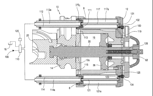
As shown in Figure 7, the ram 20 is not in a
retracted position; the bonnet 12 is open; the piston 36
has had fluid applied to it to move the bonnet 12 open;
with fluid applied to the pistons 112 and 114. The fluid
flowed from the source 106, through the valve 110; and
either through the end of piston 112 or through port 119
in the bonnet 12; to and through a tube 117 and into
channel 112a, through annulus 117b and through a channel
111 in the piston 112; into an annulus 118a between the
piston 112 and cylinder 119a and flows through a channel
113; and into the chamber 19 to pressurize the piston 36
and ensure it is in the retracted position.
When it is desired to move the bonnet 12 away from
the main body 14 to access the ram 20, the rocker plate
100 is pushed, which depresses valves 102, 104 moving a
ring 118 to block the flow of hydraulic fluid from
entering the annulus 118a, so that the piston extends
from the cylinder 119a to move the bonnet 12 away from
CA 02684976 2009-10-22
WO 2008/132496 PCT/GB2008/050253
- 13-
the main body 14. As shown in Figure 6, when the piston
reaches its fullest extent, the ring 118 is pushed back
by shoulder 119c of the cylinder 119a and the channel 111
is blocked by the shoulder 119c, to maintain the piston
in the extended position maintaining the bonnet 12 away
from the main body 14. When it is desired to close the
bonnet 12, the bonnet 12 is pushed a short distance until
hydraulic fluid can flow from channel 111 against the
shoulder 119c, retracting the piston 12, whereupon
hydraulic pressure facilitates movement of the bonnet 12,
if hydraulic pressure is maintained.
The rocker plate 100 may move in see-saw fashion on
a fulcrum member 126. Depressed one way, the rocker
plate 100 contacts and activates the valve 104 to vent
fluid that is holding the bonnet 12 open, permitting the
bonnet 12 to be closed.
Pushing the rocker plate against the valve 102
allows pressurized fluid from the chamber 19 into the
chambers 117a, 121a, extending the pistons 112, 114 so
that the bonnet 12 can be opened. Figure 7 shows the
bonnet 12 closed.
To close the bonnet 12 so that the ram 20 can be
moved to contact a pipe, the valve 110 is shifted so that
fluid from the channel 112 is vented to tank 116 and
fluid from the source 106 is sent to and through the
channel 114; to and through a channel 121; to and through
a channel 123; past the valve 104; to and through a
channel 125; and into the chamber 19 on the other side
(the right side as viewed in Figure 6 of the piston 36).
This fluid moves the piston 36 towards a bonnet plate
12a, thereby moving the ram shaft 30 to move the ram 20
to contact a pipe.
In blowout preventers in accordance with the present
CA 02684976 2009-10-22
WO 2008/132496 PCT/GB2008/050253
- 14 -
invention, for example, as described above and shown in
Figures 1 to 7, the fluid under pressure used for ram
opening (moving a ram 20 away from a tubular) is also
used to open and close the bonnet 12. The bonnet 12
needs to move (open) only a "bonnet distance" - a length
sufficient to clear the ram 20 with respect to the body
14, for example, the length of a ram block 20a (see
Figure 2) plus a small increment to provide access to the
block.