Note: Descriptions are shown in the official language in which they were submitted.
CA 02685712 2009-11-10
HITCH BALL ASSEMBLY
FIELD OF INVENTION
100011 The present invention relates generally to a towing assembly and, more
particularly, to a
dual hitch ball assembly.
BACKGROUND
100021 Many vehicles, such as trucks, are designed to transport freight,
goods, merchandise,
personal property, and other such cargo. Typically, a towed vehicle or trailer
may be connected
to a towing vehicle by way of a hitch assembly or coupling member. The hitch
assembly may
include a ball hitch or member secured to the towing vehicle and a ball socket
or coupling
mechanism secured on the towed vehicle or trailer.
[0003] For example, the ball socket may be mounted over the hitch ball thereby
allowing the
trailer to pivot behind the towing vehicle. Ball and socket-type towing
mechanisms may be used
on a wide variety of vehicles, such as automobiles, SUVs, trucks, tractors,
and the like. The
socket-to-hitch ball connection may allow for relative movement between the
towing vehicle and
the trailer as the towing vehicle makes turns, traverses uneven or rough
terrain, and passes along
inclining and declining roadways.
[0004] The socket structure of a coupler mechanism is typically affixed to the
trailer or towed
vehicle. Generally, the socket or coupler may be secured to a tongue or
extension of the frame of
the trailer. Often, the sockets of trailers may be of various sizes whereby
hitch ball members of
different sizes and diameters may be required for this purpose. As a result,
it is not uncommon
for different types of trailers to be equipped with sockets that may be
adapted for use with hitch
balls of different sizes and diameters. As the sockets are frequently
permanently attached to the
1
CA 02685712 2009-11-10
towed vehicle, the hitch ball of the towing vehicle must be removed and
replaced with a hitch
ball corresponding in size to the desired socket of the trailer. Removing the
hitch ball and
replacing the hitch ball with another sized hitch ball is inconvenient and
time consuming for the
user.
[0005] For example, such hitch balls may typically be provided with a threaded
mounting shank
that may be inserted through an aperture in a hitch bar located on the towing
vehicle. The hitch
ball may be secured to the hitch bar with a nut and locking washer. This is
typically inconvenient
for the user, as the user may be required to stoop or lay on the ground in
order to secure or
remove the hitch ball from the hitch bar. This may be particularly frustrating
if the ground is wet
or muddy. The user must then attach the hitch ball corresponding in size to
the given socket in
order to complete the hitch ball replacement.
[0006] As is known, hitch balls may be of various sizes and diameters.
Typically, there have
been several industry standard sizes (e.g., 1 7/8 inch, 2 inch, 2 1/4 inch and
2 5/16 inch in
diameter) that may be in frequent use. As a result, it is not uncommon for a
single towing vehicle
to be used to tow various trailers wherein those trailers may be equipped with
socket or coupler
assemblies that may be adapted for operative connection with the hitch balls
of different
diameters.
[0007] Current hitch assemblies may have deficiencies regarding the
construction of the hitch
ball and the hitch bar. Typically, the hitch ball may be secured to the hitch
bar by inserting the
shaft integrally formed with the hitch ball into an aperture located in the
hitch bar and then
securing the shaft with use of a fastener. Therefore, there is a need in the
art for an improved
dual hitch ball assembly that is easily interchangeable in order to be able to
connect to different
2
CA 02685712 2009-11-10
sized sockets. There is also a need for improved fabrication of the hitch bar
to reduce costs as
well as to improve the strength and durability of the hitch bar construction.
SUMMARY
[0008] A dual hitch ball assembly is described. The dual hitch ball assembly
may couple a
towing vehicle to a towed vehicle. The hitch ball assembly may include a hitch
bar, a base
member and at least one hitch ball. The hitch bar may include a first end and
a second end,
wherein the first end may be capable of being removably secured to a hitch
receiver on the
towing vehicle. The base member may be located on the second end of the hitch
bar. A first hitch
ball may be located on a side of the base member, wherein the first hitch ball
may be capable of
being coupled with the towed vehicle. A second hitch ball may be located on an
opposite side of
the base member, wherein the second hitch ball may be capable of being coupled
with the towed
vehicle. The hitch balls may have different diameters. The hitch bar may also
include at least one
webbed area. The hitch bar and the hitch balls may be a one-piece integrally
formed component.
3
CA 02685712 2009-11-10
DESCRIPTION OF THE DRAWINGS
[0009] Objects and advantages together with the operation of the invention may
be better
understood by reference to the following detailed description taken in
connection with the
following illustrations, wherein:
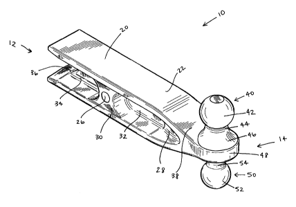
[0010] Figure 1 illustrates a perspective view of a dual hitch ball assembly.
[0011] Figure 2 illustrates another perspective view of the dual hitch ball
assembly.
[0012] Figure 3 illustrates a first side view of the dual hitch ball assembly.
[0013] Figure 4 illustrates a second side view of the dual hitch ball
assembly.
[0014] Figure 5 illustrates a top view of the dual hitch ball assembly.
[0015] Figure 6 illustrates a bottom view of the dual hitch ball assembly.
[0016] Figure 7 illustrates a front view of the dual hitch ball assembly.
[0017] Figure 8 illustrates a rear view of the dual hitch ball assembly.
DETAILED DESCRIPTION
[0018] Reference will now be made in detail to exemplary embodiments of the
present
invention, examples of which are illustrated in the accompanying drawings. It
is to be understood
that other embodiments may be utilized and structural and functional changes
may be made
without departing from the respective scope of the invention. As such, the
following description
is presented by way of illiustration only and should not limit in any way the
various alternatives
and modifications that may be made to the illustrated embodiments and still be
within the spirit
and scope of the invention.
4
CA 02685712 2009-11-10
[0019] A dual hitch ball assembly 10 is shown in Figures 1-8. The dual hitch
ball assembly 10
may be removeably secured to a hitch receiver (not shown). The hitch receiver
may be located
on a towing vehicle, such as an automobile, truck, SUV, or the like. The dual
hitch ball assembly
may be easily interchangeable so that it may be connected to different sized
sockets that may
be located on a variety of towed vehicles.
[0020] The dual hitch ball assembly 10 may include a hitch bar 20 and one or
more hitch ball
members 40, 50 (Figures 1-4). For example, the hitch ball assembly 10 may
include two hitch
ball members 40, 50. The hitch ball assembly 10 may also include a first end
12 and a second
end 14. The hitch bar 20 may be generally located towards the first end 12 of
the hitch ball
assembly 10 and extend towards the second end 14. The hitch ball members 40,
50 may be
generally located near the second end 14 (Figures 1 and 2).
[0021] The hitch bar 20 may be of any appropriate shape or size, such as a
generally rectangular,
tubular, cylindrical, or I-beam shape. The hitch bar 20 may be fabricated out
of any appropriate
material or process, such as being investment cast, cast, molded, forged, or
otherwise formed as a
single component. Fabricating the hitch bar 20 as a single integral component
may reduce costs
as well as to improve the strength and durability of the hitch bar 20
construction.
[0022] The hitch bar 20 may be connected to a vehicle. In one example, the
hitch bar 20 may be
connected to a hitch receiver mounted to a vehicle. The hitch receiver may be
attached to the
vehicle by any appropriate means, such as by being welded to the frame of the
vehicle, secured
under the bumper of the vehicle, or connected to the vehicle by other
appropriate means. The
hitch receiver may have an opening (not shown) that may be sized and shaped
similar to that of
the hitch bar 20, whereby the hitch receiver may be configured to receive the
hitch bar 20. The
hitch bar 20 may be shaped and sized so that it may be inserted into the hitch
receiver.
5
CA 02685712 2009-11-10
[0023] For example, the hitch bar 20 may be of a shape and size that
corresponds to the shape
and size of the hitch receiver. The hitch bar 20 may be secured to the hitch
receiver by any
appropriate means, such as by fasteners or the like. The hitch bar 20 may be
inserted into the
hitch receiver lengthwise and extend outward from the hitch receiver for
connection to the towed
vehicle. In addition, the hitch bar 20 may be a weight distributing hitch bar.
Utilizing a weight
disturbing hitch bar may distribute part of the trailer's hitch weight from
the towing vehicle's rear
axle to the towing vehicle's front axle and to the trailer's axles.
[0024] The hitch bar 20 may be of a general I-beam construction. The hitch bar
20 may include
an upper surface 22 and a lower surface 22. The upper and lower surfaces 22
may be generally
planar (Figures 1 and 2). For example, the hitch bar 20 may have a height H1
located at a first
end 12 of the hitch bar 20 and a height H2 at an opposite second end 14 of the
hitch bar 20
(Figures 4 and 7). The height H1 may substantially correspond to the height of
the hitch receiver.
The height H1 may greater than the height H2.
[0025] The hitch ball assembly 10 may also include a notched portion 36, a
narrow portion 38,
and a ball member base portion 48 (Figures 1-4). The notched portion 36 may be
of any
appropriate shape or size, such as a generally semi-circular, semi-ovular or
semi-rectangular
shape. The notched portion 36 may be located at any appropriate position, such
as adjacent the
first end 12 of the hitch bar 20. The notched portion 36 may also be located
and extend between
the upper and lower surfaces 22 of the hitch bar 20. By removing some of the
material at the first
end 12, the notched portion 36 may allow the first end 12 of the hitch bar 20
to flex thereby
reducing stresses in the hitch receiver.
[0026] The narrow portion 38 may be of any appropriate shape or size, such as
a generally
ovular or triangular shape. The narrow portion 38 may be located at any
appropriate position,
6
CA 02685712 2009-11-10
such as adjacent the second end 14. The narrow portion 38 may be located
wherein the upper and
lower surfaces 22 being to converge towards one another (Figures 1-4). The
ball member base
portion 48 may be of any appropriate shape or size, such as a generally
circular, ovular or
rectangular shape. The base portion 48 may be located at any appropriate
position, such as near
the second end 14 of the hitch ball assembly 10 (Figures 5 and 6). As the two
surfaces 22, 24
continue to converge past the narrow portion 38, they begin to become one as
the base portion
48. The base portion 48 may provide a base for the hitch ball members 40, 50
to be mounted to
(Figures 1-4 and 7).
[0027] The hitch bar 20 may include one or more attachment apertures. For
example, the hitch
bar 20 may include two attachment apertures 24, 26. The apertures 24, 26 may
be of any
appropriate shape or size, such as a generally circular, ovular or rectangular
shape. The apertures
24, 26 may be of a similar shape and size or the apertures 24, 26 may be of
differing shapes and
sizes. The apertures 24, 26 may be located at any appropriate position on the
hitch bar 20, such
as along the general center of the hitch bar 20. The first aperture 24 may be
located near the
second end 14 and adjacent the hitch ball members 40, 50. The second aperture
26 may be
located towards the first end 12.
[0028] The attachment apertures 24, 26 may secure the hitch bar 20 to the
hitch receiver. The
hitch receiver may include apertures (not shown). The apertures of the hitch
receiver may be
configured to align with the attachment apertures 24, 26 in the hitch bar 20
when the hitch bar 20
is inserted into the hitch receiver. When the apertures 24, 26 of the hitch
bar 20 are aligned with
the apertures of the hitch receiver, the hitch bar 20 may be secured in place
by inserting a
fastener, such as a pin (not shown), through the aligned apertures. The
apertures 24, 26 may also
be used for attaching any appropriate type of accessory to the hitch bar 20,
such as a pintle
7
CA 02685712 2009-11-10
accessory (not shown). For example, use of a pintle hook may allow a user to
tow a trailer that
has a lunette ring.
[0029] The hitch bar 20 may include at least one webbed area. For example, the
hitch bar 20
may include two webbed areas 32, 34. The webbed areas 32, 34 may be of any
appropriate shape
or size, such as generally ovular, rectangular or oblong shapes. The webbed
areas 32, 34 may be
of a generally similar or differing shapes and sizes. For example, the webbed
areas 32, 34 may be
indentations or recesses located in the hitch bar 20 (Figures 1 and 2).
[0030] The webbed areas 32, 34 may reduce the amount of material used to
manufacture the
hitch bar 20. In addition, when the hitch bar 20 is molded or cast, the webbed
areas 32, 34 may
assist in removing the hitch bar 20 from the mold or casting. The hitch bar 20
may have a width
WI along the general length of the hitch bar 20 and a W2 along the webbed
areas 32, 34 (Figure
8). The width W2 at the webbed areas 32, 34 of the hitch bar 20 may be less
than the maximum
width W1 of the hitch bar 20. For example, the width W2 of the hitch bar 20 at
the webbed areas
32, 34 may be the minimum width of the hitch bar 20.
[0031] The webbed areas 32, 34 may be located at any appropriate position on
the hitch bar 20.
For example, the first webbed area 32 may be located towards the second end
14. The first
webbed area 32 may also be located between the first aperture 24 and the
second aperture 26
(Figures 2-4). The second webbed area 34 may be located towards the first end
12. For example,
the second webbed area 34 may be located between the second aperture 26 and
the notched
portion 36 (Figures 1-4).
[0032] The hitch bar 20 may also include one or more protruding or thicker
sections. For
example, the hitch bar 20 may include two thicker sections 28, 30. The thicker
sections 28, 30
may be of any appropriate shape or size, such as a generally rectangular or
triangular shape. The
8
CA 02685712 2009-11-10
thicker sections 28, 30 may be of a generally similar shape and size or may be
of differing shapes
and sizes. For example, the thicker sections 28, 30 may be protrusions or
bulges located in the
hitch bar 20 (Figures 1 and 2). The thicker sections 28, 30 may be of a width
between the width
W1 of the hitch bar 20 and the width W2 of the webbed portions 32, 34.
[0033] The first thicker section 28 may be located towards the second end 14
and adjacent the
narrow portion 38. The first thicker section 28 may also be located between
the base member 48
and the webbed portion 32. The second thicker section 30 may be located
towards the first end
12 and between the webbed portions 32, 34. In addition, the apertures 24, 26
may be located
within the thicker sections 28, 30 whereby the thicker sections 28, 30 may
provide additional
material and strength to the apertures 24, 26.
[0034] The ball members 40, 50 may be of any appropriate shape or size, such
as a generally
spherical shape. The ball members 40, 50 may be of any appropriate or
conventional size. For
example, the ball members 40, 50 may be shaped for insertion into a
corresponding socket of the
trailer to be towed. The ball members 40, 50 may be of different sizes and
diameters, such as
different standard sized hitch balls (Figures 5 and 6). In a non-limiting
example, the ball
members 40, 50 may have a diameter of 1 7/8 inches, 2 inches, or 2 5/16
inches.
[0035] The ball members 40, 50 may be integrally formed with the hitch bar 20
or may be
separate, removable components that may be secured to the hitch bar 20 by any
appropriate
means, such as welding, fasteners, or the like. For example, the hitch bar 20
and the ball
members 40, 50 may all be of a one-piece, integrally formed component. While
the hitch ball
assembly 10 is shown and described as having two hitch ball members 40, 50, it
is to be
understood that there may be any appropriate number of hitch ball members 40,
50 of any
9
CA 02685712 2009-11-10
appropriate shape or size and the hitch ball assembly 10 should not be limited
to that shown or
described herein.
[0036] The first hitch ball member 40 may include a ball portion 42, a neck 44
and a base 46
(Figures 1-4 and 7). The second hitch ball member 50 may include a ball
portion 52, a neck 54
and a base 56 (Figures 3, 4 and 7). The ball members 40, 50 may generally be
coaxially aligned,
such as being aligned along a substantially vertical axis. The base portions
46, 56 of each ball
member 40, 50 may be integrally formed with the base member 48.
[0037] The ball members 40, 50 may be located at any appropriate position on
the hitch ball
assembly 10. For example, one ball member 40 may be positioned on one side of
the hitch bar 20
and the other ball member 50 may be positioned on the opposite side of the
hitch bar 20. A user
may insert the hitch bar 20 into the hitch receiver such that one of the ball
members 40 may
extend upwardly, whereby that ball member 40 may be readily connectable to the
towed vehicle.
If the user requires use of the other ball member 50, the user may remove the
hitch bar 20 from
the hitch receiver and reinsert the hitch bar 20 so that the other ball member
50 may extend
upwardly for connection to the towed vehicle.
[0038] The invention has been described above and, obviously, modifications
and alterations
will occur to others upon a reading and understanding of this specification.
The claims as follows
are intended to include all modifications and alterations insofar as they come
within the scope of
the claims or the equivalent thereof.