Note: Descriptions are shown in the official language in which they were submitted.
CA 02685897 2009-11-02
WO 2008/137036 PCT/US2008/005630
BOTTLE FOR DISPENSING FLUIDS
Field of the Invention
The present invention relates to a bottle for dispensing medications and
other fluids, such as soda, water or sports drinks, and in particular to a
specialized
container for dispensing fluids, semi-viscous materials, ointments, gels,
creams,
pastes, and the like.
Background of the Invention
Many patients go blind even after diagnosis and treatment for the disease
has been instituted. One classic example is glaucoma. The treatment of
glaucoma
io requires the patient to instill eye drops on a daily basis in order to
preserve their
sight.
Studies have shown that close to 60% of patients had difficulties with
self-administration of eye drops. Current means to administer topical ocular
drugs
requires the skill of not only administering a correct amount, but also
mastering
1
CA 02685897 2009-11-02
WO 2008/137036 PCT/US2008/005630
a rather difficult technique. Some of the most limiting steps to administering
eye
drops are inverting the bottle so as to allow fluid flow to the bottle tip,
fright
reaction, and bending the neck.
The problems described by patients included: raising their arms above their
heads, tilting their heads, holding the inverted bottle and squeezing the
bottle with
the arms raised, directing the bottle on top of the eye without touching the
eye,
fear of hitting the eye leading the bottle to the held too high or away from
the eye,
involuntary blinking or closing eyes after squeezing the bottle, placing the
correct
number of eye drops, and poor view of the tip of the bottle. The prior art
relies on
squeeze-bottles, which must be inverted and positioned in an essentially up
side
down position for use.
In addition, patients with glaucoma frequently need to use more than one
medication, which requires having two bottles. Patients tend to misplace
bottles,
and then sometimes only one eye drop is used, instead of the two medications
needed to preserve sight. It would be therefore, an advantage to have paired
medications and paired-products which allows the patient to have only one
specialized container for the different eye drops.
Furthermore, delivering oral medications to patients, and in particular
children requires using a pressure-based system such as a syringe or tipping
the
medication bottle upside down. The same occur when using ear medication in
2
CA 02685897 2009-11-02
WO 2008/137036 PCT/US2008/005630
which the patient must tilt their head and the bottle is held upside down.
Summar,y of the Invention
All of these limitations and disadvantages of the prior art are solved by the
present invention. With the specialized dispenser ofthe present invention, the
user
does not have to invert the bottle and bend their neck in addition to not
having to
perform all of the other maneuvers described above.
The present invention relates to a bottle for dispensing products, and in
particular to a container for dispensing fluids, semi-solid, ointments, gels,
paste,
creams, powder, and the like. In a preferred embodiment, the substances in the
io container are naturally fed by gravity to a dispensing portion without the
need for
the dispenser to be placed in a vertical position, upside down position, or
inclined
position in order to allow the substances to move to the tip of the dispensing
portion, all the while maintaining the container in a horizontal orientation.
The substances are naturally directed to the dispensing portion by a gravity
fed structure. The gravity fed structure of this invention includes an
essentially
slanted member in the interior of the container that is aligned with the
nozzle (or
opening) ofthe dispensing portion. Another embodiment ofthe invention includes
a paired-product dispensing system including at least two dispensing portions,
each dispensing portion facing the opposite direction of the other dispensing
3
CA 02685897 2009-11-02
WO 2008/137036 PCT/US2008/005630
portion and having complimentary closure parts.
In one embodiment, the container includes a bottle having a flexible side
wall which is squeezable to dispense the fluid in desired quantities using a
gravity
fed system. In another embodiment, the container includes at least two
chambers
joined to each other using a specialized configuration.
In one embodiment a fluid dispensing member, usually in the form of a cap,
is mountable to the bottle and has a dispensing tip or dispensing portion
(also
referred herein as dispensing neck) aligned with a slanted member. The slanted
member naturally forces the substance (including fluid) by gravity inside the
bottle
toward the dispensing portion.
The container may include an inclined member or be configured with an
inclined wall or surface. The lower portion of the inclined member or the
inclined
wall is positioned in communication with the dispensing portion of the
container
to move the fluid toward the dispensing portion and prevent fluid from moving
away from the dispensing portion.
One embodiment of the present invention consists of a fluid-dispensing
container for eye care fluid, which dispenses medication from a horizontal
position, without the need to turn the bottle upside down while simultaneously
allowing the user to see the tip of the dispensing portion. The opening at the
dispensing portion may include a neck as used for bottles. The nozzle (or
4
CA 02685897 2009-11-02
WO 2008/137036 PCT/US2008/005630
opening) is preferably eccentrically located with respect to one end of the
bottle
for allowing the largest amount of fluid to be stored inside the fluid
containing
area. The fluid containing area is formed by the upper walls of the bottle,
when
the bottle is in a horizontal position, and by the slanted member inside the
bottle.
The bottle has essentially two internal areas, an area for storing fluid and a
second area separated by the slanted member. The second area underneath the
fluid filled chamber may comprise a solid flexible part, such as plastic or be
filled
with air. In the embodiment of an eye drop dispenser, the dispensing tip
preferably has a curved configuration, and is covered by a cap.
Upon squeezing the bottle, the pressure inside the bottle moves the fluid
toward the dispensing tip. Due to the slanted member being aligned with and
terminating at the nozzle (or opening), the direction of fluid is always
toward the
nozzle and dispensing tip.
The slanted member preferably has a round or curved configuration to force
fluid from the sides to move toward the center of the slanted member. The
fluid
then flows from the center of the slanted member down to the dispensing tip,
similar to a gutter.
Usually people with eye disorders have arthritis, and by having a gravity fed
flow, less force is necessary for squeezing the bottle. The slanted member
does
not allow fluid to move away from the dispensing tip while forcing fluid down
5
CA 02685897 2009-11-02
WO 2008/137036 PCT/US2008/005630
during squeezing. A one way valve at the tip can be used, since less force is
required to squeeze the bottle because of the gravity fed system of this
invention.
As fluid is used, and the amount of fluid is reduced, the slanted member
forces the remaining fluid towards the neck of the bottle and with the
squeezing
of the bottle the fluid is dispensed at the end of the dispensing tip despite
the bottle
remaining in a horizontal position. The invention therefore allows a simple
and
low-cost structure to be utilized to store and dispense fluids while keeping
the
container in a horizontal position despite having very little fluid inside the
container.
By keeping the bottle in the horizontal position, the user does not need to
look up or bend the neck to instill eye drops. The user can look straight
ahead and
even use a mirror to position the dispensing tip in alignment with the
conjunctival
sac under direct visualization for precise placement of the eye drop.
Furthermore,
there is no fright reaction because the bottle is not held above the head and
is not
in direct line with the eyes. With the present invention the user can pull
down the
eyelid, and then the tip of the bottle is held horizontal and below the visual
axis
which prevents fright reaction.
The same advantage of this invention occurs when using ear medication
allowing patients to keep their head straight. This eliminates the need for
patients
to tilt their heads or hold the medication bottle upside down or in an
inclined
6
CA 02685897 2009-11-02
WO 2008/137036 PCT/US2008/005630
position.
Any fluid can be optimally delivered with this invention. In many instances,
drinking out of a can or bottle is difficult for people having neck injuries,
arm
injuries, stroke, or arthritis because to finish the drink they have to bend
their
necks, or/and hold their arms above their heads, and/or have to turn the
container
(such as a can or bottle) upside down. All of those maneuvers can be painful
and
difficult. By the present invention, can and bottles can be biologically
ergonomically fit, thereby allowing all fluid to be consumed while keeping the
container in a horizontal position without having to ever turn the container
upside
down.
Therefore, another object of the invention is to provide a container, such as
a can, bottle, jar, and the like, that can be held in a horizontal position
while
allowing all fluid to be consumed. It is understood that other containers such
as
a cup, glass, mug, and the like can have the same slanted member allowing
consumption of drinks, yogurts, and any other semi-solid products and the like
without having to bend the neck and while maintaining the container in a
horizontal position in relation to the ground. The lower end of the slanted
member
ends at the edge of the cup, glass, mug, and the like, and the upper end of
the
slanted member ends at the uppermost part of the container.
Accordingly, in one embodiment the beverage (or any fluid or substance)
7
CA 02685897 2009-11-02
WO 2008/137036 PCT/US2008/005630
is dispensed from the bottle including glass bottles, without the need for
squeezing
the bottle, and the fluid or substance is directed to the dispensing portion
by virtue
of a slanted member. The slanted member does not let fluid move away from the
dispensing outlet while the fluid is being dispensed. It is understood that
the
slanted member can be replaced by a straight member, which is angled with
respect to the bottom wall of the bottle. The straight member is positioned
aligned
with the dispensing portion. This allows fluid to move toward the dispensing
tip,
while avoiding fluid to be retained inside the bottle.
A further object of the invention is to provide a dispensing apparatus that
allows two or more different eye drop solutions to be held in the same
containing
structure while keeping the fluids separate. One of the challenges overcome by
this invention is to prevent a dispensing tip of a double tip dispenser from
touching the eye. Another problem with having two different fluids in the same
container is that different amounts may be needed for each fluid. For example,
a
glaucoma patient may need on a daily basis one eye drop of a prostaglandin
analog
but need three drops of a carbonic anhydrase inhibitor. This would lead to one
container emptying faster than the other container.
The dispenser comprised of at least two chambers is particularly useful with
regard to fluids which are to be dispensed in different dosages over extended
periods of time, and or products which are to be dispensed in different
amounts
8
CA 02685897 2009-11-02
WO 2008/137036 PCT/US2008/005630
over a certain period of time. By proportioning the two chambers so that
medications are dispersed at a proportionate rate, both chambers will be
emptied
at the same time.
For example, the chamber requiring two drops per dose would be twice as
large as a chamber requiring one drop per dose. The two chambers would thereby
be emptied at the same time.
Patients commonly have to use more than one eye drop. Besides patients,
doctors also have to treat patients using more than one eye drop. For example,
before surgery a doctor has to apply an antibiotic and anti-inflammatory drug.
With the prior art the doctor needs to carry two containers. With the present
invention the doctor carries only one container which has the two drugs, and
only
with a flip of the dispenser the second eye drop can be administered without
the
risk of touching the eye. If more than one medication has to be dispensed, as
occurs prior to surgery, the doctor can conveniently carry only one eye drop
dispenser while dispensing at least two medications.
A two-liter bottle of a carbonated beverage demands consumption of all of
the contents within a short time otherwise the carbonation is released and the
beverage does not taste good. In a lot of instances, part of the contents are
not
used because the carbonation is lost. Therefore, it would be useful for a
container,
as in accordance with the invention, that allows consumption of smaller
quantities
9
CA 02685897 2009-11-02
WO 2008/137036 PCT/US2008/005630
while making available large amounts of beverage. This is a accomplished by
the
two-chamber system of the invention. One chamber which has essentially a
triangular configuration holds one liter, and is anchored to the other
container.
The second container having an essentially triangular configuration, matches
the
triangular configuration of the first container. The two matching triangular
configuration creates an essentially rectangular configuration or
alternatively a
square configuration, which is stable and well balanced.
In addition, the triangular configuration allows the use of the gravity fed
system of the invention. Each container has a cap, with one cap facing one
direction and the opposite cap facing an opposite direction. Preferably, one
cap
faces upward and the opposite cap faces downwards. Each cap has a level
configuration preferably flat to allow keeping the two chamber container in a
standing upright position. Preferably, the bottle has a round configuration,
but it
is understood that any geometric configuration can be used, or a combination
of
geometric configurations.
It is an object of the present invention to provide a dispenser for dispensing
fluids, semisolid, solids, gels, pastes, ointments, powder, creams, and the
like
which solves or is an improvement over the problems and deficiencies of the
art.
A further object of the present invention is to provide a fluid dispenser
which remains in a horizontal position during use.
CA 02685897 2009-11-02
WO 2008/137036 PCT/US2008/005630
A further object of the present invention is to provide a container which is
gravity fed by virtue of a slanted surface member and the container remains in
a
horizontal position during use.
Another object of the present invention is to provide a dispenser, which
allows multiple fluids, of variable dosages, to be dispensed.
A further object of the present invention is to provide a dispenser which
prevents the tip of the dispenser from touching the eye or creating fright
reaction.
Another object of the present invention is to provide a dispenser with two
tips which prevents any of the tips from touching the eye or creating fright
reaction.
A still further object of the present invention is to provide a paired product
dispenser, which allows dispensing different amounts of the product from the
container.
Another object of the present invention is to provide a container that is
gravity fed.
Brief Description of the Drawings
The following drawings illustrate examples of various components of the
bottle disclosed herein, and are for illustrative purposes only. Other
embodiments
that are substantially similar can use other components that have a different
11
CA 02685897 2009-11-02
WO 2008/137036 PCT/US2008/005630
appearance.
Figure 1 is a sectional view of a bottle according to the present invention.
Figure 2 is a cross-sectional view taken along line 2-2 of Figure 1.
Figure 3 is a sectional view of an alternate embodiment of the bottle shown
in Figure 1.
Figures 4-6 illustrate the progressive emptying of a bottle according to
Figure 1 while the bottle is held in a horizontal orientation.
Figure 7 illustrates a squeezable bottle having an eccentrically mounted
outlet at one end of the bottle.
to Figure 8 is a sectional view of a bottle having a centrally mounted outlet
at
one end of the bottle.
Figure 9 is a sectional view of an alternate embodiment having an inclined
bottom wall forming the lowermost surface of the bottle.
Figure 10 is a modified alternate embodiment illustrating a portion of the
bottom wall being angled and terminating at the outlet.
Figures 11 and 12 illustrate eccentrically mounted outlets at one end wall
of a bottle and an interior inclined wall extending from the uppermost wall
and
terminating at the outlet.
Figure 13 illustrates an alternate embodiment including two bottle chambers
each with an eccentrically mounted outlet located at an end wall and including
a
12
CA 02685897 2009-11-02
WO 2008/137036 PCT/US2008/005630
curved lowermost wall terminating at the outlet.
Figure 14 is a sectional view, similar to Figure 13, having inclined, but not
curved, lowermost walls terminating at a respective outlet eccentrically
mounted
in one end wall.
Detailed Description of the Preferred Embodiments
In describing a preferred embodiment of the invention illustrated in the
drawings, specific terminology will be resorted to for the sake of clarity.
However, the invention is not intended to be limited to the specific terms so
selected, and it is to be understood that each specific term includes all
technical
ie equivalents which operate in a similar manner to accomplish a similar
purpose.
With reference to the drawings, in general, and to Figures 1 and 2, in
particular, a bottle embodying the teachings of the subject invention is
generally
designated as 20. With reference to its orientation in Figure 1, the bottle
includes
an upper wall 22, a lower wall 24, an end 26 and an end 28.
The bottle may be cylindrical, horizontal or any other geometric shape. An
outlet or dispensing nozzle 30, having threads 32 for securing a cap thereto,
is
eccentrically mounted in end 28.
Located in the interior of the bottle is an inclined wall 34 extending from
end 26 at point 36 and terminating at point 38 at the lower wall 24. Point 38
is
13
CA 02685897 2009-11-02
WO 2008/137036 PCT/US2008/005630
located adjacent to the outlet 30. Inclined wall 34 separates the contents of
the
bottle located in chamber 40 from a fill material 42 located below inclined
wall 34.
The fill material 42, as shown in Figure 1, is a solid plastic. Altelnatively,
as
shown in Figure, 3, the fill material 44 may be air or other fluid occupying
the
space below the inclined surface 34. The purpose of the fill materials 42, 44
is to
support the inclined surface 34 so that the contents in chamber 40 are always
fed
by gravity to the outlet 30.
As shown in cross section in Figure 2, the inclined wall 34 is also curved
along its length from point 36 to point 38. This provides a bottom channel or
io gutter 46 to help guide the contents of the chamber 40 to the outlet 30. By
removal of a cap or other closure mechanism from the outlet 30, the contents
of
chamber 40 are fed through the outlet 30 even while the bottle 20 is
maintained in
the horizontal orientation shown in Figures 1 and 3.
The progression of the contents in chamber 40 is shown in Figures 4
1s through 6. The release of the contents of chamber 40 is illustrated by
droplets 48
moving in the direction of arrow 50 from the full bottle 20 shown in Figure 4,
and
a partially filled bottle 20 shown in Figure 5, until an almost entirely empty
bottle
shown in Figure 6.
Alternatively, a bottle 52, as shown in Figure 7, may have an upper wall 54
20 and a lower wall 56 which are squeezable towards each other in the
direction of
14
CA 02685897 2009-11-02
WO 20081137036 PCT/US2008/005630
arrows 58, 60, respectively. An inclined wall 62 aids in transmission of the
contents of chamber 64 towards the outlet 66 so that droplets 68 move in the
direction of arrow 70. Again, the orientation of the bottle 52 is horizontal
so that
the contents of the bottle in chamber 64 may be removed from the bottle
without
a tilting of the bottle.
In Figures 1 through 7, the outlet or dispensing nozzle is located
eccentrically in one of the two end walls. Alternatively, as shown in Figure
8, the
dispenser nozzle 72 may be located centrally in end wall 74. In this
embodiment,
to force the contents of the bottle 76 from chamber 78, an inclined surface 80
extends from an upper portion 82 of end wall 84 and terminates at point 86
located
just below an entrance to nozzle 72.
In this embodiment, chamber 78 occupies approximately 50% ofthe volume
of the bottle 76. The remainder of the bottle includes fill material 88 of
either
solid material or air as described for Figures 1 and 3. Bottle 76 appears
similar to
a known dispensing bottle; however, the bottle 76 takes advantage of the
present
invention in dispensing all of the contents of chamber 78 while maintaining a
horizontal orientation of the bottle 76.
In Figures 9 and 10, bottles 90, 92, respectively, are shown. The bottle of
Figure 9 includes inclined wall 94 forming the lowermost wall of the bottle.
Inclined wall or surface 94 takes advantage of the principles of the present
CA 02685897 2009-11-02
WO 2008/137036 PCT/US2008/005630
invention while avoiding the need to fill a portion of the bottle with a fill
material.
The inclined wall 94 extends from an uppermost portion 96 located at upper
wall
98 and terminates at point 100 adjacent to outlet or dispensing nozzle 102 for
gravity fed release of droplets 104.
Similarly, in Figure 10, the inclined surface 106 forms a portion of lower
wall 108 extending from point 110 at the lower wall and terminating at point
112
adjacent to outlet or dispensing nozzle 114 for release of droplets 116.
In this embodiment, only a portion of the lower wall includes the inclined
wall portion 106 for gravity feed of the contents of chamber 118 towards the
outlet
114 while maintaining a horizontal orientation of the bottle 92. It is
conceivable,
in this embodiment, that the upper wall 120 and lower wall 108 may be
deformable to aid in moving the contents of chamber 118 towards the inclined
wall portion 106 leading to the outlet 114.
In Figure 11, bottle 122 includes upper wall 124 and lower wall 126.
Inclined surface 128, in this bottle, extends linearly from the intersection
130 of
end wall 132 and upper wall 124 and terminates at point 134 adjacent to a neck
136 of a pull top dispensing mechanism 138 to allow transmission of the
contents
of chamber 140 to the outlet 142. In this embodiment, the inclined surface 128
is
flat and, due to the low viscosity of the liquid contents 144 of the bottle
122, the
contents 144 are rapidly evacuated from the bottle 122 upon opening of the
16
CA 02685897 2009-11-02
WO 2008/137036 PCT/US2008/005630
dispensing mechanism 138.
Similarly, in Figure 12, an eccentrically mounted outlet or nozzle 146
having a screw on top 148 is screwed onto threads 150 in the direction of
arrow
152 to secure the contents in chamber 154 of the bottle 156. Similarly to
Figure
11, the inclined surface 158 is flat and extends from the intersection 160 of
the end
wall 162 and upper wall 164 and terminates at point 166 adjacent to the nozzle
146. The bottom half of the bottle is filled with a solid fill material 168 in
Figures
11 and 12.
Figures 13 and 14 illustrate alternate embodiments of the present invention
in which two dispensing nozzles are used to release the contents of two
separated
chambers contained in the single bottle.
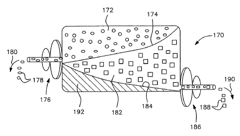
In Figure 13, bottle 170 includes a chamber 172 having a curved inclined
surface 174 leading to dispensing outlet or nozzle 176 for release of droplets
178
in the direction of arrow 180. Vertically below chamber 172 is chamber 182
having curved inclined wall 184 for guiding the contents of chamber 182 to
dispensing nozzle or outlet 186 for release of droplets 188 in the direction
of arrow
190. Vertically below the chamber 182 is fill material 192 to complete the
volume
of the bottle 170. In this embodiment, two disparate materials may be
separately
stored in a single bottle and be released from the bottle while maintaining
the
bottle in a horizontal orientation.
17
CA 02685897 2009-11-02
WO 2008/137036 PCTIUS2008/005630
Figure 14 is similar to Figure 13 except that, in Figure 14, the inclined
surface 194 of chamber 196 of bottle 198 is flat. Vertically lower chamber 200
includes inclined surface 202 as its lower wall.
Inclined surface 194 leads the contents of chamber 196 to outlet nozzle or
dispenser 204, whereas the inclined wall 2021eads the contents of chamber 200
to outlet nozzle or dispenser 206. The portion of the bottle 198 located below
chamber 200 includes fill material 208.
The foregoing description should be considered as illustrative only of the
principles of the invention. Since numerous modifications and changes will
readily occur to those skilled in the art, it is not desired to limit the
invention to the
exact construction and operation shown and described, and, accordingly, all
suitable modifications and equivalents may be resorted to, falling within the
scope
of the invention.
18