Language selection

Search

Patent 2685957 Summary

Third-party information liability

Some of the information on this Web page has been provided by external sources. The Government of Canada is not responsible for the accuracy, reliability or currency of the information supplied by external sources. Users wishing to rely upon this information should consult directly with the source of the information. Content provided by external sources is not subject to official languages, privacy and accessibility requirements.

Claims and Abstract availability

Any discrepancies in the text and image of the Claims and Abstract are due to differing posting times. Text of the Claims and Abstract are posted:

  • At the time the application is open to public inspection;
  • At the time of issue of the patent (grant).
(12) Patent: (11) CA 2685957
(54) English Title: ADAPTIVE SUNLIGHT REDIRECTOR
(54) French Title: DISPOSITIF ADAPTATIF DE REDIRECTION DE LA LUMIERE DU SOLEIL
Status: Deemed expired
Bibliographic Data
(51) International Patent Classification (IPC):
  • F21V 7/00 (2006.01)
  • F21S 11/00 (2006.01)
  • G02B 5/08 (2006.01)
  • G02B 5/12 (2006.01)
(72) Inventors :
  • SCOTT, JON DAVID EDWARD (Canada)
  • WHITEHEAD, LORNE A. (Canada)
(73) Owners :
  • THE UNIVERSITY OF BRITISH COLUMBIA (Canada)
(71) Applicants :
  • THE UNIVERSITY OF BRITISH COLUMBIA (Canada)
(74) Agent: OYEN WIGGS GREEN & MUTALA LLP
(74) Associate agent:
(45) Issued: 2012-02-21
(86) PCT Filing Date: 2008-06-16
(87) Open to Public Inspection: 2008-12-31
Examination requested: 2009-11-02
Availability of licence: N/A
(25) Language of filing: English

Patent Cooperation Treaty (PCT): Yes
(86) PCT Filing Number: PCT/CA2008/001144
(87) International Publication Number: WO2009/000070
(85) National Entry: 2009-11-02

(30) Application Priority Data:
Application No. Country/Territory Date
60/945,653 United States of America 2007-06-22

Abstracts

English Abstract

Longitudinally adjacent plane mirrors (106~114) are pivotally interconnected in a columnar array (56) by non-stretching linkages (120) which constrain movement of the mirrors such that their normal vectors (115) remain parallel. Pivotable couplings (122, 124) in two mirrors permit movement of the mirrors with respect to mutually perpendicular axes (x, y) and prevent movement of the mirrors with respect to a third axis (z). Two actuators (117A, 117B) coupled to one of the pivotable couplings controllably move a selected mirror with respect to the mutually perpendicular axes (x, y). A first frame (116) couples the mirror columns together so that movement of the selected mirror moves all the mirrors in unison. The actuators controllably move the mirrors to orient the normal vectors such that the mirrors specularly reflect incident light in a preselected direction.


French Abstract

Des miroirs plats longitudinalement adjacents (106~114) sont reliés en colonnes (56) par pivotement à l'aide de liaisons non extensibles (120) qui limitent le mouvement des miroirs afin que leurs vecteurs normaux (115) restent parallèles. Des accouplements pivotants (122, 124) dans deux miroirs permettent un mouvement des miroirs par rapport à des axes mutuellement perpendiculaires (x, y) et empêchent tout mouvement des miroirs par rapport à un troisième axe (z). Deux actionneurs (117A, 117B) couplés à l'un des accouplements pivotants déplacent de manière contrôlable un miroir sélectionné par rapport aux axes mutuellement perpendiculaires (x, y). Un premier cadre (116) couple les colonnes de miroirs les unes aux autres afin que le mouvement du miroir sélectionné déplace tous les miroirs à l'unisson. Les actionneurs déplacent les miroirs de manière contrôlable afin d'orienter les vecteurs normaux afin que les miroirs reflètent de manière spéculaire la lumière incidente dans une direction présélectionnée.

Claims

Note: Claims are shown in the official language in which they were submitted.


-10-

WHAT IS CLAIMED IS:


1. A sunlight redirector, comprising:
an array (56) of plane mirrors, each mirror having a sur-
face normal vector (115);
non-stretching linkages (120) pivotally interconnecting
longitudinally adjacent ones (106-114) of the mirrors and con-
straining movement of the mirrors such that the normal vectors
remain parallel while the mirrors move;
a first pivotable coupling (122) in a first one (106) of the
longitudinally adjacent mirrors; and
a second pivotable coupling (124) in a second one (114) of
the longitudinally adjacent mirrors;
the first and second pivotable couplings permitting the first and
second mirrors to move with respect to either one of two mutu-
ally perpendicular axes (x, y) and preventing movement of the
first and second mirrors with respect to a third axis (z).


2. A sunlight redirector as defined in claim 1, wherein:
the mirrors are arranged in a plurality of columns
(94-104); and
the non-stretching linkages connect each mirror to an
adjacent mirror in the same column.


3. A sunlight redirector as defined in claim 1, wherein:
the first and second pivotable couplings are first and second
universal joints (122, 124) each having a first member (126)
rotatable with respect to a first one (x) of the two mutually per-
pendicular axes, and a second member (128) rotatable with
respect to a second one (y) of the two mutually perpendicular
axes;


-11-


the first mirror (106) surrounds and pivots on the first
member (126) of the first universal joint; and
the second mirror (114) surrounds and pivots on the first
member (126) of the second universal joint.


4. A sunlight redirector as defined in claim 1, further comprising:
a first electronically controllable actuator (1 17A) coupled to
one of the pivotable couplings to controllably move a selected one
of the mirrors with respect to a first one (x) of the two mutually
perpendicular axes; and
a second electronically controllable actuator (117B) coupled
to the one of the pivotable couplings to controllably move the
selected one of the mirrors with respect to a second one (y) of the
two mutually perpendicular axes;
and wherein:
a light ray incident (68) on one side of the array is reflected
once by one of the mirrors through an opposite side of the array;
and
the actuators are controllable to move the mirrors to orient
the normal vectors such that the mirrors specularly reflect inci-
dent light in a preselected direction.


5. A sunlight redirector as defined in claim 1, further comprising:
a first electronically controllable actuator (117A) coupled to
one of the pivotable couplings to controllably move a selected one
of the mirrors with respect to a first one (x) of the two mutually
perpendicular axes; and
a second electronically controllable actuator (117B) coupled
to the one of the pivotable couplings to controllably move the
selected one of the mirrors with respect to a second one (z) of the
two mutually perpendicular axes.


-12-

6. A sunlight redirector as defined in claim 1, operative as a helio-
stat.


7. A sunlight redirector as defined in claim 2, wherein the third axis
(z) is perpendicular to the two mutually perpendicular axes (x, y)
and parallel to a direction of longitudinal extent of the columns.


8. A sunlight redirector as defined in claim 5, wherein:
the first and second pivotable couplings are first and second
universal joints (122, 124) each having a first member (126)
rotatable with respect to a first one (x) of the two mutually per-
pendicular axes, and a second member (128) rotatable with
respect to a second one (y) of the two mutually perpendicular
axes;
the first mirror (106) surrounds and pivots on the first
member (126) of the first universal joint; and
the second mirror (114) surrounds and pivots on the first
member (126) of the second universal joint.


9. A sunlight redirector as defined in claim 2, operative as a helio-
stat.


10. A sunlight redirector as defined in claim 4, operative as a helio-
stat.


11. A sunlight redirector as defined in claim 2, further comprising:
a first electronically controllable actuator (117A) coupled to
one of the pivotable couplings to controllably move a selected one
of the mirrors with respect to a first one (x) of the two mutually
perpendicular axes; and


-13-


a second electronically controllable actuator (117B) coupled
to the one of the pivotable couplings to controllably move the
selected one of the mirrors with respect to a second one (y) of the
two mutually perpendicular axes;
and wherein:
a light ray (68) incident on one side of the array is reflected
once by one of the mirrors through an opposite side of the array;
and
the actuators are controllable to move the mirrors to orient
the normal vectors such that the mirrors specularly reflect inci-
dent light in a preselected direction.


12. A sunlight redirector as defined in claim 2, further comprising:
a first frame (116) pivotally coupled to one mirror in each
one of the columns;
in each one of the columns:
a first pivot link (130) coupled between a second
frame (132) and one pivotable coupling in one mirror; and
a second pivot link (130) coupled between the second
frame and another pivotable coupling in another mirror;
wherein a mirror in any column coupled to the first frame has the
same columnar position as a mirror in any other column coupled
to the first frame.


13. A sunlight redirector as defined in claim 5, operative as a helio-
stat.


14. A sunlight redirector as defined in claim 2, operative as a helio-
stat and wherein:
the first and second pivotable couplings are first and second
universal joints (122, 124) each having a first member (126)


-14-

rotatable with respect to a first one (x) of the two mutually per-
pendicular axes, and a second member (128) rotatable with
respect to a second one (y) of the two mutually perpendicular
axes;
the first mirror (106) surrounds and pivots on the first
member (126) of the first universal joint; and
the second mirror (114) surrounds and pivots on the first
member (126) of the second universal joint.


15. A sunlight redirector as defined in claim 8, operative as a helio-
stat.


16. A sunlight redirector as defined in claim 13, wherein:
the mirrors are arranged in a plurality of columns; and
the non-stretching linkages connect each mirror to an
adjacent mirror in the same column.


17. A sunlight redirector as defined in claim 11, further comprising:
a first frame (116) pivotally coupled to one mirror in each
column;
in each one of the columns:
a first pivot link (130) coupled between a second
frame (132) and one pivotable coupling in one mirror; and
a second pivot link (130) coupled between the second
frame and another pivotable coupling in another mirror.

18. A sunlight redirector as defined in claim 15, wherein:
a light ray (68) incident on one side of the array is reflected
once by one of the mirrors through an opposite side of the array;
and


-15-


the actuators are controllable to move the mirrors to orient
the normal vectors such that the mirrors specularly reflect inci-
dent light in a preselected direction.


19. A sunlight redirector as defined in claim 16, wherein:
the first and second pivotable couplings are first and second
universal joints (122, 124) each having a first member (126)
rotatable with respect to a first one (x) of the two mutually per-
pendicular axes, and a second member (128) rotatable with
respect to a second one (y) of the two mutually perpendicular
axes;
the first mirror (106) surrounds and pivots on the first
member (126) of the first universal joint; and
the second mirror (114) surrounds and pivots on the first
member (126) of the second universal joint.


20. A sunlight redirector as defined in claim 17, operative as a helio-
stat.


21. A sunlight redirector operative as a heliostat, the sunlight
redirector comprising:
an array (56) of plane mirrors, each mirror having a sur-
face normal vector (115);
non-stretching linkages (120) pivotally interconnecting
longitudinally adjacent ones (106-114) of the mirrors and con-
straining movement of the mirrors;
a first pivotable coupling (122) in a first one (106) of the
longitudinally adjacent mirrors; and
a second pivotable coupling (124) in a second one (114) of
the longitudinally adjacent mirrors;


-16-

the first and second pivotable couplings permitting the first
and second mirrors to move with respect to either one of two
mutually perpendicular axes (x, y) and preventing movement of
the first and second mirrors with respect to a third axis (z);
wherein:
the mirrors are arranged in a plurality of columns
(94-104); and
the non-stretching linkages connect each mirror to an
adjacent mirror in the same column.


22. A sunlight redirector as defined in claim 21, wherein:
the first and second pivotable couplings are first and second
universal joints (122, 124) each having a first member (126)
rotatable with respect to a first one (x) of the two mutually per-
pendicular axes, and a second member (128) rotatable with
respect to a second one (y) of the two mutually perpendicular
axes;
the first mirror (106) surrounds and pivots on the first
member (126) of the first universal joint;
the second mirror (114) surrounds and pivots on the first
member (126) of the second universal joint; and
the mirrors are movable to orient the normal vectors such
that the mirrors specularly reflect incident light in directions
which deviate from a preselected normal direction by an amount
large enough to produce a preselected pattern in the reflected
light, and small enough to prevent interference between adjacent
mirrors when the mirrors are moved.


23. A sunlight redirector as defined in claim 22, wherein:


-17-

a light ray (68) incident on one side of the array is reflected
once by one of the mirrors through an opposite side of the array;
and
the mirrors are movable to orient the normal vectors such
that the normal vectors of the mirrors are oriented to specularly
reflect incident light in a preselected direction.


24. A sunlight redirector as defined in claim 21, further comprising:
a first frame (116) pivotally coupled to one mirror in each
column; and
in each one of the columns:
a first pivot link (130) coupled between a second
frame (132) and one pivotable coupling in one mirror; and
a second pivot link (130) coupled between the second
frame and another pivotable coupling in another mirror;
wherein the mirrors are movable to orient the normal vectors
such that the mirrors specularly reflect incident light in directions
which deviate from a preselected normal direction by an amount
large enough to produce a preselected pattern in the reflected
light, and small enough to prevent interference between adjacent
mirrors when the mirrors are moved.


25. A sunlight redirector as defined in claim 24, wherein:
the first and second pivotable couplings are first and second
universal joints (122, 124) each having a first member (126)
rotatable with respect to a first one (x) of the two mutually per-
pendicular axes, and a second member (128) rotatable with
respect to a second one (y) of the two mutually perpendicular
axes;
the first mirror (106) surrounds and pivots on the first
member (126) of the first universal joint; and


-18-

the second mirror (114) surrounds and pivots on the first
member (126) of the second universal joint.


26. A sunlight redirector as defined in claim 24, wherein:
a light ray incident on one side of the array is reflected
once by one of the mirrors through an opposite side of the array;
and
the mirrors are movable to orient the normal vectors such
that the normal vectors of the mirrors are oriented to specularly
reflect incident light in a preselected direction.


27. A sunlight redirector operative as a heliostat, the sunlight
redirector comprising:
an array (56) of plane mirrors, each mirror having a sur-
face normal vector (115);
non-stretching linkages (120) pivotally interconnecting
longitudinally adjacent ones (106-114) of the mirrors and con-
straining movement of the mirrors;
a first pivotable coupling (122) in a first one (106) of the
longitudinally adjacent mirrors;
a second pivotable coupling (124) in a second one (114) of
the longitudinally adjacent mirrors;
the first and second pivotable couplings permitting the first
and second mirrors to move with respect to either one of two
mutually perpendicular axes (x, y) and preventing movement of
the first and second mirrors with respect to a third axis (z);
a first electronically controllable actuator (117A) coupled to
one of the pivotable couplings to controllably move a selected one
of the mirrors with respect to a first one (x) of the two mutually
perpendicular axes; and


-19-

a second electronically controllable actuator (117B) coupled
to the one of the pivotable couplings to controllably move the
selected one of the mirrors with respect to a second one (y) of the
two mutually perpendicular axes;
wherein:
the mirrors are arranged in a plurality of columns
(94-104); and
the non-stretching linkages connect each mirror to an
adjacent mirror in the same column.

28. A sunlight redirector as defined in claim 27, wherein:
the first and second pivotable couplings are first and second
universal joints (122, 124) each having a first member (126)
rotatable with respect to a first one (x) of the two mutually per-
pendicular axes, and a second member (128) rotatable with
respect to a second one (y) of the two mutually perpendicular
axes;
the first mirror (106) surrounds and pivots on the first
member (126) of the first universal joint;
the second mirror (114) surrounds and pivots on the first
member (126) of the second universal joint; and
the mirrors are movable to orient the normal vectors such
that the mirrors specularly reflect incident light in directions
which deviate from a preselected normal direction by an amount
large enough to produce a preselected pattern in the reflected
light, and small enough to prevent interference between adjacent
mirrors when the mirrors are moved.

29. A sunlight redirector as defined in claim 28, wherein:


-20-

a light ray (68) incident on one side of the array is reflected
once by one of the mirrors through an opposite side of the array;
and
the actuators are controllable to move the mirrors such that
the normal vectors of the mirrors are oriented to specularly
reflect incident light in a preselected direction.

30. A sunlight redirector as defined in claim 27, further comprising:
a first frame (116) pivotally coupled to one mirror in each
column; and
in each one of the columns:
a first pivot link (130) coupled between a second
frame (132) and one pivotable coupling in one mirror; and
a second pivot link (130) coupled between the second
frame and another pivotable coupling in another mirror;
wherein the mirrors are movable to orient the normal vectors
such that the mirrors specularly reflect incident light in directions
which deviate from a preselected normal direction by an amount
large enough to produce a preselected pattern in the reflected
light, and small enough to prevent interference between adjacent
mirrors when the mirrors are moved.

31. A sunlight redirector as defined in claim 30, wherein:
the first and second pivotable couplings are first and second
universal joints (122, 124) each having a first member (126)
rotatable with respect to a first one (x) of the two mutually per-
pendicular axes, and a second member (128) rotatable with
respect to a second one (y) of the two mutually perpendicular
axes;
the first mirror (106) surrounds and pivots on the first
member (126) of the first universal joint; and


-21-

the second mirror (114) surrounds and pivots on the first
member (126) of the second universal joint.

32. A sunlight redirector as defined in claim 30, wherein:
a light ray incident on one side of the array is reflected
once by one of the mirrors through an opposite side of the array;
and
the actuators are controllable to move the mirrors such that
the normal vectors of the mirrors are oriented to specularly
reflect incident light in a preselected direction.

Description

Note: Descriptions are shown in the official language in which they were submitted.


CA 02685957 2009-11-02
WO 2009/000070 PCT/CA2008/001144

ADAPTIVE SUNLIGHT REDIRECTOR
Reference to Related Application
[0001] This application claims the benefit of United States provi-
sional patent application serial no. 60/945,653 filed 22 June 2007.
Technical Field
[0002] This disclosure concerns redirection of sunlight into a
specific direction, regardless of the sun's position in the sky.
Back round
[0003] Building core daylight illumination systems would facilitate
illumination of the core regions of a building with sunlight, thus reduc-
ing electrical lighting requirements and improving lighting quality.
Widespread usage of building core daylight illumination systems in the
most common workplace environment-substantially open-plan, multi-
storey office buildings-could significantly reduce energy consumption
and greenhouse gas emissions. To foster their widespread usage,
building core daylight illumination systems must be cost-effective. A
cost-effective sunlight redirector for a building core daylight illumina-
tion system is disclosed below.

Brief Description of Drawings
[0004] Figure 1 A is schematic, fragmented, side elevation view of
a 3-storey portion of a building having prior art solar canopies mounted
above the building's windows along a south facade of the building.
[0005] Figure 1 B is a partially fragmented schematic top plan view
of one of the Figure 1A solar canopies, showing the optical component
configuration.
[0006] Figure 2A is a front elevation schematic depiction of six
columns of pivotally interconnected mirrors, depicting the mirrors in a
neutral (non-rotated) position.


CA 02685957 2009-11-02
WO 2009/000070 PCT/CA2008/001144
-2-
[0007] Figure 2B is similar to Figure 2A, except the mirrors are
depicted in an azimuth-rotated position.
[0008] Figure 2C is similar to Figures 2A and 2B, except the
mirrors are depicted in an altitude-rotated position.
[0009] Figure 3A is a top front oblique isometric illustration of a
mirror and a universal joint.
[0010] Figure 3B is a top plan illustration of a mirror and univer-
sal joint like those of Figure 3A, but with the universal joint shown
schematically and showing two actuators coupled to the universal joint.
[0011] Figure 4A is a schematic top plan view of a 6-column
portion of a columnar mirror array, with solid lines depicting the
mirrors' neutral positions and dashed lines depicting rotation of the
mirrors about the depicted y-axis.
[0012] Figure 4B is similar to Figure 4A, except the dashed lines
depict rotation of the mirrors about the depicted x-axis.
[0013] Figure 4C is similar to Figures 4A and 4B, except the
dashed lines depict rotation of the mirrors about both of the depicted x
and y axes.
[0014] Figure 4D is similar to Figures 4A, 4B and 4C, except the
dashed lines depict undesirable rotation of the mirrors about a z axis
which is perpendicular to both of the depicted x and y axes.
Description
[0015] Throughout the following description, specific details are
set forth in order to provide a more thorough understanding of the
disclosure. In some instances, well known elements have not been
shown or described in detail to avoid unnecessarily obscuring the
disclosure. Accordingly, the specification and drawings are to be
regarded in an illustrative, rather than a restrictive, sense.
[0016] Figure 1A schematically depicts a 3-storey portion of a
building 10 with prior art solar canopies 12, 14, 16 mounted along a


CA 02685957 2009-11-02
WO 2009/000070 PCT/CA2008/001144
-3-
south facade of building 10 above windows 18, 20, 22 respectively.
Each one of solar canopies 12, 14, 16 captures sunlight and redirects
the sunlight through a corresponding one of weather-protected openings
24, 26, 28 in the exterior wall of building 10, and into a corresponding
one of sunlight distributors (i.e. light guides) 30, 32, 34. Plenum
spaces 36, 38, 40 are conventionally provided for each floor of building
10, i.e. plenum space 36 is provided between the first floor's ceiling 42
and drop ceiling 44, plenum space 38 is provided between the second
floor's ceiling 46 and drop ceiling 48, and plenum space 40 is provided
between the third floor's ceiling 50 and drop ceiling 52. Sunlight
distributors 30, 32, 34 are provided within plenum spaces 36, 38, 40
respectively to distribute sunlight within building 10. Alternatively,
instead of being invisibly recessed within a drop ceiling, the sunlight
distributors could be incorporated in an exposed ceiling design similar
to those in which ventilation ducts, etc. remain visible.
[0017] Figure 1 B schematically depicts an exemplary one of solar
canopies 12, 14, 16; namely solar canopy 12 which houses optical and
mechanical components within transparent cover 54. Cover 54 protects
the components from wind, precipitation, dirt, etc., facilitates formation
of the components from relatively inexpensive and lightweight materi-
als, and reduces the components' maintenance requirements. Only
sunlight-receiving portions of solar canopy 12 need be transparent;
other portions thereof (e.g. side portions which never face the sun) may
be opaque. The optical components housed within solar canopy 12
include sunlight redirecting mirror arrays 56, 58 and paraboloidal
mirrors 60, 62, 64, 66. Mirror arrays 56, 58 reflect incident sunlight
rays 68 toward paraboloidal mirrors 60, 62 respectively as indicated by
dashed lines 70, 72 and 74, 76 respectively. Paraboloidal mirrors 60,
62 redirect the reflected rays toward paraboloidal mirrors 64, 66 re-
spectively as indicated by dashed lines 78, 80 and 82, 84 respectively.
Paraboloidal mirrors 64, 66 further redirect the reflected rays through


CA 02685957 2009-11-02
WO 2009/000070 PCT/CA2008/001144
-4-
wall opening 24 into sunlight distributor 30 as indicated by dashed lines
86, 88 and 90, 92 respectively. Paraboloidal mirrors 60, 62, 64, 66 are
configured and oriented with respect to mirror arrays 56, 58 such that
light rays are redirected into sunlight distributor 30 at an appropriate
range of angles for transmission by sunlight distributor 30. This disclo-
sure pertains to sunlight redirecting mirror arrays 56, 58; not to
paraboloidal mirrors 60, 62, 64, 66 or sunlight distributor 30.
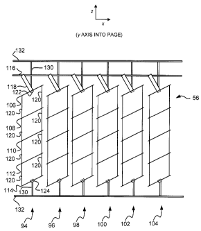
[0018] Figures 2A-2C schematically depict an exemplary one of
mirror arrays 56, 58; namely mirror array 56, which has six columns
94, 96, 98, 100, 102, 104 of mirrors. Each column has five thin,
rectangular, planar mirrors. For example, column 94 has five mirrors
106, 108, 110, 112, 114, etc. Each mirror has a notional surface
normal vector 115 (Figures 3A and 3B). Mirror columns 94, 96, 98,
100, 102, 104 are pivotally connected to rigid rectangular first frame
116. Specifically, the uppermost mirror in each column (i.e. mirror
106 in column 94, etc.) is pivotally connected to first frame 116 by a
pair of brackets, only one of which (i.e. bracket 118 in column 94, etc.)
is visible in Figures 2A and 2B. Neither the brackets nor first frame
116 are shown in Figure 2C to avoid obscuring other details. First
frame 116 couples the columns of mirrors together so that all of the
mirrors in array 56 move in unison.
[0019] The mirrors in each column are mechanically coupled
together such that they can easily be rotated in two planes in order to
adjust the mirrors' positions as the altitude and azimuth of the sun
changes, without allowing the mirrors to interfere with (i.e. contact)
one another as they move. The mirrors should not excessively shade
one another as they move, although some minimal shading during
relatively brief positions of the mirrors, the sun, or both, is acceptable
to optimize overall efficiency of the sunlight redirector.
[0020] Each intermediate mirror in each column (i.e. mirrors 108,
110, 112 in column 94, etc.) is pivotally connected to the mirrors


CA 02685957 2009-11-02
WO 2009/000070 PCT/CA2008/001144
-5-
immediately above and below the intermediate mirror by linkages 120.
Linkages 120 need not be rigid members, although they may be.
Linkages 120 may be formed of a non-stretching material such as
stainless steel wire. The opposed ends of each linkage 120 can be
connected to the mirrors by ball joints, flexible elastomeric connectors,
or other suitable means which permits the mirrors to pivot easily about
the points at which linkages 120 are connected to the mirrors. If
linkages 120 are not rigid, they should be held under sufficient tension
(e.g. by adjusting the length of each linkage 120) that they behave as
rigid members.
[0021] A universal joint (i.e. pivotable coupling) is provided in the
center of the top and the bottom mirror in each column (i.e. universal
joints 122, 124 are provided in mirrors 106, 114 respectively of column
94, etc.). Provision of two such universal joints per column allows the
mirrors in each column to rotate about the depicted x and y axes which
are perpendicular to the direction of longitudinal extent of the column,
while preventing the mirrors from rotating about the z axis which is
parallel to the direction of longitudinal extent of the column and perpen-
dicular to the x and y axes.
[0022] Figures 3A and 3B show mirror 106 and universal joint
122 in greater detail. Universal joint 122 incorporates an x-axis rota-
tional member 126 and a y-axis rotational member 128. One end of
pivot link 130 is fixed to x-axis rotational member 126. The opposite
end of pivot link 130 is fixed to an external second frame 132 (Figures
2A-2C) which is separate from and is not connected to first frame 116.
As seen in Figures 2A-2C, one pivot link 130 extends upwardly from
top mirror 106's universal joint 122 to an upper portion of second frame
132, and another pivot link 130 extends downwardly from bottom
mirror 114's universal joint 124 to a lower portion of second frame
132, thereby securely bracing mirror column 94 to prevent rotation of
the column 94 mirrors about the z axis. Although the universal joints


CA 02685957 2009-11-02
WO 2009/000070 PCT/CA2008/001144
6-
are relatively inexpensive, they increase cost somewhat so it is desirable
to provide them in only the top and bottom mirrors of each column.
This is facilitated by linkages 120, which are less expensive than the
universal joints, to facilitate pivotable movement of the intermediate
mirrors.
[0023] First frame 116 may be coupled to any one of the mirrors
in a column, provided the frame-coupled mirror in any column has the
same columnar position relative to the frame-coupled mirrors in the
other columns. For example, first frame 116 can be coupled, by the
aforementioned brackets, to the top mirror in each column, or to the
second mirror in each column, or to the bottom mirror in each column,
etc. If the mirrors are interconnected as aforesaid, two inexpensive
electronically controllable electro-mechanical rotational actuators
(117A, 117B) can be used to smoothly move all of the mirrors in array
56 in unison, with very little torque. The two actuators can be provided
on any one of the mirrors in which a universal joint is provided, as
shown in Figure 3B. Well known algorithms can be used to apply
suitable control signals to the actuators, to cause predetermined angular
displacement of the x and y-axis rotational members 126, 128 of the
universal joint in the mirror on which the actuators are provided.
Specifically, the actuators can be adaptively controlled to move the
mirrors to track the sun, thereby continually redirecting sunlight into a
specific direction (i.e. toward paraboloidal mirrors 60, 62, 64, 66 and
thence into sunlight distributor 30), regardless of the sun's posi-
tion-provided the sun is located within a predetermined angular range
corresponding to about 3 hours of true local solar noon (i.e. a signifi-
cant part of a typical work day). Each sunlight redirecting mirror array
56, 58 is accordingly operative as a heliostat.
[0024] The solid lines in Figures 2A and 4A-4D show the mir-
rors in the neutral (non-rotated) position. Figure 2B, and the dashed
lines in Figure 4A show the mirrors in an azimuth-rotated position, i.e.


CA 02685957 2009-11-02
WO 2009/000070 PCT/CA2008/001144
-7-
after suitable controlled operation of the actuators to rotate the mirrors
about the depicted y-axis. Figure 2C, and the dashed lines in Figure 4B
show the mirrors in an altitude-rotated position, i.e. after suitable
controlled operation of the actuators to rotate the mirrors about the
depicted x-axis. The dashed lines in Figure 4C show the mirrors in an
azimuth and altitude-rotated position, i.e. after suitable controlled
operation of the actuators to rotate the mirrors about both of the de-
picted x and y axes. The dashed lines in Figure 4D show how the
mirrors would undesirably interfere with one another if they were not
constrained, by the universal joints, to prevent them from rotating about
the z axis (i.e. the axis which is perpendicular to both of the depicted x
and y axes).
[0025] In operation, a light ray incident 68 on one side of one of
mirror arrays 56, 58 is reflected once by one of the mirrors in that
array and passes through to the opposite side of the array, as indicated
by dashed lines 70, 72 and 74, 76 respectively in Figure 1B. The
actuators are controllably actuated to move the mirrors such that the
mirrors' normal vectors are oriented, according to the law of specular
reflection, such that incident light 68 is reflected into a preselected
reflection direction.
[0026] Each mirror may be approximately 17 x 19 cm, although
other sizes are acceptable. If the mirrors are too large, solar canopy 12
will extend too far off the side of building 10, which is architecturally
undesirable. If the mirrors are too small, the cost of mirror array 56
may be excessive, which is also undesirable. The mirrors in each
column should be spaced apart from one another such that the maxi-
mum amount of sunlight is captured, while minimizing shading of one
mirror by the mirror above it. An array having six columns of seven
mirrors per column, with each mirror approximately 17 x 19 cm in
size, and with the mirrors in each column spaced about 12 cm apart,
produces acceptable results. A 3 metre canopy (measured in the x


CA 02685957 2009-11-02
WO 2009/000070 PCT/CA2008/001144
-8-
direction shown in 1 B) may house two such mirror arrays, as shown in
Figure 1 B.
[0027] While a number of exemplary aspects and embodiments
have been discussed above, those of skill in the art will recognize
certain modifications, permutations, additions and sub-combinations
thereof. It is therefore intended that the following appended claims and
claims hereafter introduced are interpreted to include all such modifica-
tions, permutations, additions and sub-combinations as are within their
true spirit and scope.
[0028] For example, the actuators can be provided in an analogous
mechanical arrangement coupled to first frame 116 and positioned
adjacent mirror array 56.
[0029] The columnar mirrors within mirror arrays 56, 58 need not
be vertically adjacent or vertically aligned with one another as shown in
Figures 2A-2C. For example, the mirrors could be connected together
in diagonally extending columns or other longitudinally extending
columns. However linkages 120 should not be pivotally connected to
the mirrors so as to permit the linkages to extend parallel to the planes
of the mirrors for any position within the mirrors' intended angular
operational range. For example, if the neutral position of the mirrors is
horizontal, then the mirrors should not be connected in horizontal rows.
[0030] As another example, if the mirrors within mirror arrays 56,
58 are perfectly parallel to one another they will reflect sunlight as
aforesaid, but they will not concentrate the sunlight-only paraboloidal
mirrors 60, 62, 64, 66 will concentrate the sunlight. It is however
possible to configure mirror arrays 56, 58 to contribute to concentration
of the sunlight. This can be achieved by maintaining the plane of each
mirror at a slight angle relative to the planes of the other mirrors,
instead of maintaining the mirrors parallel to one another. More
particularly, the actuators can be controlled to move the mirrors such
that the orientation of each mirror's normal vector deviates slightly


CA 02685957 2009-11-02
WO 2009/000070 PCT/CA2008/001144
-9-
from that of the other mirrors. Consequently, according to the law of
reflection, incident light 68 is reflected into directions which deviate
slightly from a preselected reflection direction. The deviation of each
mirror's normal vector should be large enough to produce a preselected
pattern in the reflected light. Appropriate selection of the deviation of
each mirror's normal vector facilitates some concentration (i.e. focus-
ing) of the sunlight as it is redirected toward paraboloidal mirrors 60,
62, 64, 66. This reduces the degree of sunlight concentration required
of paraboloidal mirrors 60, 62, 64, 66 thereby reducing the optical
quality-and hence cost-of paraboloidal mirrors 60, 62, 64, 66.
[0031] The deviation of each mirror's normal vector should
however be limited, since if the deviation is too great adjacent mirrors
may interfere with (i.e. contact or excessively shade) one another as
they are moved to track the sun, particularly at extreme azimuth or
altitude angles. This can be alleviated by increasing the spacing be-
tween adjacent mirrors and columns of mirrors, but at the expense of
reduced efficiency since some light would pass through the increased
spacing between adjacent mirrors without being reflected by the mirrors
and hence be lost in the sense that such light would not be distributed
within building 10.

Representative Drawing
A single figure which represents the drawing illustrating the invention.
Administrative Status

For a clearer understanding of the status of the application/patent presented on this page, the site Disclaimer , as well as the definitions for Patent , Administrative Status , Maintenance Fee  and Payment History  should be consulted.

Administrative Status

Title Date
Forecasted Issue Date 2012-02-21
(86) PCT Filing Date 2008-06-16
(87) PCT Publication Date 2008-12-31
(85) National Entry 2009-11-02
Examination Requested 2009-11-02
(45) Issued 2012-02-21
Deemed Expired 2020-08-31

Abandonment History

There is no abandonment history.

Payment History

Fee Type Anniversary Year Due Date Amount Paid Paid Date
Request for Examination $200.00 2009-11-02
Registration of a document - section 124 $100.00 2009-11-02
Application Fee $400.00 2009-11-02
Maintenance Fee - Application - New Act 2 2010-06-16 $100.00 2009-11-02
Maintenance Fee - Application - New Act 3 2011-06-16 $100.00 2011-04-08
Final Fee $300.00 2011-12-07
Maintenance Fee - Patent - New Act 4 2012-06-18 $100.00 2012-05-17
Maintenance Fee - Patent - New Act 5 2013-06-17 $200.00 2013-03-19
Maintenance Fee - Patent - New Act 6 2014-06-16 $200.00 2014-05-22
Maintenance Fee - Patent - New Act 7 2015-06-16 $200.00 2015-06-16
Maintenance Fee - Patent - New Act 8 2016-06-16 $400.00 2017-06-01
Maintenance Fee - Patent - New Act 9 2017-06-16 $400.00 2018-06-11
Maintenance Fee - Patent - New Act 10 2018-06-18 $250.00 2018-06-11
Owners on Record

Note: Records showing the ownership history in alphabetical order.

Current Owners on Record
THE UNIVERSITY OF BRITISH COLUMBIA
Past Owners on Record
SCOTT, JON DAVID EDWARD
WHITEHEAD, LORNE A.
Past Owners that do not appear in the "Owners on Record" listing will appear in other documentation within the application.
Documents

To view selected files, please enter reCAPTCHA code :


To view images, click a link in the Document Description column. To download the documents, select one or more checkboxes in the first column and then click the "Download Selected in PDF format (Zip Archive)" or the "Download Selected as Single PDF" button.

List of published and non-published patent-specific documents on the CPD .

If you have any difficulty accessing content, you can call the Client Service Centre at 1-866-997-1936 or send them an e-mail at CIPO Client Service Centre.


Document
Description 
Date
(yyyy-mm-dd) 
Number of pages   Size of Image (KB) 
Abstract 2009-11-02 2 75
Representative Drawing 2009-11-02 1 19
Description 2009-11-02 9 468
Drawings 2009-11-02 7 126
Claims 2009-11-02 12 438
Cover Page 2010-01-06 2 48
Representative Drawing 2012-01-24 1 11
Cover Page 2012-01-24 2 50
Maintenance Fee Payment 2017-06-01 1 34
PCT 2009-11-02 2 66
Assignment 2009-11-02 12 493
Prosecution-Amendment 2009-11-02 1 47
Correspondence 2009-12-23 1 27
PCT 2010-01-15 1 36
Correspondence 2010-11-05 1 32
Correspondence 2010-11-29 1 28
Correspondence 2011-05-05 2 135
Correspondence 2011-12-07 1 33