Note: Descriptions are shown in the official language in which they were submitted.
CA 02686400 2010-04-19
1
DISTANCE DETERMINATION
FROM A MAGNETICALLY PATTERNED TARGET WELL
FIELD OF THE INVENTION
The present invention relates generally to drilling and surveying subterranean
boreholes such as for use in oil and natural gas exploration. In particular,
this invention
relates to methods for determining a distance between a twin well and a
magnetized target
well.
CA 02686400 2010-04-19
2
BACKGROUND OF THE INVENTION
The use of magnetic field measurements in prior art subterranean surveying
techniques for determining the direction of the earth's magnetic field at a
particular point
is well known. Techniques are also well known for using magnetic field
measurements to
locate subterranean magnetic structures, such as a nearby cased borehole.
These
techniques are often used, for example, in well twinning applications in which
one well
(the twin well) is drilled in close proximity and often substantially parallel
to another well
(commonly referred to as a target well).
The magnetic techniques used to sense a target well may generally be divided
into two main groups; (i) active ranging and (ii) passive ranging. In active
ranging, the
local subterranean environment is provided with an external magnetic field,
for example,
via a strong electromagnetic source in the target well. The properties of the
external field
are assumed to vary in a known manner with distance and direction from the
source and
thus in some applications may be used to determine the location of the target
well. In
contrast to active ranging, passive ranging techniques utilize a preexisting
magnetic field
emanating from magnetized components within the target borehole. In
particular,
conventional passive ranging techniques generally take advantage of
magnetization
present in the target well casing string. Such magnetization is typically
residual in the
casing string because of magnetic particle inspection techniques that are
commonly
utilized to inspect the threaded ends of individual casing tubulars.
In co-pending, commonly assigned, U.S. Patent No. 7,656,161 (U.S. Patent
Application Serial No. 11/301,762) to McElhinney, a technique is disclosed in
which a
predetermined magnetic pattern is deliberately imparted to a plurality of
casing tubulars.
These tubulars, thus magnetized, are coupled together and lowered into a
target well to
CA 02686400 2010-04-19
3
form a magnetized section of casing string typically including a plurality of
longitudinally
spaced pairs of opposing magnetic poles. Passive ranging measurements of the
magnetic
field may then be advantageously utilized to survey and guide drilling of a
twin well
relative to the target well. For example, the distance between the twin and
target wells
may be determined from magnetic field strength measurements made in the twin
well.
This well twinning technique may be used, for example, in steam assisted
gravity
drainage (SAGD) applications in which horizontal twin wells are drilled to
recover heavy
oil from tar sands.
While the above described method of magnetizing wellbore tubulars has been
successfully utilized in well twinning applications, there is room for yet
further
improvement. For example, it has been found that the above described
longitudinal
magnetization method can result in a somewhat non-uniform magnetic flux
density along
the length of a casing string at distances of less than about 6-8 meters. If
unaccounted,
the non-uniform flux density can result in distance errors on the order of
about 1 meter
when the distance between the two wells is about 5-6 meters. While such
distance errors
are typically within specification for most well twinning operations, it would
be desirable
to improve the accuracy of distance calculations between the target and twin
wells.
Moreover, passive ranging surveys are typically acquired at about 10 meter
intervals along the length of the twin well. More closely spaced distance
measurements
may sometimes be advantageous (or even required) to accurately place the twin
well. For
example, more frequent distance measurements would be advantageous during an
approach (also referred to in the art as a landing) or during a period of
unusual drift in
either the target or twin well. Taking more frequent magnetic surveys is
undesirable
CA 02686400 2010-04-19
4
since each magnetic survey requires a stoppage in drilling (and is therefore
costly in
time).
Therefore, there exists a need for improved methods for determining the
distance between a twin well and a magnetically patterned target well. In
particular, there
is a need for a method that accounts for fluctuations in magnetic field
strength and
thereby improves the accuracy of the determined distances. There is also a
need for a
dynamic distance measurement method (i.e., a method for determining the
distance
between that does not require a stoppage in drilling).
CA 02686400 2009-10-30
WO 2008/137064 PCT/US2008/005671
SUMMARY OF THE INVENTION
Exemplary aspects of the present invention are intended to address the above
described need for improved methods for determining the distance between a
twin well
and a magnetized target well. In one exemplary embodiment, the invention
includes
5 processing the strength of the interference magnetic field and a variation
in the field
strength along the longitudinal axis of the target well to determine the
distance to the
target well. In another exemplary embodiment of the invention, measurement of
the
component of the magnetic field vector aligned with the tool axis may be
acquired while
drilling and utilized to determine the distance between the two wells in
substantially real
time. Still other exemplary embodiments of the invention enable both the
distance
between the twin and target wells and the axial position of the magnetic
sensors relative
to the target well to be determined. In one of these exemplary embodiments the
magnitude and direction of the interference magnetic field vector are
processed to
determine the distance and the axial position. In another of these exemplary
embodiments, the change in direction of the interference magnetic field vector
between
first and second longitudinally spaced magnetic field measurements may be
processed to
determine the distance and axial position.
Exemplary embodiments of the present invention provide several advantages
over prior art well twinning and distance determination methods. For example,
exemplary embodiments of this invention improve the accuracy of distance
calculations
between twin and target wells. Such improvements in accuracy enable a drilling
operator
to position a twin well with increased accuracy relative to the target well.
Moreover,
exemplary embodiments of the invention also enable the distance between the
twin and
target wells to be determined in substantially real time. These real-time
distances may be
CA 02686400 2009-10-30
WO 2008/137064 PCT/US2008/005671
6
used, for example, to make real-time steering decisions. Moreover, exemplary
embodiments of this invention also enable the axial position of the magnetic
sensors
relative to the target well to be determined.
In one aspect, the present invention includes a method for determining the
distance between a twin well and a target well, the target well being
magnetized such that
it includes a substantially periodic pattern of opposing north-north (NN)
magnetic poles
and opposing south-south (SS) magnetic poles spaced apart along a longitudinal
axis
thereof. The method includes deploying a drill string in the twin well, the
drill string
including a magnetic sensor in sensory range of magnetic flux emanating from
the target
well and measuring a magnetic field with the magnetic sensor. The method
further
includes processing the measured magnetic field to determine a magnitude of an
interference magnetic field attributable to the target well and processing the
magnitude of
the interference magnetic field to determine a first distance to the target
well. The
method also includes estimating an axial position of the magnetic sensor
relative to at
least one of the opposing magnetic poles imparted to the target well and
processing the
first distance in combination with the estimated axial position to determine a
second
distance to the target well.
.In another aspect, this invention includes a method for estimating the
distance
between a twin well and a magnetized target well in substantially real time
during drilling
of the twin well. The target well is magnetized such that it includes a
substantially
periodic pattern of opposing north-north (NN) magnetic poles and opposing
south-south
(SS) magnetic poles spaced apart along a longitudinal axis thereof. The method
includes
deploying a drill string in the twin well, the drill string including a
magnetic sensor in
sensory range of magnetic flux emanating from the target well and measuring an
axial
CA 02686400 2009-10-30
WO 2008/137064 PCT/US2008/005671
7
component of the magnetic flux in substantially real time during drilling, the
axial
component substantially parallel with a longitudinal axis of the twin well.
The method
further includes processing the measured axial component to estimate a
magnitude of an
interference magnetic field vector attributable to the target well and
processing the
estimated magnitude of the interference magnetic field vector to estimate the
distance
between the twin and target wells.
In still another aspect, this invention includes a method for determining a
distance between a twin well and a target well, the target well being
magnetized such that
it includes a substantially periodic pattern of opposing north-north (NN)
magnetic poles
and opposing south-south (SS) magnetic poles spaced apart along a longitudinal
axis
thereof. The method includes deploying a drill string in the twin well, the
drill string
including a magnetic sensor in sensory range of magnetic flux emanating from
the target
well and measuring a magnetic field with the magnetic sensor. The method
further
includes processing the measured magnetic field to determine first and second
components of an interference magnetic field vector attributable to the target
well, the
first and second components being selected from the group consisting of (i) a
magnitude
of the interference magnetic field vector and an angle of the interference
magnetic field
vector with respect to a fixed reference and (ii) magnitudes of first and
second orthogonal
components of the interference magnetic field vector. The method also includes
processing the first and second components of the interference magnetic field
vector in
combination with a model relating the first and second components to (i) the
distance and
(ii) an axial position of the magnetic field sensor relative to the target
well to determine
the distance between the magnetic field sensor and the target well.
CA 02686400 2009-10-30
WO 2008/137064 PCT/US2008/005671
8
In yet another aspect this invention includes a method for determining a
distance
between a twin well and a target well, the target well being magnetized such
that it
includes a substantially periodic pattern of opposing north-north (NN)
magnetic poles and
opposing south-south (SS) magnetic poles spaced apart along a longitudinal
axis thereof.
The method includes deploying a drill string in the twin well, the drill
string including a
magnetic sensor in sensory range of magnetic flux emanating from the target
well and
measuring a magnetic field at first and second longitudinally spaced locations
in the
borehole. The method further includes processing the first and second magnetic
field
measurements to determine first and second directions of an interference
magnetic field
vector at the corresponding first and second locations and processing the
first and second
directions and a difference in measured depth between the first and second
locations with
a model relating a direction of the interference magnetic field vector to the
distance
between the twin well and the target well to determine the distance.
The foregoing has outlined rather broadly the features and technical
advantages
of the present invention in order that the detailed description of the
invention that follows
may be better understood. Additional features and advantages of the invention
will be
described hereinafter which form the subject of the claims of the invention.
It should be
appreciated by those skilled in the art that the conception and the specific
embodiments
disclosed may be readily utilized as a basis for modifying or designing other
structures for
carrying out the same purposes of the present invention. It should also be
realize by those
skilled in the art that such equivalent constructions do not depart from the
spirit and scope
of the invention as set forth in the appended claims.
CA 02686400 2009-10-30
WO 2008/137064 PCT/US2008/005671
9
BRIEF DESCRIPTION OF THE DRAWINGS
For a more complete understanding of the present invention, and the advantages
thereof, reference is now made to the following descriptions taken in
conjunction with the
accompanying drawings, in which:
FIGURE 1 depicts a prior art arrangement for a SAGD well twinning operation.
FIGURE 2 depicts a prior art magnetization of a wellbore tubular.
FIGURE 3 depicts a plot of distance versus measured depth for a surface test.
FIGURE 4 depicts a plot of magnetic field strength versus measured depth for
the surface
test of FIGURE 3.
FIGURE 5 depicts a plot of the axial component of the magnetic field as a
function of
measured depth for a well twinning operation.
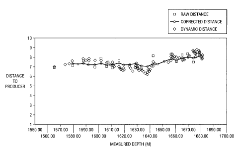
FIGURE 6 depicts a plot of distance versus measured depth for the well
twinning
operation shown on FIGURE 5.
FIGURE 7A depicts a dual contour plot of the magnitude M and direction of the
interference magnetic field vector as a function of normalized distance d and
axial
position 1 along the target well.
FIGURE 7B depicts a dual contour plot of the magnitude of the components of
the
interference magnetic field vector perpendicular to and parallel with the
target well as a
function of normalized distance away from the target well (on the y-axis), and
axial
position along the target well (on the x-axis).
CA 02686400 2010-04-19
DETAILED DESCRIPTION
FIGURE 1 schematically depicts one exemplary embodiment of a well twinning
application such as a SAGD twinning operation. Typical SAGD twinning
operations
require a horizontal twin well 20 to be drilled a substantially fixed distance
substantially
directly above a horizontal portion of the target well 30 (e.g., not deviating
more than
about 1-2 meters up or down or to the left or right of the lower well). In the
exemplary
embodiment shown, the lower (target) borehole 30 is drilled first, for
example, using
conventional directional drilling and MWD techniques. However, the invention
is not
limited in this regard. The target borehole 30 is then cased using a plurality
of
premagnetized tubulars (such as those shown on FIGURE 2 described below). As
described in co-pending, commonly assigned U.S. Patent No. 7,656,161 (U.S.
Patent
Application Serial No. 11/301,762), measurements of the magnetic field about
the target
well 30 may then be used to guide subsequent drilling of the twin well 20. In
the
embodiment shown, drill string 24 includes at least one tri-axial magnetic
field
measurement sensor 28 deployed in close proximity to the drill bit 22. Sensor
28 is used
to passively measure the magnetic field about target well 30 as the twin well
is drilled.
Such passive magnetic field measurements are then utilized to guide continued
drilling of
the twin well 20 along a predetermined path relative to the target well 30.
For example,
as described in the `762 Application, the distance between the twin 20 and
target 30 wells
may be determined (and therefore controlled) via such magnetic field
measurements.
With reference now to FIGURE 2, one exemplary tubular 60 magnetized as
described in the `762 Application is shown. The exemplary tubular 60
embodiment
shown includes a plurality of discrete magnetized zones 62 (typically three or
more).
Each magnetized zone 62 may be thought of as a discrete cylindrical magnet
having a
CA 02686400 2010-04-19
11
north N pole on one longitudinal end thereof and a south S pole on an opposing
longitudinal end thereof such that a longitudinal magnetic flux 68 is imparted
to the
tubular 60. Tubular 60 further includes a single pair of opposing north-north
NN poles 65
at the midpoint thereof. The purpose of the opposing magnetic poles 65 is to
focus
magnetic flux outward from tubular 60 as shown at 70 (or inward for opposing
south-
south poles as shown at 72).
It will be appreciated that the present invention is not limited to the
exemplary
embodiments shown on FIGURES 1 and 2. For example, the invention is not
limited to
SAGD applications. Rather, exemplary methods in accordance with this invention
may
be utilized to drill twin wells having substantially any relative orientation
for substantially
any application. For example, embodiments of this invention may be utilized
for river
crossing applications (such as for underwater cable runs). Moreover, the
invention is not
limited to any particular magnetization pattern or spacing of pairs of
opposing magnetic
poles on the target well. The invention may be utilized for target wells
having a
longitudinal magnetization (e.g., as shown on FIGURE 2) and/or a transverse
magnetization.
With continued reference to FIGURE 1, exemplary embodiments of sensor 28 are
shown to include three mutually orthogonal magnetic field sensors, one of
which is
oriented substantially parallel with the borehole axis (Mz). Sensor 28 may
thus be
considered as determining a plane (defined by Mx and My) orthogonal to the
borehole axis
and a pole (Mz) parallel to the borehole axis of the twin well, where Mx, My,
and Mz
CA 02686400 2009-10-30
WO 2008/137064 PCT/US2008/005671
12
represent measured magnetic field vectors in the x, y, and z directions. As
described in
more detail below, exemplary embodiments of this invention may only require
magnetic
field measurements along the longitudinal axis of the drill string 24 (Mz as
shown on
FIGURE 1).
The magnetic field about the magnetized casing string may be measured and
represented, for example, as a vector whose orientation depends on the
location of the
measurement point within the magnetic field. In order to determine the
magnetic field
vector due to the target well (e.g., target well 30) at any point downhole,
the magnetic
field of the earth is typically subtracted from the measured magnetic field
vector,
although the invention is not limited in this regard. The magnetic field of
the earth
(including both magnitude and direction components) is typically known, for
example,
from previous geological survey data or a geomagnetic model. However, for some
applications it may be advantageous to measure the magnetic field in real time
on site at a
location substantially free from magnetic interference, e.g., at the surface
of the well or in
a previously drilled well. Measurement of the magnetic field in real time is
generally
advantageous in that it accounts for time dependent variations in the earth's
magnetic
field, e.g., as caused by solar winds. However, at certain sites, such as an
offshore
drilling rig, measurement of the earth's magnetic field in real time may not
be practical.
In such instances, it may be preferable to utilize previous geological survey
data in
combination with suitable interpolation and/or mathematical modeling (i.e.,
computer
modeling) routines.
The earth's magnetic field at the tool and in the coordinate system of the
tool may
be expressed, for example, as follows:
MEX = H,: (cos D sin Az cos R + cos D cos Az cos Inc sin R - sin D sin Inc sin
R)
CA 02686400 2009-10-30
WO 2008/137064 PCT/US2008/005671
13
MEY = HE (cos D cos Az cos Inc cos R + sin D sin Inc cos R - cos D sin Az sin
R)
MEZ = HE (sin D cos Inc - cos D cos Az sin Inc) Equation 1
where MEx, MEY, and MEZ represent the x, y, and z components, respectively, of
the
earth's magnetic field as measured at the downhole tool, where the z component
is
aligned with the borehole axis, HE is known (or measured as described above)
and
represents the magnitude of the earth's magnetic field, and D, which is also
known (or
measured), represents the local magnetic dip. Inc, Az, and R represent the
Inclination,
Azimuth (relative to magnetic north) and Rotation (also known as the gravity
tool face),
respectively, of the tool, which may be obtained, for example, from
conventional
surveying techniques. However, as described above, magnetic azimuth
determination can
be unreliable in the presence of magnetic interference. In such applications,
where the
measured borehole and the target borehole are essentially parallel (i.e.,
within five or ten
degrees of being parallel), Az values from the target well, as determined, for
example in a
historical survey, may be utilized.
The magnetic field vectors due to the target well (also referred to as
interference
vectors in the art) may then be represented as follows:
MTx = Mx - MEX
MTY =MY - MEY
M77 = MZ - MEZ Equation 2
where MTx, Mry, and MTZ represent the x, y, and z components, respectively, of
the
interference magnetic field vector due to the target well and Mx, My, and Mz,
as described
above, represent the measured magnetic field vectors in the x, y, and z
directions,
respectively.
CA 02686400 2009-10-30
WO 2008/137064 PCT/US2008/005671
14
The artisan of ordinary skill will readily recognize that in determining
magnetic
field vectors about the target well it may also be necessary to subtract other
magnetic
field components from the measured magnetic field vectors. For example, such
other
magnetic field components may be the result of drill string, steering tool,
and/or drilling
motor interference. Techniques for accounting for such interference are well
known in
the art. Moreover, magnetic interference may emanate from other nearby cased
boreholes. In SAGD applications in which multiple sets of twin wells are
drilled in close
proximity, it may be advantageous to incorporate the magnetic fields of the
various
nearby wells into a mathematical model.
The magnetic field strength due to the target well may be represented, for
example,
as follows:
M = VM,X + M,1., +M1 Z Equation 3
where M represents the magnetic field strength due to the target well (also
referred
to herein as the interference magnetic field strength) and MTx, MTY, and MTZ
are defined
above with respect to Equation 2. The magnetic field strength, M, is sometimes
also
referred to equivalently in the art as the total magnetic field (TMF) and/or
the magnetic
flux density. As disclosed in the `762 Patent Application, the measured
magnetic field
strength, M, may be utilized to determine the distance between twin and target
wells. For
example, the magnetic field strength, M, was disclosed to decrease with
increasing
distance.
CA 02686400 2009-10-30
WO 2008/137064 PCT/US2008/005671
IMPROVED DISTANCE CALCULATION
With reference now to FIGURE 3, actual and calculated distances are plotted as
a
function of measured depth for a surface test. The calculated distances were
determined
5 from an empirically based falloff equation assuming an exponential decrease
in the
magnetic field strength, M, with increasing distance. Measurements were made
at
distances ranging from 3 to 7 meters. FIGURE 3 shows an approximately periodic
variation in the calculated distance as a function of measured depth (along
the
longitudinal axis of the target). The calculated distances shown on FIGURE 3,
are all
10 within about 15% of the actual distances. This is within the specifications
for typical well
twinning applications (such as SAGD applications). Notwithstanding, it would
be
advantageous to improve the accuracy of the calculated distances and in
particular true
move the above described periodic variations.
The above-described variation in the calculated distance is due to an
approximately
15 periodic variation in the magnetic field strength along the axis of the
target well. It has
been observed that the magnetic field strength is greater at locations
adjacent pairs of
opposing magnetic poles than at locations between the pairs of opposing poles
(resulting
in smaller calculated distances adjacent the pairs of opposing poles than
between adjacent
pairs). As described above, the calculated distances shown on FIGURE 3 are
determined
via an empirically based logarithmic falloff equation. An equation of the
following form
has been found to work well with both slotted and non-slotted tubulars
commonly used in
SAGD operations:
d, = a ln(M) + b Equation 4
CA 02686400 2009-10-30
WO 2008/137064 PCT/US2008/005671
16
where d1 represents the distance between the two wells, M represents the
magnetic
field strength (e.g., as determined in Equation 3), and a and b represent
empirical fitting
parameters.
With reference to FIGURE 4, magnetic field strength is plotted as a function
of
measured depth for the surface test described above with respect to FIGURE 3.
As
shown, the magnetic field strength is approximately periodic with measured
depth, with
the amplitude of the variation decreasing significantly with increasing
distance to the
target well. The amplitude of the variation as a function of distance may be
described
mathematically, for example, via a fourth order polynomial equation of the
following
form:
A = sd, 4 + td,' + ud, 2 + vd, + w Equation 5
where A represents the amplitude of the variation of the magnetic field along
the
longitudinal axis, d1 represents the distance between the measurement point
and the target
well, and s, t, u, v, and w represent empirically derived fitting parameters.
In one exemplary embodiment of the present invention, the distance between
twin
and target wells may be calculated with improved accuracy if the axial
position of the
sensors 28 (FIGURE 1) with respect to the target well (in particular with
respect to the
pairs of opposing magnetic poles) is known. The axial position of the sensors
may be
determined, for example, by monitoring the variation of various components,
such as the
axial component Mz. In a preferred embodiment Mz (or Mme) is measured in real
time
during drilling and telemetered (e.g., via mud pulse telemetry) to the surface
at some
suitable interval (e.g., one or two data points per minute). The axial
position of sensor 28
(FIGURE 1) along the target well may be determined from these substantially
real-time
magnetic field measurements in any number of suitable ways. The individual
CA 02686400 2009-10-30
WO 2008/137064 PCT/US2008/005671
17
components of the interference magnetic field vector (e.g., Mme) are periodic
along the
axis of the target well due to the periodic nature of the casing string
magnetization (i.e.,
due to the repeating pairs of opposing magnetic poles). In the exemplary
embodiment
shown on FIGURE 2, the period (the distance between adjacent opposing NN
poles) is
equal to the length of a single casing tubular (although the invention is not
limited to any
particular period length). MTz is maximum and minimum at axial positions
between
adjacent pairs of opposing poles and approximately zero at positions adjacent
pole pairs
(NN and SS pole pairs).
In accordance with one exemplary embodiment of the present invention, the
distance between twin and target wells may be determined as follows:
1. Determine the interference magnetic field strength.
2. Estimate the distance between the twin and target wells from the
interference magnetic field strength, for example, via Equation 4.
3. Estimate the amplitude of the variation of the interference magnetic field
strength along the longitudinal axis at the distance estimated in step 2, for
example, using Equation 5.
4. Determine the axial position of the magnetic field sensor deployed in the
twin well with respect to the pairs of opposing magnetic poles imparted to
the target well, for example, using substantially real time measurements of
the axial component of the magnetic field as described above.
5. Determine the local amplitude of the magnetic field variation along the
axis
(the amplitude of the variation at the axial position determined in step 4),
for example, according to an equation of the form: AM = A sin 0 , where
AM represents the local amplitude, A represents the amplitude determined
CA 02686400 2009-10-30
WO 2008/137064 PCT/US2008/005671
18
in step 3, and 9 represents the axial position of the sensors with respect to
the target (e.g., as a phase angle where 0=0 degrees represents a NN
opposing pole and 0=180 degrees represents a SS opposing pole).
6. Correct the measured interference magnetic field strength to remove the
local amplitude determined in step 5, for example, as follows:
M2 =M - OM , where M2 represents the corrected interference magnetic
field strength.
7. Recalculate the distance to the target well using the corrected
interference
magnetic field strength from step 6, for example, using Equation 4 as
follows: d2 = a ln(M2 / Mo) , where d2 represents the corrected distance.
In step 5, the variation of the magnetic field strength along the axis is
assumed to
be sinusoidal. It will be appreciated that the invention is not limited to any
particular
periodic function. Other suitable periodic functions (e.g., a triangular wave
function) may
also be utilized.
ESTIMATION OF DISTANCE IN SUBSTANTIALLY REAL TIME
Substantially real-time measurements of the axial component of the magnetic
field
Mz (or of the interference magnetic field vector, Mme) may also be utilized to
provide a
substantially real-time estimate of the distance between the twin and target
wells during
drilling (i.e., stoppage not required). For example, the interference magnetic
field
strength, M, may be estimated graphically as shown on FIGURE 5, which plots
the axial
component of the magnetic field MZ versus measured depth for SAGD well
twinning
operation.. The interference magnetic field strength, M, is approximately
equal to half of
CA 02686400 2009-10-30
WO 2008/137064 PCT/US2008/005671
19
the peak'to trough amplitude Mz. It will be appreciated that M may be
substituted into
Equation 4 to obtain a substantially real time estimate of the distance
between the two
wells. With respect to FIGURE 5B, note that the distance to the target well is
increasing
with increasing measured depth as indicated by the decreasing peak to trough
amplitude
with increasing measured depth, thereby indicating a of the direction of
drilling of the
twin well relative to the target well. The artisan of ordinary skill in the
art will readily
recognize that the axial component of the interference magnetic field vector,
MTZ, may
also be utilized. In applications in which the direction of drilling is
substantially constant
(straight ahead), Mz and Mrr may be equivalently utilized. In applications in
which the
drilling direction is changing (curved), the use of M7-z is preferred as the
earth's magnetic
field component (which changes with the changing borehole direction) has been
removed
(e.g., according to Equation 2).
The interference magnetic field strength, M, may also be estimated
mathematically
from the axial component of the interference magnetic field vector, Mme, and
the axial
position of the magnetic sensor, for example, as follows:
M = M'Z Equation 6
sin 0
where 0 represents the axial position of the sensors with respect to the
target well,
with 0=0 degrees representing a NN opposing pole and 0=180 degrees
representing a SS
opposing pole. In Equation 6, the periodic variation of M7-Z along the axis of
the target
well is assumed to be approximately sinusoidal. It will be appreciated that
the invention
is not limited in this regard and that other periodic functions may be
utilized. The
distance to the target well may then be estimated, for example, by
substituting M
(estimated via FIGURE 5 or Equation 6) into Equation 4. The magnetic field
strength
CA 02686400 2009-10-30
WO 2008/137064 PCT/US2008/005671
estimated in FIGURE 5 or Equation 6 may also be in step 1 of the method
described
above.
With reference now to FIGURE 6, the distance between twin and target wells is
plotted as a function of measured depth for the same SAGD operation shown on
FIGURE
5 5. The distance is determined using three different methods. First the "raw"
distance is
determined from the interference magnetic field strength according to Equation
4. This
method is similar to the method disclosed by McElhinney in the '762 Patent
Application.
Second, a "corrected" distance is determined using the exemplary method
embodiment
described above in steps 1 through 7. And third, a "dynamic" distance is
determined
10 using the substantially real time Mrr measurements described above. Note
that the
"corrected" distance has reduced noise as compared to the prior art "raw"
distance clearly
showing the increasing distance between the two wells beginning at a measured
depth of
about 1640 meters. The "dynamic" distance also provides a surprisingly
accurate
measurement of the distance and is expected to be suitable for controlling the
distance
15 between the two wells for most twinning applications. In fact the accuracy
of the
"dynamic" method may be sufficient to increase the spacing between static
survey
stations (or possibly even to obviate the need for static survey measurements
in certain
applications), thereby reducing drilling time and the costs of a well twinning
operation.
It will thus be understood that the invention is not limited to embodiments in
which
20 the earth's magnetic field is removed from the measured magnetic field
(e.g., as described
above in Equations 1 and 2). For example, the earth's magnetic field has not
been
removed from FIGURE 5 (note that the approximately periodic variation in
magnetic
field strength is not centered at zero). Notwithstanding, as described above,
FIGURE 5
may still be utilized to determine a distance to the target well. Likewise,
the artisan of
CA 02686400 2009-10-30
WO 2008/137064 PCT/US2008/005671
21
ordinary skill in the art would be readily able to incorporate the earth's
magnetic field
into the mathematical models describe above and below such that removal of the
earth's
magnetic field from the measured magnetic field is not necessary.
DISTANCE AND AXIAL POSITION DETERMINATION
In the previously described exemplary embodiments of this invention, the
measured magnetic field strength of the interference magnetic field vector and
the axial
position of the magnetic field sensors (in the twin well) relative to the
target well are
utilized to determine the distance between the twin and target wells. In an
alternative
embodiment of this invention, the magnetic field vector may be utilized to
uniquely
determine both the distance between the two wells and the axial position of
the magnetic
field sensor relative to the opposing magnetic poles imparted to the target
well (referred
to as a normalized axial position).
The artisan of ordinary skill in the art will readily recognize that any
vector may be
analogously defined by either (i) the magnitudes of first and second in-plane,
orthogonal
components of the vector or by (ii) a magnitude and a direction (angle)
relative to some
in-plane reference. Likewise, the interference magnetic field vector may be
defined by
either (i) the magnitudes of first and second in-plane, orthogonal components
or by (ii) a
magnitude and a direction (angle). In the exemplary embodiments shown below,
the first
and second in-plane, orthogonal components of the interference magnetic field
vector are
referred to as parallel and perpendicular components (being correspondingly
parallel with
and perpendicular to the target well). The perpendicular component is defined
as being
positive when it points away from the target well while the parallel component
is defined
as being positive when it points in the direction of increasing measured
depth.
CA 02686400 2010-04-19
22
Equivalently, when the magnitude and direction of the interference magnetic
field are
utilized, an angle of 0 degrees corresponds with the perpendicular component
and
therefore indicates a direction pointing orthogonally outward from the target.
An angle of
90 degrees corresponds with the parallel component and therefore indicates a
direction
pointing parallel to the target well in the direction of increasing measured
depth. The
invention is, of course, not limited by such arbitrary conventions.
As described above (as well as in commonly assigned, co-pending U.S. Patent
No.
7,656,161 (U.S. Patent Application Serial No. 11/301,762), the pattern of
opposing
magnetic poles imparted to the target casing string results in a measurable
magnetic flux
about the casing string. Moreover, as stated above, the interference magnetic
field vector
is uniquely related to the distance between the twin and target wells and the
axial position
of the magnetic field sensors relative to the opposing poles imparted to the
target well.
This may be expressed mathematically, for example, as follows:
MN =f,(d,1)
MP = f2 (d, l) Equation 7
where MN and MP define the interference magnetic field vector and represent
the magnitude of the components perpendicular (normal) to and parallel with
the target
well, d represents the distance between the two wells, 1 represents the
normalized axial
position of the magnetic field sensors along the axis of the target well, and
f, (=) and
f2 (=) represent first and second mathematical functions (or empirical
correlations) that
define MN and MP with respect to d and 1. In one exemplary embodiment in which
the
twin and target wells are substantially parallel, the magnitudes MN and MP may
be
CA 02686400 2009-10-30
WO 2008/137064 PCT/US2008/005671
23
determined from the x, y, and z components of the interference magnetic field
vector, for
example, as follows:
z z
MN = M,.X + Mr,,
MP = I M7Z I Equation 8
where Mn,, , Mn, , and M7Z are as defined above, for example, with respect to
Equation 2. The signs (positive or negative) of MN and MP may be determined as
discussed hereinabove from the direction of the interference magnetic field
relative to the
target well. In the more general case (where the twin and target wells are not
parallel),
the artisan of ordinary skill would readily be able to derive similar
relationships.
The mathematical functions/correlations f, (=) and f2 (=) (in Equation 7) may
be
determined using substantially any suitable techniques. For example, in one
exemplary
embodiment of this invention, bi-axial magnetic field measurements are made at
a two-
dimensional matrix (grid) of known orthogonal distances d and normalized axial
positions
l relative to a string of magnetized tubulars deployed at a surface location.
MN and Mp
may then be determined from the bi-axial measurements (e.g., the first axis
may be
perpendicular to the target thereby indicating MN and the second axis may be
parallel with
the target thereby indicating Mp). It will be understood that MN and Mp may
also be
determined from tri-axial magnetic field measurements, e.g., via Equation 8.
Known
interpolation and extrapolation techniques can then be used to determine MN
and MP at
substantially any location relative to the target well (thereby empirically
defining f, ( )
and f2 (=) ). In another exemplary embodiment of this invention, f, (=) and f2
(=) may be
determined via a mathematical model (e.g., a finite element model) of a semi-
infinite
CA 02686400 2009-10-30
WO 2008/137064 PCT/US2008/005671
24
string of magnetized wellbore tubulars. Such a model may include, for example,
pairs of
opposing magnetic poles of known strength and spacing along the string.
One such dipole mathematical model is shown on FIGURE 7A, which is a dual
contour plot of MN (solid lines) and MP (dashed lines) plotted as a function
of distance
from (y-axis) and along (x-axis) the casing string. The distances are
normalized to the
axial spacing between adjacent NN pole pairs (which in one exemplary
embodiment is
twice the length of a casing joint - approximately 24 meters). A normalized
distance of
0.0 (on the x-axis) represents an axial position adjacent a NN pair of
opposing poles and a
normalized distance of 0.5 represents an axial position adjacent a SS pair of
opposing
poles.
Upon measuring MN and MP (the orthogonal and parallel components of the
interference magnetic field vector), d and 1 may be determined using
substantially any
suitable techniques. For example, d and 1 may be determined graphically from
FIGURE
7A using known graphical solution techniques. Alternatively, d and 1 may be
determined
mathematically, for example, via mathematically inverting Equation 7 so that:
d= 3(MN,MP)
l = f4 (MN , MP) Equation 9
where d, 1, MN, and MP are as defined above and f3 (=) and f4 (=) represent
mathematical functions that define d and 1 with respect to MN and M. It will
be
appreciated that substantially any known mathematical inversion techniques,
including
known analytical and numerical techniques, may be utilized. Equation 9 is
typically
(although not necessarily) solved for d and 1 using known numerical
techniques, e.g.,
sequential one-dimensional solvers. The invention is not limited in these
regards.
CA 02686400 2009-10-30
WO 2008/137064 PCT/US2008/005671
It will be appreciated that the interference magnetic field vector (as
represented by
MN and Mp in FIGURE 7A) repeats at normalized distance intervals of 1.0 along
the axis
of the target well. It will thus be understood that the axial position 1
determined above
does not uniquely determine the absolute measured depth of the twin well with
respect to
5 the target well. Rather the axial position 1 defines the location of the
magnetic field
sensor within a single period (i.e. a normalized distance of 1.0) along the
axis of the target
well. As such, the axial position 1 is typically referenced with respect to
the nearest NN
or SS opposing poles. There is no such periodicity in the distance d
determined via the
various exemplary embodiments of the present invention.
10 As stated above, the interference magnetic field vector may be equivalently
defined
by the magnitude and direction (e.g., the angle with respect to the target
well) of the
vector. Thus, Equation 7 may be rewritten, for example, as follows:
M = f,'(d,1)
cp = f2 (d, 1) Equation 10
15 where M and (p define the interference magnetic field vector and represent
the
magnitude (interference magnetic field strength) and direction (the angle
relative to the
target well) of the vector, d represents the distance between the two wells, 1
represents the
normalized axial position of the magnetic field sensors along the axis of the
target well,
and f,' (.) and f2 (=) represent alternative mathematical functions (or
empirical
20 correlations) that define the magnitude M and direction qp with respect to
d and 1. M and ~o
may be determined from MN and MP, for example, as follows:
M MN 2 + M,, Z
CA 02686400 2009-10-30
WO 2008/137064 PCT/US2008/005671
26
rp = arctan M" Equation 11
P
With reference now to FIGURE 7B, a dual contour plot of M (solid lines) and cp
(dashed lines) is shown as a function of normalized distances from (y-axis)
and along (x-
axis) the casing string. The dual contour plot of FIGURE 7B was generated
using the
same dipole model used to generate the contour plot shown on FIGURE 7A. As
described above, the magnitude and direction of the interference magnetic
field repeats at
a normalized distance interval of 1.0 along the axis of the target well (M
repeating at
intervals of 0.5 and (p repeating at intervals of 1.0). As also described
above, the distance
d between the twin and target wells and the axial,position 1 along the target
well may be
determined using any suitable techniques, for example graphically utilizing
FIGURE 7B
and/or mathematically using the inversion techniques described above with
respect to
Equation 9. Use of the magnitude and direction of the interference magnetic
field vector
may be preferred for some drilling operations in that it tends to be more
robust (stable)
mathematically.
DISTANCE DETERMINATION FROM THE CHANGE
IN DIRECTION OF THE INTERFERENCE MAGNETIC FIELD VECTOR
With reference again to FIGURE 7B, the distance between the twin and target
wells may also be determined from the change in direction of the interference
magnetic
field vector between first and second axially spaced magnetic field
measurements. It can
be seen on FIGURE 7B, at normalized distances greater than about 0.25 (for the
exemplary dipole model shown), that the contours in cp are non-parallel
indicating that the
change in cp resulting from a change in axial position 1 is sensitive to the
distance d
CA 02686400 2009-10-30
WO 2008/137064 PCT/US2008/005671
27
between the wells. Accordingly, changes in cp between first and second axially
spaced
magnetic field measurements may be utilized to determine the distance d
(provided that
the axial spacing between measurements is known).
To further illustrate, note that at axial positions approximately adjacent to
either the
NN or SS opposing poles (normalized distances of about 0.0, 0.5., 1.0, etc.),
~o changes
more rapidly with increasing measured depth than at axial positions between
the opposing
poles (normalized distances of 0.25, 0.75, etc.). Accordingly, assuming that
the twin well
is substantially parallel with the target well (parallel with the x-axis on
FIGURE 7B) , the
distance, d, between the twin and target wells may be determined from first
and second
longitudinally spaced measurements of the direction, cp, of the interference
magnetic field.
This may be expressed mathematically, for example, as follows:
d =fiI(cP1,(P2,AMD)
1 f, 2 (col, (P2 , AMD) Equation 12
where d represents the distance between the twin and target wells (as
described
above), 1 represents the normalized axial position of the magnetic field
sensors along the
axis of the target well (as also described above), cp, and (P2 represent the
direction of the
interference magnetic field (with respect to the target well) at the first and
second
measurement points, MAID represents the difference in measured depth between
the two
measurement points, and fl, (=) and fie (=) indicate that that d and 1 are
mathematical
functions of T,, q02 , and AMD.
The first and second magnetic field measurements (from which gyp, , (P2 , and
AMD
are determined) may be acquired either simultaneously at first and second
longitudinally
spaced magnetic field sensors (e.g., spaced at a known distance along the
drill string) or
CA 02686400 2009-10-30
WO 2008/137064 PCT/US2008/005671
28
sequentially during drilling of the twin well. The invention is not limited in
this regard.
The mathematical function/correlations f J.) and f12 (=) may be determined
empirically
or theoretically, for example, in substantially the same manner as described
above with
respect to Equation 7 for determining f1 (=) and f2(-). Equation 12 may then
be solved
via substantially any known means (e.g., graphically or numerically as also
described
above) to determined the distance d to that target well. One exemplary
embodiment of a
graphical solution is as follows: (i) a horizontal (parallel with the x-axis)
segment of
length AMD is located on FIGURE 7B such that the left most point of the
segment
(which corresponds to the first measurement point) is at an angle equal to CPI
; (ii) the
segment is moved along the y-axis (with the left most point remaining at Cpl)
until the
right most point of the segment (which corresponds to the second measurement
point) is
at an angle equal to P2 ; and (iii) the distance between the two wells is then
determined
from the location of the segment on FIGURE 7B. It will be appreciated that the
axial
positions, l1 and 12, of the first and second measurement points may also be
determined
graphically from the location of the segment of FIGURE 7B.
It will be appreciated that the method described above with respect to
Equation 12
is not limited to the use of two axially spaced magnetic field measurements.
Rather,
substantially any number of measurements may be utilized. For example, a
method
utilizing three or more measurements having known spacing may be
advantageously
utilized to reduce measurement noise and thereby increase the accuracy of the
distance
determination. Alternatively, methods utilizing a set of three or more
magnetic field
measurements may be advantageously used to relax the assumptions made in
deriving
Equation 12 and therefore to determine other parameters of interest (e.g., an
approach
CA 02686400 2009-10-30
WO 2008/137064 PCT/US2008/005671
29
angle of the twin well relative to the target well). As stated above, the
method described
above with respect to Equation 12 inherently assumes that the twin and target
wells are
substantially parallel when only two magnetic field measurements are utilized.
This is
typically a good assumption in well twinning operations (such as SAGD
operations),
since the intent of the twinning operation is to drill substantially parallel
wells at some
fixed distance from one another. The invention, however, is not limited in
this regard as
scenarios arise in which the twin well may be approaching or diverging from
the target
well (i.e., the twin is no longer parallel with the target). In such scenarios
it would
generally be advantageous to determine the angle of approach (or divergence)
between
the two wells using three or more axially spaced magnetic field measurements.
With reference again to Equation 12, it will also be appreciated that the
distance d
and the axial position 1 may be determined independent of the interference
magnetic field
strength M. Accordingly, after determining d and l (as described above) the
measured
interference magnetic field strength may then be utilized, for example, to
determine the
strength of the magnetic poles imparted to the magnetized target well. The
pole strengths
may be determined, for example, via substituting d and 1 (determined via
Equation 12)
into Equation 10. The interference magnetic field strength M then be used to
evaluate
(calibrate) the model defined by f,' (=) , which typically includes two
principle variables;
(i) the spacing between opposing magnetic poles and (ii) the strength of the
poles (which
are assumed to be equal).
Although the present invention and its advantages have been described in
detail, it
should be understood that various changes, substitutions and alternations can
be made
herein without departing from the spirit and scope of the invention as defined
by the
appended claims.