Note: Descriptions are shown in the official language in which they were submitted.
CA 02686428 2015-12-09
SNAP HOOK
FIELD OF THE INVENTION
[0005] The present invention is directed to a karabiner with at least
one hoop and
at least one closing part and at least one insertion opening of the hoop,
which can be
closed off by the closing part in a closed position, with the closing part
being pivotally
mounted at the hoop via a closing part ¨ pivot axle between the closed
position and a
maximally opened position, and with at least one blocking element being
mounted
pivotally at or in the closing part via a blocking element ¨ pivot axle, with
in at least one
blocking position the blocking element blocks the closing part in its closed
position from
any pivoting of the closing part in a direction towards its maximally opened
position and
allows in at least one released position for the closing part to pivot in the
direction
towards its maximally opened position.
BACKGROUND
[0006] Karabiners are used in the most various embodiments and for
various
purposes, e.g., in a multitude of sports, such as climbing, ice-climbing,
mountain
climbing, paragliding, hang-gliding, and the like. They are also used for
securing
working personnel from falling. In general the hoop of the karabiner is hooked
into a
rope, an eyelet, or the like. For this purpose, the rope or the eyelet is
inserted through
the insertion opening into the interior of the hoop. The insertion opening is
opened by
pivoting open the closing part. When the rope or the eyelet is inside the
hoop, the
insertion opening can be closed again by pivoting back the closing part. In
prior art
several safety measures are known intended to prevent that during use of the
karabiner
the closing part is accidentally pivoted into the open position.
1
CA 02686428 2009-11-23
[0007] A generic way of securing the closing part is known from the
first two
exemplary embodiments of WO 95/19505. In this publication, a blocking element
is
mounted inside of the pivotal closing part, pivotal around a blocking element
¨
pivot axle. This blocking element comprises a handle and a support bar. In the
blocking position, the blocking element is in such a position that the support
bar
contacts a support surface of the hoop. In this blocking position any
accidental
pivotal opening of the closing part is prevented, the closing part is
therefore
blocked from any pivoting in the direction towards its maximally opened
position.
By pressing the handle, the blocking element is pivoted. The interior support
bar
is released from any engagement with the support surface of the hoop and the
closing part can be pivoted around its closing part ¨ pivot axle in the
direction of its
maximally opened position. A return pivoting occurs via a return spring into
the
initial position when the closing part and the blocking element are released.
[0008] The disadvantage of the above-mentioned generic prior art
primarily
comprises that when operating the handle of the blocking element, this element
is
pivoted in a direction towards the support surface arranged at the hoop. This
in
turn results in the implementation of a very limited and/or small opening
angle of
the closing part. Furthermore, when operating the handle only a comparatively
short lever arm is effective, so that only a relatively weak torque is applied
upon
the closing part in the pivotal opening direction. For a pivotal opening
according to
prior art, frequently another operation is necessary directly at the closing
part.
Therefore, in practice usually the blocking element must be operated with one
finger and the closing part with another finger in order to pivot the latter
in the
direction of the maximally opened position. This is laborious and cumbersome
and
can even be dangerous, particularly when only one hand is available for
operating
the karabiner.
[0009] SUMMARY
-7-
CA 02686428 2009-11-23
[0010] The object of the invention is to provide a generic karabiner
allowing a
very large opening angle of the closing part, in which the blocking element in
its
blocking position of the closing part still securely blocks the closing part
from any
pivoting in the direction to the maximally opened position of the closing
part.
[0011] This is attained according to the invention in the blocking
element
being pivotal from the blocking position in the direction towards the released
position in the same rotary direction around the blocking element ¨ pivot axis
as
the closing part for pivoting the closing part out of the closed position in
the
direction towards its maximally opened position around the closing part ¨
pivot
axis.
[0012] According to the invention, it is therefore provided that for
releasing
the closing part, the blocking element, is pivoted in the same rotary
direction as the
closing part when it is pivoted out of its closed position in the direction
towards its
maximally opened position around the closing part ¨ pivot axis. It is
therefore
provided that the blocking element is to be pivoted out of the blocking
position in
the direction towards the released position and the closing part out of the
closed
position towards its maximally opened position, either both in the clockwise
or
accordingly both in the counter-clockwise direction. This way, it is avoided
that,
similar to prior art, when pivoting the blocking element to the maximally
possible
opening angle of the closing part it is limited by the handle of the blocking
element.
Further, when pivoting the blocking element according to the invention, a
greater
torque is applied upon the closing part than in prior art. This allows for the
blocking element and the closing part to be simultaneously operated in a
single
motion of a single finger without requiring the application of a strong force.
This
also allows a secure and simple one-handed operation.
[0013] In particular, it is provided that the blocking element
comprises a
handle for operating the blocking element and the handle for pivoting the
blocking
- 3 -
CA 02686428 2009-11-23
element out of the blocking position in the direction towards the released
position
is to be pushed or pivoted in a direction away from the closing part ¨ pivot
axis.
[0014]
In order to prevent any unintended pivoting of the blocking element
out of the blocking position right from the start it is beneficially provided
that the
closing part comprises a recess and the handle of the blocking element, and
preferably the entire blocking element, is arranged inside said recess.
Beneficially
the handle and/or the entire blocking element are located entirely inside the
recess
as indicated, which means that neither the handle nor other parts of the
blocking
element project from the exterior contours and/or the recess of the closing
part.
This preferably applies to all positions of the blocking element.
Preferred
embodiments of karabiners according to the invention provide for the blocking
element to include a contact surface contacting a support surface of the hoop.
This
support surface is beneficially arranged in an end region of the hoop, in
which
preferably the closing part ¨ pivot axle of the closing part is arranged as
well.
[0015]
Particularly beneficial embodiments provide for the blocking element
with its contact surface to roll over the support surface of the hoop when
pivoting
around the blocking element ¨ pivot axis from the blocking position towards
the
released position and/or in the opposite direction, preferably in a non-
slipping
fashion. This rolling may also be provided for only a portion of the pivotal
movement, preferably
during pivoting around the blocking element ¨ pivot axis
from the blocking position in the direction towards the released position
during the
first part of the pivotal motion. In these embodiments, the blocking element
is not
only pivoted, particularly in a non-slipping fashion, by the rolling, but it
is also
moved along the support surface of the hoop in reference thereto. In these
embodiments it is therefore not provided for the blocking element to slip or
glide
past the support surface during pivoting, but a mandatory relative motion is
achieved between the support surface and the blocking element during the
pivoting
of the blocking element.
- 4 -
CA 02686428 2009-11-23
[00 1G1 This can be used in particularly preferred embodiments in
order that
by this rolling of the contact surface at the support surface during the
pivoting of
the blocking element from the blocking position in the direction towards the
released position, the closing part is mandatorily also pivoted out of the
direction of
its closed position in the direction towards its maximally opened position.
This
consequently results in the closing part automatically being pivoted in the
direction towards its maximally opened position when the blocking element is
pivoted out of its blocking position. Therefore the operation of the blocking
element
is sufficient to automatically pivot the closing part as well. This is also
possible in
the opposite direction, of course, by mandatorily pivoting the closing part
from its
maximally opened position in the direction towards the closed position when
the
blocking element is pivoted from the released position in the direction
towards its
blocking position In these embodiments any operation of the blocking element
therefore automatically leads to a pivoting of the closing part. However,
contrary
thereto this is not provided as long as the blocking element is in its
blocking
position, because otherwise the blocking element would not fulfill its
securing
function. It is not necessary for the blocking element to prevent any pivoting
of the
closing part from a single blocking position only. Rather, it may also be
provided
that the blocking element, beginning from its first blocking position, blocks
the
closing part in its closed position against any pivoting of the closing part
in the
direction towards its maximally opened position in various blocking positions
in a
pivotal angle within a first angular range around the blocking element ¨ pivot
axle
this side of a limiting angle. When the blocking element leaves the first
angular
range it may be provided that the blocking element is mandatorily entrained in
a
second angular range beyond the limiting angle when the closing part is
pivoted in
the direction towards its maximally opened position in the direction towards a
maximally released position of the blocking element as well. In this second
angular range beyond the limiting angle it is then not necessary for the
blocking
- 5 -
CA 02686428 2009-11-23
element to mandatorily also being operated for a further pivoting of the
closing
part. The closing part may also be directly operated, with then the blocking
element also being operated in said second angular range by the pivoting of
the
closing part, by being automatically and/or mandatorily being pivoted.
In
preferred embodiments the blocking element therefore comprises several
blocking
positions not only in the first angular range at this side of the limiting
angle.
Rather, it is also provided in these embodiments that the blocking element in
the
second angular range beyond the limiting angle can accept several released
positions. In preferred variants, the limiting angle amounts to angles smaller
or
equivalent to 100, measured between a first connecting straight line between
the
blocking element ¨ pivot axis and the point of the contact surface of the
blocking
element with the greatest distance from the blocking element ¨ pivot axis and
a
second connecting straight line between the blocking element ¨ pivot axis and
the
closing part ¨ pivot axis. The reference this side of the limiting angle
comprises all
pivotal angles of the blocking element ranging between the first blocking
position
of the blocking element and the limiting angle. The reference beyond the
limiting
angle comprises all pivotal angles located on the opposite side of the
limiting angle.
The first and the second connecting straight lines each extend through the
centers
of the respective pivot axis/axes. The limiting angle is generally positioned
at the
side of the second connecting straight line pointing in the direction towards
the
first blocking position.
[0017] BRIEF DESCRIPTION OF THE DRAWINGS
[0018]
Additional features and details of a preferred exemplary embodiment
of the invention are explained in greater detail using the description of the
figures.
[0019] In the drawings:
[0020] Figs.
1 through 4 are different views of an exemplary embodiment
according to the invention, with the closing part being in the closed position
and
the blocking element in the first blocking position;
- 6 -
CA 02686428 2009-11-23
[0021] Figs. 5 and 6 are views of the same exemplary embodiment with
the
blocking element being pivoted towards the limiting angle;
[0022] Figs. 7 and 8 are views of the same exemplary embodiment again
in a
position, in which the closing part has already been pivoted by a certain
angle in
the direction towards the maximally opened position;
[0023] Figs. 9 and 10 are views of the same exemplary embodiment,
with the
closing part being in the maximally opened position according to Figs. 1
through 4;
[0024] Fig. 11 is a perspective view of the position of the closing
part
according to Figs. 1 through 4;
[0025] Fig. 12 is a perspective view in the position according to Figs. 7
and 8;
[0026] Fig. 13 is a perspective view of the karabiner in the position
according
to Figs. 9 and 10; and
[0027] Figs. 14 and 15 are views of the blocking element.
[0028] DETAILED DESCRIPTION OF THE PREFERRED EMBODIMENTS
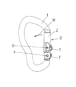
[0029] Fig. 1 shows a side view of the karabiner according to the
invention.
The closing part 2 is pivotally arranged at the hoop 1 via the closing part ¨
pivot
axle 4, in Figs. 1 through 4 the closing part 2 is in its closed position, in
which the
hoop 1 and the closing part 2 form a closed arrangement. This way, the
insertion
opening 3, through which a rope or an eyelet or the like can be inserted into
the
interior of the hoop, can be completely closed. In this side view the blocking
element ¨ pivot axle 6 is shown, around which the blocking element 5 can be
pivoted. The blocking element 5 itself is not shown, because it is arranged
entirely
inside the recess 9 in the closing part 2 and thus in the view according to
Fig. 1 it is
hidden behind the side walls of the closing part 2 limiting the recess. In
this
perspective it is therefore particularly well discernible that neither the
handle 8
nor the other parts of the blocking element 5 project from the recess 9.
[0030] Fig. 2 shows a view of the karabiner from the front. In this
view the
recess 9 is discernible in the closing part 2. The blocking element 5 as well
as the
- 7 -
CA 02686428 2009-11-23
return spring 13 are arranged therein. Fig. 2 also shows the cross-sectional
line A-
A along which the closing part 2 and the blocking element 5 are sectioned in
the
illustrations of Figs. 3 through 10. Fig. 4 shows the area B of Fig. 3
enlarged.
Here the blocking element 5, illustrated in cross-section, is particularly
well
discernible, pivotally mounted around the blocking element ¨ pivot axis 6 in
the
recess 9. It comprises the handle 9, which can be impinged e.g., with the
thumb or
another finger. Additionally, the return spring 13 is also shown, which in the
exemplary embodiment shown is provided for a reverse pivoting of the closing
part
2 into its closed position as well as the blocking element 5 into its blocking
position.
It therefore represents a single common return spring 13. In other exemplary
embodiments separate return springs for the closing part and the blocking
element
may be provided, of course. In the exemplary embodiment shown, the return
spring 13 comprises a first leg 14 and at least one second leg 15. The first
leg 14
contacts the closing part 2, and the second leg 15 contacts the blocking
element 5.
The return spring 13 contacts the blocking element ¨ pivot axle 6 in the area
between the legs 14 and 15. In the exemplary embodiment shown, it is wound in
this area around the blocking element ¨ pivot axle 6. The blocking element ¨
pivot
axle 6 is mounted in a fixed manner at the closing part 2. In the exemplary
embodiment shown, the closing part ¨ pivot axle 4 is mounted at the hoop 1 in
a
fixed manner, namely in the variant shown in the same end region 12 of the
hoop
1, in which said part also comprises the support surface 11. The blocking
element
5 contacts this support surface 11 of the hoop 1 with its contact surface 10.
In the
exemplary embodiment shown, the blocking element 5 exhibits in its cross-
section
a pin-like extension 18, with its exterior surfaces comprising the contact
surface
10, and/or at least partially forming it. In the exemplary embodiment shown
the
contact surface 10 extends from one side of the pin 18 to the opposite side of
the pin
18.
- 8 -
CA 02686428 2009-11-23
[0031] In Figs. 1 through 4, the blocking element 5 is in its first
blocking
position. With a part of its contact surface 10 it contacts an upper end
region of the
support surface 11, namely such that when it is attempted to pivot the closing
part
2 in the direction 19 towards its maximally opened position the blocking
element 5
prevents such a pivotal motion and the closing part 2 is therefore blocked in
its
closed position. The blocking effect results from the fact that when it is
attempted
to pivot the closing part 2 in the direction 19, the blocking element ¨ pivot
axle 6,
arranged in a fixed manner at the closing part 2, had to be pivoted in the
direction
19 as well, which however is prevented by the contact of the contact surface
10 of
the blocking element 5 at the support surface 11 of the hoop 1. As long as the
blocking element 5 is situated in a blocking position the closing part 2
cannot leave
its closed position. As particularly discernible in Figs. 3 through 10, the
return
spring 13 applies a force upon the blocking element 5 in all positions,
pressing the
contact surface 10 of the blocking element 5 in the direction and/or against
the
support surface 11 of the hoop 1 and/or to the support surface 11 of the hoop
1. The
support surface 11 is beneficially implemented as shown, comprising a
constantly
curved surface. This means that there are no edges, but this does not exclude
that,
as shown in the exemplary embodiment, it may have a curve radius varying over
the extension. The support surface 11 forms an exterior surface of a wedge-
shaped
projection of the hoop 1, which points with the tip of its wedge in the
direction
towards the opposite end region 20 of the hoop 1. The support surface 11 is
arranged in the area between the blocking element ¨ pivot axle 6 and the
closing
part ¨ pivot axle 4.
[0032] In order for allowing the closing part 2 to leave the closed
position
shown in Figs. 1 through 4, first the blocking element 5 must be brought into
a
released position by operating the handle 8. This occurs by pivoting the
blocking
element 5 in the rotary direction 7 around its blocking element ¨ pivot axle
6.
According to the invention, the above-mentioned rotary direction 7 represents
the
- 9 -
CA 02686428 2009-11-23
rotary direction 7, in which the closing part 2 must be pivoted around its
closing
part ¨ pivot axle 4 to be pivoted from the closed position in the direction
towards its
maximally opened position.
[0033]
Figs. 5 and 6 show cross-sectional illustrations according to Figs. 3
and 4, with the blocking element 5 however no longer being in its first
blocking
position but situated in the blocking position equivalent to the limiting
angle 16.
The first angular range of the pivotal angle of the blocking element 5 ranges
from
the positions shown in Figs. 3 and 4 and those of Fig. 5 and 6, in which the
blocking element 5 is respectively arranged in a blocking position. This means
that
in all of these positions the blocking element 5 of the closing part 2 is
still hindered
from any pivoting in the direction 19. In all these positions of the blocking
element
5 the closing part 2 may still be situated in its closed position according to
Fig. 1.
However, it is also possible, as discernible from Figs. 5 and 6, that in the
area of
the limiting angle 16 the closing part 2 is already slightly pivoted in the
direction
19, with beneficially the closing part 2 in the end region 20 still overlaps
the loop.
In this first angular range and/or in the blocking positions a force develops
attempting to pivot the closing part 2 in the direction 19, i.e. in the
direction of its
maximally opened position, by pressing the contact surface 10 to the support
surface 11, either creates a torque upon the blocking element, which acts in
the
direction of the first blocking position or a torque upon the blocking element
5 in
the opposite direction thereto, i.e. in the direction of the released
position, which is
weaker than the friction created by the compression of the contact surface 10
against the support surface 11. This way, the desired blocking effect of the
blocking element 5 is created.
[0034]
Fig. 6 shows enlarged the area, marked with a circle in Fig. 5, in order
to use it for explaining the position of the limiting angle 16. The point
(and/or the
line and/or the partial area) of the contact surface 10 with the greatest
distance 24
from the blocking element ¨ pivot axle 6 and/or its center is marked with the
- 10-
CA 02686428 2015-12-09
,
reference character 10a. The first connecting straight line 22 extends through
said point
10a and the blocking element ¨ pivot axle 6 and/or its center. The second
connecting
straight 23 extends between the blocking element ¨ pivot axle 6 and/or its
center and
the locking element ¨ blocking axle 4 and/or its center. The distance between
the
centers of the blocking element ¨ pivot axle 6 and the locking element ¨ pivot
axle 4 is
marked with the reference character 25. The limiting angle 16 is measured
between the
first connecting straight line 22 and the second connecting straight line 23.
In the
exemplary embodiment shown it amounts to approx. 8 and generally ranges
beneficially from 0 to 100 (inclusive). The first angular range at this side
of the limiting
angle 16 ranges from the first blocking position to the first connecting
straight line 22
and is marked by the arrow 26. In this angular range 26 the blocking element 5
is
always in its blocking position. The second angular range beyond the limiting
angle 16
is located on the opposite side of the first connecting straight line 22 and
is marked by
the arrow 27. In this second angular range the blocking element 5 is in its
released
position. The limiting angle 16 is generally positioned on the side of the
second
connecting straight line 23, which points in the direction 26 towards the
first blocking
position.
[0035] Without considering any play between the axial bolt of
the blocking
element ¨ pivot axis 6 and the closing part ¨ pivot axle 4 and the axial bores
in which
the axial bolts are supported, the limiting angle would amount to 0 , which
then would
represent the limiting angle 16 when the point 10a coincided with the second
connecting straight line 23. In practice, a certain play must be allowed for
reasons of
tolerance. However, this play should be selected for the limiting angle not
exceeding
10 , though. When no play is present, there is the risk that the blocking
element 5 with
its contact surface 10 might jam at the support surface 11 due to the wedge-
effect,
which generally can only be released with considerable force.
11
CA 02686428 2009-11-23
[0036] At least for a portion, preferably the first portion, of the
pivotal
motion of the blocking element 5 out of the first blocking position according
to Figs.
1 through 4 towards the limiting angle 16 according to Figs. 5 und 6 and
further in
the direction of the released position according to Figs. 7 through 10 the
blocking
element 5 rolls with its contacting surface 10 over the support surface 11 of
the
hoop 1, preferably in a non-slipping fashion. The rolling first leads to a
mandatory
coupling of the pivotal motion of the blocking element 5 around the blocking
element ¨ pivot axle 6 to a pivotal motion of the entire blocking element 5
around
the closing part ¨ pivot axle 4. Due to the fixed mounting of the blocking
element ¨
pivot axle 6 at the closing part 2 this in turn results in a mandatory
coupling of the
closing part 2 to the rotary motion of the blocking element 5 and thus to a
pivoting
of the closing part 2 around the closing part ¨ pivot axle 4. At least in the
second
angular range above the limiting angle 16, the rolling of the contact surface
10 over
the support surface 11, when pivoting the blocking element 5 from the
direction of
the blocking position towards the direction of the maximally possible released
position, leads to the closing part 2 mandatorily being also pivoted out of
the
direction of its closed position towards the direction of its maximally opened
position. Therefore, it is not necessary for the closing part 2 to be pivoted
in the
direction 19 by a separately applied force. This occurs automatically by
pivoting
the blocking element 5 around its blocking element ¨ pivoting axle 6 in the
rotary
direction 7.
[0037] Figs. 7 and 8 show an intermediate position, in which the
blocking
element 5 is situated in a second angular range above the limiting angle 16.
The
closing part 2 is situated in its partially opened position, such that the
insertion
opening 3 has already been partially released. The return spring 13 is
situated in
a status even further compressed in reference to Figs. 3 through 6. In all
positions
it counteracts any deviating motions in the rotary direction 7. In Fig. 7 the
upper
end region 20 of the hoop 1 is freely discernible. It carries, as generally
known, a
- 12 -
CA 02686428 2009-11-23
bulge 17, which can be undercut by a respective shoulder 21 of the closing
part 2.
This serves, as generally known, to increase the tensile strength of the
karabiner
when the closing part 2 is in its closed position.
[0038] Beyond the limiting angle 16, the user is free in the second
angular
range of the karabiner to engage the handle 8 or directly the closing part 2
for any
further pivoting of the closing part 2 and the blocking element 5. In this
second
angular range both options allow to bring the closing part 2 into the
maximally
opened position shown in Figs. 9 and 10. When the handle 9 is operated in the
rotary direction 7, a corresponding further opening of the closing part 2
occurs
automatically by the rolling of the blocking element 5 at the support surface
11.
However, if the closing part 2 is directly operated, in this second angular
range the
blocking element 5 is automatically pivoted further in the rotary direction 7
around
its blocking element ¨ pivot axle 6. The latter applies, as already explained,
only
for the second angular range above the limiting angle 16.
[0039] In order to return the closing part 2 into its closed position
and the
blocking element 5 into its first blocking position according to Figs. 1
through 4,
the closing part 2 and the blocking element 5 must simply be released. The
return
spring 13 automatically ensures the resetting by rotating the blocking element
5
against the direction 7 around its blocking element ¨ pivot axle 6, with in
this
resetting process, too, the contact surface 10 rolls at least partially over
the
support surface 11, preferably in a non-slipping fashion.
[0040] Figs. 11 through 13 show perspective views of the karabiner of
this
exemplary embodiment according to the invention. Fig. 11 shows the position
according to Figs. 1 through 4, Fig. 12 the position according to Figs. 7 and
8, and
Fig. 13 the position according to Figs. 9 and 10. In these illustrations it is
particularly well discernible that the recess 9 in the closing part 2
comprises a
width such that the handle 8, which does not project from the recess 9, can be
operated with one finger.
- 13 -
CA 02686428 2015-12-09
. =
[0041] Fig. 14 shows a side view of the blocking element 5, and
Fig. 15 shows a
perspective view. In Fig. 14 various points and/or sections 10a through 10d of
the
contact surface 10 of the blocking element 5 are marked separately. In the
closed
position of the closing part 2 and thus in the first blocking position of the
blocking
element 5, the blocking element 5 with its area 10d contacts the surface 28,
marked in
Fig. 6, without any play. By operating the blocking element 5 during the
opening
process the surfaces in the area of the point 10a and the area 10b roll on the
support
surface 11 of the hoop 1, beginning at the first blocking position. Until the
limiting angle
16 is reached, the blocking element 5 is here always situated in a blocking
position, in
which the closing part 2 cannot be further opened by any directly applied
force. When
the limiting angle 16 is exceeded the closing part 2 can be further opened by
a directly
impinging force. After 10a and 10b, a portion of the area 10c rolls on the
surface 11 of
the hoop 1 and transfers into a gliding motion during any further opening. In
an almost
complete opening of the closing part 2 the area 10d also glides over the
surface 11 of
the hoop. In a particularly preferred variant with a particularly large
opening angle in the
maximally opened position of the closing part 2 it may be provided that the
area 10d
glides over the area marked 11a in Fig. 6 at the support surface 11 of the
hoop 1.
14
CA 02686428 2009-11-23
[0042] Legend
for the reference characters
1 hoop
closing part
3 insertion opening
4 closing part ¨ pivot axle
blocking element
blocking element ¨ pivot axle
7 rotary direction
8 handle
9 recess
10 contact surface
10a point of the contact surface
10b area of the contact surface
10c area of the contact surface
10d area of the contact surface
11 support surface
ha area of the support surface
12 end region
13 return spring
14 first leg
15 second leg
16 limiting angle
17 bulge
18 pin
19 direction
20 end region
21 shoulder
22 first connecting straight line
23 second connecting straight line
24 distance
25 distance
26 first angular range
27 second angular range
28 surface
- 15-