Note: Descriptions are shown in the official language in which they were submitted.
CA 02686527 2009-11-27
ADHESION PROMOTING TEMPORARY MASK FOR COATED
SURFACES
BACKGROUND OF THE INVENTION
1. Field of the Invention
The present invention relates to tissue-supporting medical devices, and
more particularly to expandable, non-removable devices that are implanted
within a bodily lumen of a living animal or human to support the organ and
o maintain patency, and that have openings for delivery of a plurality of
beneficial agents to the intervention site as well as a surface coating of an
antithrombotic agent. The present invention also relates to a masking and
de-masking process for promoting the adhesion of therapeutic
agent/polymer matrices to the walls defining the openings in the medical
device.
2. Discussion of the Related Art
In the past, permanent or biodegradable devices have been developed for
implantation within a body passageway to maintain patency of the
passageway. These devices are typically introduced percutaneously, and
transported transluminally until positioned at a desired location. These
devices are then expanded either mechanically, such as by the expansion of
a mandrel or balloon positioned inside the device, or expand themselves by
releasing stored energy upon actuation within the body. Once expanded
within the lumen, these devices, called stents, become encapsulated within
the body tissue and remain a permanent implant.
- 1 -
CA 02686527 2013-07-09
Known stent designs include monofilament wire coil stents (U.S. Patent No.
4,969,458); welded metal cages (U.S. Patent Nos. 4,733,665 and
4,776,337); and, most prominently, thin-walled metal cylinders with axial
slots formed around the circumference (U.S. Patent Nos. 4,733,665;
4,739,762; and 4,776,337). Known construction materials for use in stents
include polymers, organic fabrics and biocompatible metals, such as,
stainless steel, gold, silver, tantalum, titanium, and shape memory alloys,
such as nickel-titanium.
o United States Pat. No. 6,241,762
discloses a non-prismatic stent design which remedies several
performance deficiencies of previous stents. In addition, preferred
embodiments disclosed in this patent provide a stent with large, non-
deforming strut and link elements, which may contain holes without
compromising the mechanical properties of the strut or link elements, or the
device as a whole. Further, these holes may serve as large, protected
reservoirs for delivering various beneficial agents to the device implantation
site without the need for a surface coating on the stent.
Of the many problems that may be addressed through stent-based local
delivery of beneficial agents, one of the most important is restenosis.
Restenosis is a major complication that may arise following vascular
interventions such as angioplasty and the implantation of stents. Simply
defined, restenosis is a wound healing process that reduces the vessel
lumen diameter by extracellular matrix deposition and vascular smooth
muscle cell proliferation and which may ultimately result in renarrowing or
even reocclusion of the lumen. Despite the introduction of improved surgical
techniques, devices and pharmaceutical agents, the overall restenosis rate
- 2 -
CA 02686527 2009-11-27
for bare metal stents is still reported in the range of about twenty-five
percent
to about fifty percent within six to twelve months after an angioplasty
procedure. To treat this condition, additional revascularization procedures
are frequently required, thereby increasing trauma and risk to the patient.
Conventional stents with surface coatings of various beneficial agents have
shown promising results in reducing restenosis. United States Patent No.
5,716,981, for example, discloses a stent that is surface-coated with a
composition comprising a polymer carrier and paclitaxel. The patent offers
detailed descriptions of methods for coating stent surfaces, such as spraying
and dipping, as well as the desired character of the coating itself: it should
"coat the stent smoothly and evenly" and "provide a uniform, predictable,
prolonged release of the anti-angiogenic factor." Surface coatings, however,
may provide little actual control over the release kinetics of beneficial
agents.
These coatings are necessarily very thin, typically five to eight microns
deep.
The surface area of the stent, by comparison is very large, so that the entire
volume of the beneficial agent has a very short diffusion path to discharge
into the surrounding tissue. The resulting cumulative drug release profile is
characterized by a large initial burst, followed by a rapid approach to an
asymptote, rather than the desired "uniform, prolonged release," or linear
release.
Increasing the thickness of the surface coating has the beneficial effects of
improving drug release kinetics including the ability to better control drug
release and to allow increased drug loading. However, the increased coating
thickness results in an increased overall thickness of the stent wall. This is
undesirable for a number of reasons, including potential increased trauma to
the vessel lumen during implantation, reduced flow cross-section of the
- 3 -
CA 02686527 2009-11-27
lumen after implantation, and increased vulnerability of the coating to
mechanical failure or damage during expansion and implantation. Coating
thickness is one of several factors that affect the release kinetics of the
beneficial agent, and limitations on thickness thereby limit the range of
release rates, durations, and the like that may be achieved.
Surface coatings may also limit the delivery of multiple drugs from a stent.
For example, if multiple drugs were to be released from a surface coating,
the release rates, delivery periods and other release characteristics may not
o be independently controlled in a facile way. However, restenosis
involves
multiple biological processes and may be treated most effectively by a
combination of drugs selected to act on these different biological processes.
A paper entitled "Physiological Transport Forces Govern Drug Distribution
for Stent-Based Delivery" by Chao-Wei Hwang et al. has revealed an
important interrelationship between the spatial and temporal drug distribution
properties of drug eluting stents, and cellular drug transport mechanisms. In
pursuit of enhanced mechanical performance and structural properties, stent
designs have evolved to more complex geometries with inherent
inhomogeneity in the circumferential and longitudinal distribution of stent
struts. Examples of this trend are the typical commercially available stents
which expand to a roughly diamond or polygonal shape when deployed in a
bodily lumen. Both have been used to deliver a beneficial agent in the form
of a surface coating. Studies have shown that lumen tissue portions
immediately adjacent to the struts acquire much higher concentrations of
drug than more remote tissue portions, such as those located in the middle
of the "diamond" shaped strut cells. Significantly, this concentration
gradient
of drug within the lumen wall remains higher over time for hydrophobic
- 4 -
CA 02686527 2009-11-27
beneficial agents, such as paclitaxel or a rapamycin, which have proven to
be the most effective anti-restinotics to date. Because local drug
concentrations and gradients are inextricably linked to biological effects,
the
initial spatial distribution of the beneficial agent sources (the stent
struts) is
key to efficacy.
In addition to the sub-optimal spatial distribution of beneficial agents,
there
are further potential disadvantages with surface coated stents. Certain fixed
matrix polymer carriers frequently used in the device coatings typically
retain
a significant percent of the beneficial agent in the coating indefinitely.
Since
these beneficial agents may be cytotoxic, for example, paclitaxel, sub-acute
and chronic problems such as chronic inflammation, late thrombosis, and
late or incomplete healing of the vessel wall may occur. Additionally, the
carrier polymers themselves are often inflammatory to the tissue of the
vessel wall. On the other hand, the use of bio-degradable polymer carriers
on stent surfaces may result in "mal-apposition" or voids between the stent
and tissue of the vessel wall after the polymer carrier has degraded. The
voids permit differential motion between the stent and adjacent tissue.
Resulting problems include micro-abrasion and inflammation, stent drift, and
failure to re-endothelialize the vessel wall.
Early human clinical trials suggest that there may be certain disadvantages
associated with first generation drug delivery devices. Follow-up examination
of clinical trial patients at six to eighteen months after drug coated stent
implantation indicates that mal-apposition of stent struts to arterial walls
and
edge effect restenosis may occur in significant numbers of patients. Edge
effect restenosis occurs just beyond the proximal and distal edges of the
stent and progresses around the stent edges and into the interior (luminal)
- 5 -
CA 02686527 2009-11-27
space, frequently requiring repeat revascularization of the patient.
Another potential disadvantage is that expansion of the stent may stress an
overlying polymeric coating causing the coating to peel, crack, or rupture
which may effect drug release kinetics or have other untoward effects. These
effects have been observed in first generation drug coated stents when
these stents are expanded to larger diameters, preventing their use thus far
in larger diameter arteries. Further, expansion of such a coated stent in an
atherosclerotic blood vessel will place circumferential shear forces on the
1 o polymeric coating, which may cause the coating to separate from the
underlying stent surface. Such separation may again have untoward effects
including embolization of coating fragments causing vascular obstruction.
Another problem that may be addressed through stent-based local delivery
of beneficial agents is thrombosis. A stent may be coated with an anti-
thrombotic agent in addition to one or more therapeutic agents for treating
restenosis. However, depending on the coatings on the surface of the stent,
for example, an antithrombotic drug coating, additional layer(s) or primer
layer(s) may be preferable to enhance the adhesion of other therapeutic
agents to the coated surfaces of the stent. Alternately, a masking and de-
masking process may be utilized rather than primer layer(s).
SUMMARY OF THE INVENTION
The adhesion promoting temporary mask for heparin coated surfaces of the
present invention overcomes the difficulties briefly described above.
- 6 -
CA 02686527 2014-07-02
In accordance with a first aspect, the present invention is directed to a
method of coating an intraluminal scaffold having a plurality of openings
therein. The method comprising applying a mask to interior surfaces of the
plurality of openings in the intraluminal scaffold, applying a coating to the
surfaces of the intraluminal scaffold, the coating comprising an anti-
thrombotic material, removing the mask and any second coating adhered to
the mask from the interior surfaces of the plurality of openings in the
intraluminal scaffold, and filling the plurality of openings with one or more
therapeutic agents.
In accordance with another aspect, the present invention is directed to
an implantable medical device. The implantable medical device comprising a
substantially cylindrical intraluminal scaffold having a luminal surface and
an
abluminal surface, the distance between the luminal surface and the
abluminal surface defining the wall surfaces of the intraluminal scaffold, the
intraluminal scaffold also including a plurality of openings defining interior
surfaces, an anti-thrombotic coating affixed to the luminal, abluminal and
wall surfaces of the intraluminal scaffold, and at least one therapeutic agent
deposited in at least one of the plurality of openings and making direct
contact with the interior surfaces thereof.
In accordance with another aspect, the present invention is directed to
a method of coating an intraluminal medical device having a plurality of
openings therein, the method comprising: applying a mask to interior
surfaces of a scaffold which has a plurality of openings formed on it so that
the mask is applied to the interior surfaces of the openings; applying a
coating to unmasked surfaces of the intraluminal scaffold and to the mask,
the coating comprising an anti-thrombotic material; removing the mask and
any coating adhered to the mask from the interior surfaces of the plurality of
-7-
CA 02686527 2014-07-02
openings in the scaffold while leaving the coating applied to the unmasked
surfaces of the intraluminal scaffold; and filling the plurality of openings
at
least partially with one or more therapeutic agents, wherein the step of
applying a mask comprises contacting the interior surfaces of the plurality of
openings with a solution of a polymer and a first solvent without affecting an
interior structure of the intraluminal scaffold.
In accordance with another aspect, the present invention is directed to
an implantable medical device comprising: a substantially cylindrical
intraluminal scaffold formed from a plurality of struts and bridges having a
luminal surface and an abluminal surface, the intraluminal scaffold also
including a plurality of through-hole reservoirs extending between the luminal
surface and the abluminal surfaces and defined by interior surfaces, the
plurality of through-hole reservoirs being positioned in at least one of the
plurality of struts and bridges; a primer layer deposited in at least one of
the
plurality of through-hole reservoirs and making direct contact with the
interior
surfaces thereof; an anti-thrombotic coating affixed to the luminal, and
abluminal surfaces of the intraluminal scaffold; and at least one therapeutic
agent and polymer matrix deposited in at least one of the plurality of through-
hole reservoirs and making direct contact with the primer layer coating the
interior surfaces thereof, wherein the at least one therapeutic agent and
polymer matrix is not the anti-thrombotic coating affixed to the luminal and
abluminal surfaces of the intraluminal scaffold and wherein the at least one
therapeutic agent and polymer matrix is not coated by the anti-thrombotic
coating.
In accordance with another aspect, the present invention is directed to
a method of coating an intraluminal medical device having a plurality of
openings therein, the method comprising: applying a mask to interior
surfaces of a scaffold which has a plurality of openings formed on it so that
-7a-
CA 02686527 2014-07-02
the mask is applied only to the interior surfaces of the openings; applying a
coating to unmasked surfaces of the intraluminal scaffold and to the mask,
the coating comprising an anti-thrombotic material; removing the mask and
any coating adhered to the mask from the interior surfaces of the plurality of
openings in the scaffold while leaving the coating applied to the unmasked
surfaces of the intraluminal scaffold; and filling the plurality of openings
at
least partially with one or more therapeutic agents, wherein the step of
applying a mask comprises contacting the interior surfaces of the plurality of
openings with a solution of a polymer and a first solvent
In accordance with another aspect, the present invention is directed to
an implantable medical device comprising: a substantially cylindrical
intraluminal scaffold formed from a plurality of struts and bridges having a
luminal surface and an abluminal surface, the intraluminal scaffold also
including a plurality of through-hole reservoirs extending between the luminal
surface and the abluminal surfaces and defined by interior surfaces, the
plurality of through-hole reservoirs being positioned in at least one of the
plurality of struts and bridges; a primer layer deposited in the plurality of
through-hole reservoirs and making direct contact with the interior surfaces
thereof; an anti-thrombotic coating affixed to the luminal, and abluminal
surfaces of the intraluminal scaffold; and at least one therapeutic agent and
polymer matrix deposited in the plurality of through-hole reservoirs and
making direct contact with the primer layer coating the interior surfaces
thereof, wherein the at least one therapeutic agent and polymer matrix is not
the anti-thrombotic coating affixed to the luminal and abluminal surfaces of
the intraluminal scaffold and wherein the at least one therapeutic agent and
polymer matrix is not coated by the anti-thrombotic coating.
In view of the drawbacks of the prior art, it would be advantageous to
provide a stent capable of delivering a relatively large volume of a
beneficial
agent to a traumatized site in a vessel lumen while avoiding the numerous
-7b-
CA 02686527 2014-07-02
potential problems associated with surface coatings containing beneficial
agents, without increasing the effective wall thickness of the stent, and
without adversely impacting the mechanical expansion properties of the
stent.
-7c-
CA 02686527 2009-11-27
It would further be advantageous to provide a tissue supporting device with
different beneficial agents provided in different holes to achieve a desired
spatial distribution of two or more beneficial agents.
It would further be advantageous to provide a tissue supporting device with
different beneficial agents provided in different holes to achieve a desired
different release kinetic for two different beneficial agents from the same
device.
It would further be advantageous to provide a tissue supporting device
having all surfaces coated with an anti-thrombotic agent and then utilize a
primer in the holes or openings therein to increase the adhesion of the one
or more beneficial agents that fill the holes.
The present invention is directed to a masking and de-masking process for
creating a heparin coated stent having reservoirs or openings therein,
wherein the heparin coating covers all surfaces of the stent except the
interior walls of the reservoirs or openings in the stent. By utilizing the
masking and unmasking technique described herein, a stent which may be
constructed from any suitable biocompatible material including metals, alloys
and polymers, may be provided with a heparin coating that covers certain
surfaces such as the luminal, abluminal or mural, and side surfaces of the
struts and connecting members, but does not cover the interior walls of the
reservoirs or openings. In this way, the reservoirs or openings may be filled
in accordance with the processes described herein with or without an
additional primer.
- 8 -
CA 02686527 2009-11-27
The general concept of the present invention is to apply a polymeric mask to
the surfaces of the reservoirs or openings in the stent elements prior to
coating the stent with the anti-thrombotic agent, for example, heparin, and
then removing the polymeric mask and part or preferably the whole of any
adherent heparin coating over the mask, thereby providing a stent having
reservoirs or openings with essentially bare metal surfaces while the
remaining aspects are coated with heparin.
BRIEF DESCRIPTION OF THE DRAWINGS
The foregoing and other features and advantages of the invention will be
apparent from the following more particular description of preferred
embodiments of the invention as illustrated in the accompanying drawings.
Figure 1 is an isometric view of an expandable medical device with a
beneficial agent at the ends in accordance with the present invention.
Figure 2 is an isometric view of an expandable medical device with a
beneficial agent at a central portion and no beneficial agent at the ends in
accordance with the present invention.
Figure 3 is an isometric view of an expandable medical device with different
beneficial agents in different holes in accordance with the present invention.
Figure 4 is an isometric view of an expandable medical device with different
beneficial agents in alternating holes in accordance with the present
invention.
- 9 -
CA 02686527 2009-11-27
,.
Figure 5 is an enlarged side view of a portion of an expandable medical
device with beneficial agent openings in the bridging elements in accordance
with the present invention.
Figure 6 is an enlarged side view of a portion of an expandable medical
device with a bifurcation opening in accordance with the present invention.
Figure 7 is a cross sectional view of an expandable medical device having a
combination of a first agent, such as an anti-inflammatory agent, in a first
plurality of holes and a second agent, such as an anti-proliferative agent, in
a second plurality of holes in accordance with the present invention.
Figure 8 is a graph of the release rates of one example of an anti-
inflammatory and an anti-proliferative delivered by the expandable medical
device of Figure 7 in accordance with the present invention.
Figures 9A-9C are partial diagrammatic representations of an alternate
exemplary embodiment of an expandable medical device in accordance with
the present invention.
Figure 10 illustrates a conjugation reaction between PLGA with a carboxylic
acid end group and low molecular weight PEI in accordance with the present
invention.
Figure 11 illustrates a conjugation reaction between PLGA with a carboxylic
acid end group and high molecular weight or branched PEI in accordance
with the present invention.
- 10 -
CA 02686527 2013-07-09
Figures 12A, 12B and 12C are cross-sectional representations of a stent
section undergoing the process in accordance with the present invention.
DETAILED DESCRIPTION OF THE PREFERRED EMBODIMENTS
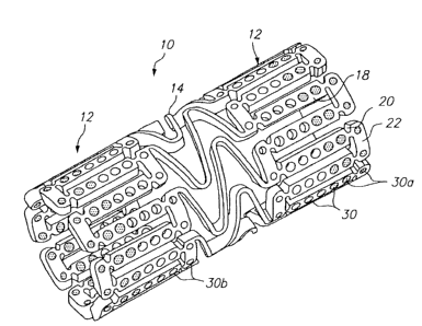
Figure 1 illustrates an expandable medical device having a plurality of holes
comprising a beneficial agent for delivery to tissue by the expandable
medical device. The expandable medical device 10 illustrated in Figure 1 is
cut from a tube of material to form a cylindrical expandable device. The
expandable medical device 10 includes a plurality of cylindrical sections 12
interconnected by a plurality of bridging elements 14. The bridging elements
14 allow the tissue supporting device to bend axially when passing through
the torturous path of vasculature to a deployment site and allow the device to
bend axially when necessary to match the curvature of a lumen to be
supported. Each of the cylindrical tubes 12 is formed by a network of
elongated struts 18 which are interconnected by ductile hinges 20 and
circumferential struts 22. During expansion of the medical device 10 the
ductile hinges 20 deform while the struts 18 are not deformed. Further
details of one example of the expandable medical device are described in
U.S. Patent No. 6,241,762.
As illustrated in Figure 1, the elongated struts 18 and circumferential struts
22 include openings 30, some of which comprise a beneficial agent for
delivery to the lumen in which the expandable medical device is implanted.
In addition, other portions of the device 10, such as the bridging elements
14, may include openings, as discussed below with respect to Figure 5.
Preferably, the openings 30 are provided in non-deforming portions of the
- 11 -
CA 02686527 2013-07-09
device 10, such as the struts 18, so that the openings are non-deforming
and the beneficial agent is delivered without risk of being fractured,
expelled,
or otherwise damaged during expansion of the device. A further description
of one example of the manner in which the beneficial agent may be loaded
within the openings 30 is described in U.S. Patent Application Ser. No.
09/948,987, filed Sep. 7, 2001.
The exemplary embodiments of the present invention may be further refined
lo by using Finite Element Analysis and other techniques to optimize
the
deployment of the beneficial agents within the openings 30. Basically, the
shape and location of the openings 30, may be modified to maximize the
volume of the voids while preserving the relatively high strength and rigidity
of the struts with respect to the ductile hinges 20. According to one
preferred
15 exemplary embodiment of the present invention, the openings have an
area
of at least 5 x 10⁻⁶ square inches, and preferably at least 7 x 10⁻⁶ square
inches. Typically, the openings are filled, from about fifty percent to about
ninety-five percent full of beneficial agent.
20 Definitions
The terms "agent," "therapeutic agent" or "beneficial agent" as used herein
are intended to have the broadest possible interpretation and are used to
include any therapeutic agent or drug, as well as inactive agents such as
25 barrier layers, carrier layers, therapeutic layers, or protective
layers.
The terms "drug" and "therapeutic agent" are used interchangeably to refer
to any therapeutically active substance that is delivered to a bodily lumen of
- 12 -
CA 02686527 2009-11-27
a living being to produce a desired, usually beneficial, effect. Beneficial
agents may include one or more drug or therapeutic agent.
The present invention is particularly well suited for the delivery of
antineoplastics, antiangiogenics, angiogenic factors, anti-inflammatories,
immuno-suppressants such as a rapamycin, antirestenotics, antiplatelet
agents, vasodilators, anti-thrombotics, antiproliferatives, such as
paclitaxel,
for example, and antithrombins, such as heparin, for example.
lo The term "erosion" means the process by which components of a medium or
matrix are bioresorbed and/or degraded and/or broken down by chemical or
physical or enzymatic processes. For example in reference to biodegradable
polymer matrices, erosion may occur by cleavage or hydrolysis of the
polymer chains, thereby increasing the solubility of the matrix and
suspended beneficial agents.
The term "erosion rate" is a measure of the amount of time it takes for the
erosion process to occur, usually reported in unit-area per unit-time.
The terms "matrix" or "bioresorbable matrix" are used interchangeably to
refer to a medium or material that, upon implantation in a subject, does not
elicit a detrimental response sufficient to result in the rejection of the
matrix.
The matrix typically does not provide any therapeutic responses itself,
though the matrix may contain or surround a beneficial agent, as defined
herein. A matrix is also a medium that may simply provide support, structural
integrity or structural barriers. The matrix may be polymeric, non-polymeric,
hydrophobic, hydrophilic, lipophilic, amphiphilic, and the like. In addition,
bioresorbable matrix shall also be understood to mean complete absorption
- 13 -
CA 02686527 2009-11-27
,
of the matrix by the body over time.
The term "openings" includes both through openings and recesses.
The term "pharmaceutically acceptable" refers to the characteristic of being
non-toxic to a host or patient and suitable for maintaining the stability of a
beneficial agent and allowing the delivery of the beneficial agent to target
cells or tissue.
lo The term "polymer" refers to molecules formed from the chemical union
of
two or more repeating units, called monomers. Accordingly, included within
the term "polymer" may be, for example, dimers, trimers and oligomers. The
polymer may be synthetic, naturally-occurring or semisynthetic. In preferred
form, the term "polymer" refers to molecules which typically have a Mw
greater than about 3000 and preferably greater than about 10,000 and a Mw
that is less than about 10 million, preferably less than about a million and
more preferably less than about 200,000. Examples of polymers include but
are not limited to, poly-.alpha.-hydroxy acid esters such as, polylactic acid
(PLLA or DLPLA), polyglycolic acid, polylactic-co-glycolic acid (PLGA),
polylactic acid-co-caprolactone; poly (block-ethylene oxide-block-lactide-co-
glycolide) polymers (PEO-block-PLGA and PEO-block-PLGA-block-PEO);
polyethylene glycol and polyethylene oxide, poly (block-ethylene oxide-
block-propylene oxide-block-ethylene oxide); polyvinyl pyrrolidone;
polyorthoesters; polysaccharides and polysaccharide derivatives such as
polyhyaluronic acid, poly (glucose), polyalginic acid, chitin, chitosan,
chitosan derivatives, cellulose, methyl cellulose, hydroxyethylcellulose,
hydroxypropylcellulose, carboxymethylcellulose, cyclodextrins and
substituted cyclodextrins, such as beta-cyclodextrin sulfobutyl ethers;
- 14 -
CA 02686527 2009-11-27
polypeptides and proteins, such as polylysine, polyglutamic acid, albumin;
polyanhydrides; polyhydroxy alkonoates such as polyhydroxy valerate,
polyhydroxy butyrate, and the like.
The term "primarily" with respect to directional delivery, refers to an amount
greater than about fifty percent of the total amount of therapeutic agent
provided to a blood vessel is provided in the primary direction.
The various exemplary embodiments of the present invention described
lo herein provide different beneficial agents in different openings in the
expandable device or beneficial agent in some openings and not in others.
The particular structure of the expandable medical device may be varied
without departing from the spirit of the invention. Since each opening is
filled
independently, individual chemical compositions and pharmacokinetic
properties may be imparted to the beneficial agent in each opening.
One example of the use of different beneficial agents in different openings in
an expandable medical device or beneficial agents in some openings and
not in others, is in addressing edge effect restenosis. As discussed above,
current generation coated stents may have a difficulty with edge effect
restenosis or restenosis occurring just beyond the edges of the stent and
progressing around the stent and into the interior luminal space.
The causes of edge effect restenosis in first generation drug delivery stents
are currently not well understood. It may be that the region of tissue injury
due to angioplasty and/or stent implantation extends beyond the diffusion
range of current generation beneficial agents such as paclitaxel, which tends
to partition strongly in tissue. A similar phenomenon has been observed in
- 15 -
CA 02686527 2009-11-27
radiation therapies in which low doses of radiation at the edges of stent have
proven stimulatory in the presence of an injury. In this case, radiating over
a
longer length until uninjured tissue is irradiated solved the problem. In the
case of drug delivery stents, placing higher doses or higher concentrations of
beneficial agents along the stent edges, placing different agents at the stent
edges which diffuse more readily through the tissue, or placing different
beneficial agents or combinations of beneficial agents at the edges of the
device may help to remedy the edge effect restenosis problem.
o Figure 1 illustrates an expandable medical device 10 with "hot ends" or
beneficial agent provided in the openings 30a at the ends of the device in
order to treat and reduce edge effect restenosis. The remaining openings
30b in the central portion of the device may be empty (as shown) or may
contain a lower concentration of beneficial agent.
Other mechanisms of edge effect restenosis may involve the cytotoxicity of
particular drugs or combinations of drugs. Such mechanisms could include a
physical or mechanical contraction of tissue similar to that seen in epidermal
scar tissue formation, and the stent might prevent the contractile response
within its own boundaries, but not beyond its edges. Further, the mechanism
of this latter form of restenosis may be related to sequelae of sustained or
local drug delivery to the arterial wall that is manifest even after the drug
itself is no longer present in the wall. That is, the restenosis may be a
response to a form of noxious injury related to the drug and/or the drug
carrier. In this situation, it might be beneficial to exclude certain agents
from
the edges of the device.
Figure 2 illustrates an alternate exemplary embodiment of an expandable
- 16 -
CA 02686527 2009-11-27
,
medical device 200 having a plurality of openings 230 in which the openings
230b in a central portion of the device are filled with a beneficial agent and
the openings 230a at the edges of the device remain empty. The device of
Figure 2 is referred to as having "cool ends."
In addition to use in reducing edge effect restenosis, the expandable medical
device 200 of Figure 2 may be used in conjunction with the expandable
medical device 10 of Figure 1 or another drug delivery stent when an initial
stenting procedure has to be supplemented with an additional stent. For
lo example, in some cases the device 10 of Figure 1 with "hot ends" or
a
device with uniform distribution of drug may be implanted improperly. If the
physician determines that the device does not cover a sufficient portion of
the lumen a supplemental device may be added at one end of the existing
device and slightly overlapping the existing device. When the supplemental
device is implanted, the device 200 of Figure 2 is used so that the "cool
ends" of the medical device 200 prevent double-dosing of the beneficial
agent at the overlapping portions of the devices 10, 200.
Figure 3 illustrates a further alternate exemplary embodiment of the
invention in which different beneficial agents are positioned in different
holes
of an expandable medical device 300. A first beneficial agent is provided in
holes 330a at the ends of the device and a second beneficial agent is
provided in holes 330b at a central portion of the device. The beneficial
agent may contain different drugs, the same drugs in different
concentrations, or different variations of the same drug. The exemplary
embodiment of Figure 3 may be used to provide an expandable medical
device 300 with either "hot ends" or "cool ends."
- 17 -
CA 02686527 2009-11-27
Preferably, each end portion of the device 300 which includes the holes
330a comprising the first beneficial agent extends at least one hole and up
to about fifteen holes from the edge. This distance corresponds to about
0.005 to about 0.1 inches from the edge of an unexpanded device. The
distance from the edge of the device 300 which includes the first beneficial
agent is preferably about one section, where a section is defined between
the bridging elements.
Different beneficial agents comprising different drugs may be disposed in
lo different openings in the stent. This allows the delivery of two or
more
beneficial agents from a single stent in any desired delivery pattern.
Alternately, different beneficial agents comprising the same drug in different
concentrations may be disposed in different openings. This allows the drug
to be uniformly distributed to the tissue with a non-uniform device structure.
The two or more different beneficial agents provided in the devices
described herein may comprise (1) different drugs; (2) different
concentrations of the same drug; (3) the same drug with different release
kinetics, i.e., different matrix erosion rates; or (4) different forms of the
same
drug. Examples of different beneficial agents comprising the same drug with
different release kinetics may use different carriers to achieve the elution
profiles of different shapes. Some examples of different forms of the same
drug include forms of a drug having varying hydrophilicity or lipophilicity.
In one example of the device 300 of Figure 3, the holes 330a at the ends of
the device are loaded with a first beneficial agent comprising a drug with a
high lipophilicity while holes 330b at a central portion of the device are
loaded with a second beneficial agent comprising the drug with a lower
- 18 -
CA 02686527 2009-11-27
lipophilicity. The first high lipophilicity beneficial agent at the "hot ends"
will
diffuse more readily into the surrounding tissue reducing the edge effect
restenosis.
The device 300 may have an abrupt transition line at which the beneficial
agent changes from a first agent to a second agent. For example, all
openings within 0.05 inches of the end of the device may comprise the first
agent while the remaining openings comprise the second agent. Alternately,
the device may have a gradual transition between the first agent and the
second agent. For example, a concentration of the drug in the openings may
progressively increase (or decrease) toward the ends of the device. In
another example, an amount of a first drug in the openings increases while
an amount of a second drug in the openings decreases moving toward the
ends of the device.
Figure 4 illustrates a further alternate exemplary embodiment of an
expandable medical device 400 in which different beneficial agents are
positioned in different openings 430a, 430b in the device in an alternating or
interspersed manner. In this manner, multiple beneficial agents may be
delivered to tissue over the entire area or a portion of the area supported by
the device. This exemplary embodiment will be useful for delivery of multiple
beneficial agents where combination of the multiple agents into a single
composition for loading in the device is not possible due to interactions or
stability problems between the beneficial agents.
In addition to the use of different beneficial agents in different openings to
achieve different drug concentrations at different defined areas of tissue,
the
loading of different beneficial agents in different openings may be used to
- 19 -
CA 02686527 2009-11-27
,
provide a more even spatial distribution of the beneficial agent delivered in
instances where the expandable medical device has a non-uniform
distribution of openings in the expanded configuration.
The use of different drugs in different openings in an interspersed or
alternating manner allows the delivery of two different drugs which may not
be deliverable if combined within the same polymer/drug matrix composition.
For example, the drugs themselves may interact in an undesirable way.
Alternately, the two drugs may not be compatible with the same polymers for
1 o formation of the matrix or with the same solvents for delivery of the
polymer/drug matrix into the openings.
Further, the exemplary embodiment of Figure 4 having different drugs in
different openings in an interspersed arrangement provide the ability to
deliver different drugs with very different desired release kinetics from the
same medical device or stent and to optimize the release kinetic depending
on the mechanism of action and properties of the individual agents. For
example, the water solubility of an agent greatly affects the release of the
agent from a polymer or other matrix. A highly water soluble compound will
generally be delivered very quickly from a polymer matrix, whereas, a
lipophilic agent will be delivered over a longer time period from the same
matrix. Thus, if a hydrophilic agent and a lipophilic agent are to be
delivered
as a dual drug combination from a medical device, it is difficult to achieve a
desired release profile for these two agents delivered from the same polymer
matrix.
The system of Figure 4 allows the delivery of a hydrophilic and a lipophilic
drug easily from the same stent. Further, the system of Figure. 4 allows the
- 20 -
CA 02686527 2009-11-27
delivery two agents at two different release kinetics and/or administration
periods. Each of the initial release in the first twenty-four hours, the
release
rate following the first twenty-four hours, the total administration period
and
any other characteristics of the release of the two drugs may be
independently controlled. For example the release rate of the first beneficial
agent can be arranged to be delivered with at least forty percent (preferably
at least fifty percent) of the drug delivered in the first twenty-four hours
and
the second beneficial agent may be arranged to be delivered with less than
twenty percent (preferably less than ten percent) of the drug delivered in the
lo first twenty-four hours. The administration period of the first
beneficial agent
may be about three weeks or less (preferably two weeks or less) and the
administration period of the second beneficial agent may be about four
weeks or more.
Restenosis or the recurrence of occlusion post-intervention, involves a
combination or series of biological processes. These processes include the
activation of platelets and macrophages. Cytokines and growth factors
contribute to smooth muscle cell proliferation and upregulation of genes and
metalloproteinases lead to cell growth, remodeling of extracellular matrix,
and smooth muscle cell migration. A drug therapy which addresses a
plurality of these processes by a combination of drugs may be the most
successfully antirestenotic therapy. The present invention provides a means
to achieve such a successful combination drug therapy.
The examples discussed below illustrate some of the combined drug
systems which benefit from the ability to release different drugs in different
holes or openings. One example of a beneficial system for delivering two
drugs from interspersed or alternating holes is the delivery of an anti-
- 21 -
CA 02686527 2009-11-27
inflammatory agent or an immunosuppressant agent in combination with an
antiproliferative agent or an anti-migratory agent. Other combinations of
these agents may also be used to target multiple biological processes
involved in restenosis. The anti-inflammatory agent mitigates the initial
s inflammatory response of the vessel to the angioplasty and stenting and
is
delivered at a high rate initially followed by a slower delivery over a time
period of about two weeks to match the peak in the development of
macrophages which stimulate the inflammatory response. The
antiproliferative agent is delivered at a relatively even rate over a longer
time
period to reduce smooth muscle cell migration and proliferation.
In addition to the examples that are be given below, the following chart in
Table 1 illustrates some of the useful two drug combination therapies which
may be achieved by placing the drugs into different openings in the medical
device.
- 22 -
CA 02686527 2013-07-09
Epothilone Imatinibmesylate Rapamycin Pime- PKC- Dexa- Fargli- ApoA-I
PTX2-Cda D Gleevec analog
crolimus 412 methasone tazar Insulin VIP milano
PTX x X x x x
x x x
2-CdA x X x x x
Epothilone D X x x x
x x
lmatinib x x x
mesylate
Gleevec
Rapamycin x x
x x x
analog
Pimecrolim us X X x
x x
PKC-412 x
x x x
Dexamethasone
x x
Farglitazar x
x
Insulin
VIP
ApoA-I milano
Table 1
The placement of the drugs in different openings allows the release kinetics
to be tailored to the particular agent regardless of the hydrophobilicity or
lipophobicity of the drug. Examples of some arrangements for delivery of a
lipophilic drug at a substantially constant or linear release rate are
described
in WO 04/110302 published on Dec. 23, 2004.
Examples of some of the arrangements for
delivery of hydrophilic drug are described in WO 04/043510, published on
May 27, 2004. = The
hydrophilic drugs listed above include CdA, Gleevec, VIP, insulin, and ApoA-
1 milano. The lipophilic drugs listed above include paclitaxel, Epothilone D,
rapamycin, pimecrolimus, PKC-412 and Dexamethazone. Farglitazar is
partly liphophillic and partly hydrophilic.
- 23 -
CA 02686527 2009-11-27
In addition to the delivery of multiple of drugs to address different
biological
processes involved in restenosis, the present invention may deliver two
different drugs for treatment of different diseases from the same stent. For
example, a stent may deliver an anti-proliferative, such as paclitaxel or a
limus drug from one set of openings for treatment of restenosis while
delivering a myocardial preservative drug, such as insulin, from other
openings for the treatment of acute myocardial infarction.
In many of the known expandable devices and for the device illustrated in
Figure 5 the coverage of the device 500 is greater at the cylindrical tube
portions 512 of the device than at the bridging elements 514. Coverage is
defined as the ratio of the device surface area to the area of the lumen in
which the device is deployed. When a device with varying coverage is used
to deliver a beneficial agent contained in openings in the device, the
beneficial agent concentration delivered to the tissue adjacent the
cylindrical
tube portions 512 is greater that the beneficial agent delivered to the tissue
adjacent the bridging elements 514. In order to address this longitudinal
variation in device structure and other variations in device coverage which
lead to uneven beneficial agent delivery concentrations, the concentration of
the beneficial agent may be varied in the openings at portions of the device
to achieve a more even distribution of the beneficial agent throughout the
tissue. In the case of the exemplary embodiment illustrated in Figure 5, the
openings 530a in the tube portions 512 include a beneficial agent with a
lower drug concentration than the openings 530b in the bridging elements
514. The uniformity of agent delivery may be achieved in a variety of
manners including varying the drug concentration, the opening diameter or
shape, the amount of agent in the opening (i.e., the percentage of the
- 24 -
CA 02686527 2013-07-09
opening filed), the matrix material, or the form of the drug.
Another example of an application for the use of different beneficial agents
in
different openings is in an expandable medical device 600, as illustrated in
Figure 6, configured for use at a bifurcation in a vessel. Bifurcation devices
include a side hole 610 which is positioned to allow blood flow through a side
branch of a vessel. One example of a bifurcation device is described in U.S.
Patent No. 6,293,967.
The bifurcation device 600 includes the side hole feature 610
o interrupting the regular pattern of beams which form a remainder of the
device. Since an area around a bifurcation is a particularly problematic area
for restenosis, a concentration of an antiproliferative drug may be increased
in openings 630a at an area surrounding the side hole 610 of the device 600
to deliver increased concentrations of the drug where needed. The
remaining openings 630b in an area away from the side opening contain a
beneficial agent with a lower concentration of the antiproliferative. The
increased antiproliferative delivered to the region surrounding the
bifurcation
hole may be provided by a different beneficial agent containing a different
drug or a different beneficial agent containing a higher concentration of the
same drug.
In addition to the delivery of different beneficial agents to the mural or
abluminal side of the expandable medical device for treatment of the vessel
wall, beneficial agents may be delivered to the luminal side of the
expandable medical device to prevent or reduce thrombosis. Drugs which
are delivered into the blood stream from the lumina( side of the device may
be located at a proximal end of the device or a distal end of the device.
- 25 -
CA 02686527 2009-11-27
The methods for loading different beneficial agents into different openings in
an expandable medical device may include known techniques such as
dipping and coating and also known piezoelectric micro-jetting techniques.
Micro-injection devices may be computer controlled to deliver precise
amounts of two or more liquid beneficial agents to precise locations on the
expandable medical device in a known manner. For example, a dual agent
jetting device may deliver two agents simultaneously or sequentially into the
openings. When the beneficial agents are loaded into through openings in
the expandable medical device, a luminal side of the through openings may
be blocked during loading by a resilient mandrel allowing the beneficial
agents to be delivered in liquid form, such as with a solvent. The beneficial
agents may also be loaded by manual injection devices.
EXAMPLE 1
Figure 7 illustrates a dual drug stent 700 having an anti-inflammatory agent
and an antiproliferative agent delivered from different holes in the stent to
provide independent release kinetics of the two drugs which are specifically
programmed to match the biological processes of restenosis. According to
this example, the dual drug stent includes an anti-inflammatory agent
pimecrolimus in a first set of openings 710 in combination with the
antiproliferative agent paclitaxel in a second set of openings 720. Each
agent is provided in a matrix material within the holes of the stent in a
specific inlay arrangement designed to achieve the release kinetics
illustrated in Figure 8. Each of the drugs are delivered primarily murally for
treatment of restenosis.
As illustrated in Figure 7, pimecrolimus is provided in the stent for
directional
- 26 -
CA 02686527 2009-11-27
delivery to the mural side of the stent by the use of a barrier 712 at the
luminal side of the hole. The barrier 712 is formed by a biodegradable
polymer. The pimecrolimus is loaded within the holes in a manner which
creates a release kinetics having dual phases. A first phase of the release of
pimecrolimus is provided by a murally located region 716 of the matrix which
has a fast release formulation including pimecrolimus and biodegradable
polymer (PLGA) with a high percentage of drug, such as about ninety
percent drug to about ten percent polymer. A second phase of the release is
provided by a central region 714 of the matrix with pimecrolimus and
lo biodegradable polymer (PLGA) in a ratio of about fifty percent drug to
fifty
percent polymer. As may be seen on the graph of Figure 8, the first phase of
the pimecrolimus release delivers about fifty percent of the loaded drug in
about the first twenty-four hours. The second phase of the release delivers
the remaining fifty percent over about two weeks. This release is specifically
programmed to match the progression of the inflammatory process following
angioplasty and stenting. In addition to or as an alternative to changing the
drug concentration between the two regions to achieve the two phase
release, different polymers or different comonomer ratios of the same
polymer may be used in two drug different regions to achieve the two
different release rates.
The paclitaxel is loaded within the openings 720 in a manner which creates a
release kinetic having a substantially linear release after the first
approximately twenty-four hours, as illustrated in Figure 8. The paclitaxel
openings 720 are loaded with three regions including a base region 722 of
primarily polymer with minimal drug at a luminal side of the hole, a central
region 724 with paclitaxel and polymer (PLGA) provided in a concentration
gradient, and a cap region 726 with primarily polymer which controls release
- 27 -
CA 02686527 2009-11-27
of the paclitaxel. The paclitaxel is released with an initial release in the
first
day of about five to about fifteen percent of the total drug load followed by
a
substantially linear release for about twenty to ninety days. Additional
examples of arrangements for paclitaxel in the holes with a concentration
gradient are described in WO 04/110302 set forth above.
Figure 7 illustrates the drug, barrier, and cap regions as distinct regions
within the openings for ease of illustration. It should be understood that
these regions indistinct and formed by a blending of the different areas.
o Thus, although the barrier layers are primarily polymer without drug,
depending on the manufacturing processes employed, some small amount
of drug of the subsequent region can be incorporation into the barrier region.
The amount of the drugs delivered varies depending on the size of the stent.
For a three mm by six mm stent the amount of pimecrolimus is about fifty to
about three hundred micrograms preferably about one hundred to about two
hundred fifty micrograms. The amount of paclitaxel delivered from this stent
is about five to about fifty micrograms preferably about ten to about thirty
micrograms. In one example, about two hundred micrograms of
pimecrolimus and about twenty micrograms of paclitaxel are delivered. The
drugs may be located in alternating holes in the stent. However, in view of
the large difference in the doses to be delivered between the two drugs, it
may be desirable to place the paclitaxel in every third of fourth hole in the
stent. Alternatively, the holes for delivery of the low dose drug (paclitaxel)
may be made smaller than the holes for the high dose.
The polymer/drug inlays are formed by computer controlled piezoelectric
injection techniques as described in WO 04/026182 published on Apr. 1,
- 28 -
CA 02686527 2013-07-09
2004.
The inlays of
the first agent may be formed first followed by the inlays of the second agent
using the piezoelectric injector. Alternately, the system of WO 04/02182 may
be equipped with dual piezoelectric dispensers for dispensing the two agents
at the same time.
EXAMPLE 2
TM
According to this example, the dual drug stent includes the Gleevec in the
o first set of openings 710 in combination with the antiproliferative
agent
paclitaxel in the second set of openings 720. Each agent is provided in a
matrix material within the holes of the stent in a specific inlay arrangement
designed to achieve the release kinetics illustrated in Figure 8.
The Gleevec is delivered with a two phase release including a high initial
release in the first day and then a slow release for one to two weeks. The
first phase of the Gleevec release delivers about fifty percent of the loaded
drug in about the first twenty-four hours. The second phase of the release
delivers the remaining fifty percent over about one-two weeks. The paclitaxel
= is loaded within the openings 720 in a manner which creates a release
kinetics having a substantially linear release after the first approximately
twenty-four hours, as illustrated in Figure 8 and as described above in
Example 1.
The amount of the drugs delivered varies depending on the size of the stent.
For a three mm by six mm stent the amount of Gleevec is about two hundred
to about five hundred micrograms, preferably about three hundred to about
four hundred micrograms. The amount of paclitaxel delivered from this stent
- 29 -
CA 02686527 2009-11-27
is about five to about fifty micrograms, preferably about ten to about thirty
micrograms. As in Example 1, the drugs may be located in alternating holes
in the stent or interspersed in a non-alternating manner. The polymer/drug
inlays are formed in the manner described in Example 1.
EXAMPLE 3
According to this example, the dual drug stent includes the PKC-412 (a cell
growth regulator) in the first set of openings in combination with the
io antiproliferative agent paclitaxel in the second set of openings.
Each agent is
provided in a matrix material within the holes of the stent in a specific
inlay
arrangement designed to achieve the release kinetics discussed below.
The PKC-412 is delivered at a substantially constant release rate after the
15 first approximately twenty-four hours, with the release over a
period of about
four to sixteen weeks, preferably about six to twelve weeks. The paclitaxel is
loaded within the openings in a manner which creates a release kinetic
having a substantially linear release after the first approximately twenty-
four
hours, with the release over a period of about four to sixteen weeks,
20 preferably about six to twelve weeks.
The amount of the drugs delivered varies depending on the size of the stent.
For a three mm by six mm stent the amount of PKC-412 is about one
hundred to about four hundred micrograms, preferably about one hundred
25 fifty to about two hundred fifty micrograms. The amount of
paclitaxel
delivered from this stent is about five to about fifty micrograms, preferably
about ten to about thirty micrograms. As in Example 1, the drugs may be
located in alternating holes in the stent or interspersed in a non-alternating
- 30 -
CA 02686527 2009-11-27
manner. The polymer/drug inlays are formed in the manner described in
Example 1.
Therapeutic Agents
The present invention relates to the delivery of anti-restenotic agents
including paclitaxel, rapamycin, cladribine (CdA), and their derivatives, as
well as other cytotoxic or cytostatic agents and microtubule stabilizing
agents. Although anti-restenotic agents have been primarily described
lo herein, the present invention may also be used to deliver other
agents alone
or in combination with anti-restenotic agents. Some of the therapeutic agents
for use with the present invention which may be transmitted primarily
luminally, primarily murally, or both and may be delivered alone or in
combination include, but are not limited to, antiproliferatives,
antithrombins,
immunosuppressants including sirolimus, antilipid agents, anti-inflammatory
agents, antineoplastics, antiplatelets, angiogenic agents, anti-angiogenic
agents, vitamins, antimitotics, metalloproteinase inhibitors, NO donors,
estradiols, anti-sclerosing agents, and vasoactive agents, endothelial growth
factors, estrogen, beta blockers, AZ blockers, hormones, statins, insulin
growth factors, antioxidants, membrane stabilizing agents, calcium
antagonists, retenoid, bivalirudin, phenoxodiol, etoposide, ticlopidine,
dipyridamole, and trapidil alone or in combinations with any therapeutic
agent mentioned herein. Therapeutic agents also include peptides,
lipoproteins, polypeptides, polynucleotides encoding polypeptides, lipids,
protein-drugs, protein conjugate drugs, enzymes, oligonucleotides and their
derivatives, ribozymes, other genetic material, cells, antisense,
oligonucleotides, monoclonal antibodies, platelets, prions, viruses, bacteria,
and eukaryotic cells such as endothelial cells, stem cells, ACE inhibitors,
- 31 -
CA 02686527 2009-11-27
monocyte/macrophages or vascular smooth muscle cells to name but a few
examples. The therapeutic agent may also be a pro-drug, which metabolizes
into the desired drug when administered to a host. In addition, therapeutic
agents may be pre-formulated as microcapsules, microspheres,
microbubbles, liposomes, niosomes, emulsions, dispersions or the like
before they are incorporated into the therapeutic layer. Therapeutic agents
may also be radioactive isotopes or agents activated by some other form of
energy such as light or ultrasonic energy, or by other circulating molecules
that can be systemically administered. Therapeutic agents may perform
lo multiple functions including modulating angiogenesis, restenosis, cell
proliferation, thrombosis, platelet aggregation, clotting, and vasodilation.
Anti-inflammatories include but are not limited to non-steroidal anti-
inflammatories (NSAID), such as aryl acetic acid derivatives, e.g.,
Diclofenac; aryl propionic acid derivatives, e.g., Naproxen; and salicylic
acid
derivatives, e.g., Diflunisal. Anti-inflammatories also include
glucocoriticoids
(steroids) such as dexamethasone, aspirin, prednisolone, and triamcinolone,
pirfenidone, meclofenamic acid, tranilast, and nonsteroidal anti-
inflammatories. Anti-inflammatories may be used in combination with
antiproliferatives to mitigate the reaction of the tissue to the
antiproliferative.
The agents may also include anti-lymphocytes; anti-macrophage
substances; immunomodulatory agents; cyclooxygenase inhibitors; anti-
oxidants; cholesterol-lowering drugs; statins and angiotens in converting
enzyme (ACE); fibrinolytics; inhibitors of the intrinsic coagulation cascade;
antihyperlipoproteinemics; and anti-platelet agents; anti-metabolites, such as
2-chlorodeoxy adenosine (2-CdA or cladribine); immuno-suppressants
including sirolimus, everolimus, tacrolimus, etoposide, and mitoxantrone;
- 32 -
CA 02686527 2009-11-27
anti-leukocytes such as 2-CdA, IL-1 inhibitors, anti-CD116/CD18 monoclonal
antibodies, monoclonal antibodies to VCAM or ICAM, zinc protoporphyrin;
anti-macrophage substances such as drugs that elevate NO; cell sensitizers
to insulin including glitazones; high density lipoproteins (HDL) and
s derivatives; and synthetic facsimile of HDL, such as lipator,
lovestatin,
pranastatin, atorvastatin, simvastatin, and statin derivatives; vasodilators,
such as adenosine, and dipyridamole; nitric oxide donors; prostaglandins
and their derivatives; anti-TNF compounds; hypertension drugs including
Beta blockers, ACE inhibitors, and calcium channel blockers; vasoactive
io substances including vasoactive intestinal polypeptides (VIP); insulin;
cell
sensitizers to insulin including glitazones, P par agonists, and metformin;
protein kinases; antisense oligonucleotides including resten-NG; antiplatelet
agents including tirofiban, eptifibatide, and abciximab; cardio protectants
including, VIP, pituitary adenylate cyclase-activating peptide (PACAP),
15 apoA-I milano, amlodipine, nicorandil, cilostaxone, and thienopyridine;
cyclooxygenase inhibitors including COX-1 and COX-2 inhibitors; and
petidose inhibitors which increase glycolitic metabolism including
omnipatrilat. Other drugs which may be used to treat inflammation include
lipid lowering agents, estrogen and progestin, endothelin receptor agonists
20 and interleukin-6 antagonists, and Adiponectin. Therapeutic agents may
also include phosphodiesterase inhibitors (PDEi), such as cilastazol and
adenosine receptor agonists, preferably A2A receptor, agonists such as
regadenoson.
25 Agents may also be delivered using a gene therapy-based approach in
combination with an expandable medical device. Gene therapy refers to the
delivery of exogenous genes to a cell or tissue, thereby causing target cells
to express the exogenous gene product. Genes are typically delivered by
- 33 -
CA 02686527 2013-07-09
either mechanical or vector-mediated methods.
Some of the agents described herein may be combined with additives which
preserve their activity. For example additives including surfactants,
antacids,
antioxidants, and detergents may be used to minimize denaturation and
aggregation of a protein drug. Anionic, cationic, or nonionic surfactants may
be used. Examples of nonionic excipients include but are not limited to
sugars including sorbitol, sucrose, trehalose; dextrans including dextran,
carboxy methyl (CM) dextran, diethylamino ethyl (DEAE) dextran; sugar
derivatives including D-glucosaminic acid, and D-glucose diethyl mercaptal;
synthetic polyethers including polyethylene glycol (PEO) and polyvinyl
pyrrolidone (PVP); carboxylic acids including D-lactic acid, glycolic acid,
and
propionic acid; surfactants with affinity for hydrophobic interfaces including
n-
dodecyl-.beta.-D-maltoside, n-octykbeta.-D-glucoside, PEO-fatty acid esters
=stearate (myrj 59) or oleate), PEO-sorbitan-fatty acid esters (e.g.
Tweenm80, PEO-20 sorbitan monooleate), sorbitan-fatty acid esters (e.g.
SPAN(60, sorbitan monostearate), PEO-glyceryl-fatty acid esters; glyceryl
fatty acid esters (e.g. glyceryl monostearate), PEO-hydrocarbon-ethers (e.g.
PEO-10 oleyl ether;Tritorr X-100; and Lubrciim. Examples of ionic detergents
include but are not limited to fatty acid salts including calcium stearate,
magnesium stearate, and zinc stearate; phospholipids including lecithin and
phosphatidyl choline; (PC) CM-PEG; cholic acid; sodium dodecyl sulfate
(SDS); docusate (AOT); and taumocholic acid.
In accordance with another exemplary embodiment, a stent or intraluminal
scaffold as described herein, may be coated with an anti-thrombotic agent in
addition to one or more therapeutic agents deposited in the holes or
openings. In one exemplary embodiment, the stent may be fabricated with
- 34 -
CA 02686527 2009-11-27
the openings therein and prior to the addition or deposition of other
therapeutic agents into the openings, an anti-thrombotic agent, with or
without a carrier vehicle (polymer or polymeric matrix) may be affixed to the
stent or a portion thereof. In this exemplary embodiment, the luminal and
abluminal surfaces of the stent may be coated with the anti-thrombotic agent
or coating, as well as the surfaces of the walls of the openings. In an
alternative exemplary embodiment, a stent may first be coated with an anti-
thrombotic agent or coating and then the openings may be fabricated. In
this exemplary embodiment, only the luminal and abluminal surfaces would
lo have the anti-thrombotic agent or coating and not the walls of the
openings.
In each of these embodiments any number of anti-thrombotic agents may
be affixed to all or portions of the stents. In addition, any number of known
techniques may be utilized to affix the anti-thrombotic agent to the stent
such
as that utilized with the HEPACOATTm on the Bx Velocity Coronary Stent
from Cordis Corporation. Alternatively, the stents may be manufactured with
a rough surface texture or have a micro-texture to enhance cell attachment
and endothelialization, independently of or in addition to the anti-thrombotic
coating. In addition, any number of therapeutic agents may be deposited
into the openings and different agents may be utilized in different regions of
the stent.
As described above, it is important to note that any number of drugs and or
agents may be utilized in accordance with the present invention including:
antiproliferative/antimitotic agents including natural products such as vinca
alkaloids (i.e. vinblastine, vincristine, and vinorelbine), paclitaxel,
epidipodophyllotoxins (i.e. etoposide, teniposide), antibiotics (dactinomycin
(actinomycin D) daunorubicin, doxorubicin and idarubicin), anthracyclines,
mitoxantrone, bleomycins, plicamycin (mithramycin) and mitomycin,
- 35 -
CA 02686527 2009-11-27
enzymes (L-asparaginase which systemically metabolizes L-asparagine and
deprives cells which do not have the capacity to synthesize their own
asparagine); antiplatelet agents such as G(GP)11bIlla inhibitors and
vitronectin
receptor antagonists; antiproliferative/antimitotic alkylating agents such as
nitrogen mustards (mechlorethamine, cyclophosphamide and analogs,
melphalan, chlorambucil), ethylenimines and methylmelamines
(hexamethylmelamine and thiotepa), alkyl sulfonates-busulfan, nirtosoureas
(carmustine (BCNU) and analogs, streptozocin), trazenes ¨ dacarbazinine
(DTIC); antiproliferative/antimitotic antimetabolites such as folic acid
lo analogs (methotrexate), pyrimidine analogs (fluorouracil, floxuridine,
and
cytarabine), purine analogs and related inhibitors (mercaptopurine,
thioguanine, pentostatin and 2-chlorodeoxyadenosine {cladribine}); platinum
coordination complexes (cisplatin, carboplatin), procarbazine, hydroxyurea,
mitotane, aminoglutethimide; hormones (i.e. estrogen); anticoagulants
(heparin, synthetic heparin salts and other inhibitors of thrombin);
fibrinolytic
agents (such as tissue plasminogen activator, streptokinase and urokinase),
aspirin, dipyridamole, ticlopidine, clopidogrel, abciximab; antimigratory;
antisecretory (breveldin); antiinflammatory: such as adrenocortical steroids
(cortisol, cortisone, fludrocortisone, prednisone, prednisolone, 6a-
methylprednisolone, triamcinolone, betamethasone, and dexamethasone),
non-steroidal agents (salicylic acid derivatives i.e. aspirin; para-
aminophenol
derivatives i.e. acetominophen; indole and indene acetic acids
(indomethacin, sulindac, and etodalac), heteroaryl acetic acids (tolnnetin,
diclofenac, and ketorolac), arylpropionic acids (ibuprofen and derivatives),
anthranilic acids (mefenamic acid, and meclofenamic acid), enolic acids
(piroxicam, tenoxicam, phenylbutazone, and oxyphenthatrazone),
nabumetone, gold compounds (auranofin, aurothioglucose, gold sodium
thiomalate); immunosuppressives: (cyclosporine, tacrolimus (FK-506),
- 36 -
CA 02686527 2009-11-27
sirolimus (rapamycin), azathioprine, mycophenolate mofetil); angiogenic
agents: vascular endothelial growth factor (VEGF), fibroblast growth factor
(FGF) platelet derived growth factor (PDGF), erythropoetin; angiotensin
receptor blocker; nitric oxide donors; anti-sense oligionucleotides and
combinations thereof; cell cycle inhibitors, mTOR inhibitors, and growth
factor signal transduction kinase inhibitors.
Referring now to Figure 9A, 9B and 90, there is illustrated a diagrammatic
representation of a portion of a stent.
As illustrated in Figure 9A the stent 900 comprises a plurality of
substantially
circular openings 902. In this exemplary embodiment, the plurality of
substantially circular openings 902 extend through the wall of the stent 900.
In other words, the plurality of substantially circular openings 902 extend
from the abluminal surface of the stent 904 to the abluminal surface of the
stent 906, wherein the wall thickness is defined as the distance between the
luminal and abluminal surfaces. In other embodiments; however, the
openings need not extend through the wall of the stent 900. For example,
the openings or reservoirs may extend partially from either the luminal or
abluminal surfaces or both. The stent 900 in Figure 9A has untreated
surfaces 904 and 906 and empty openings 902.
In Figure 9B, at least one surface has been coated with a therapeutic agent
908. The therapeutic agent preferably comprises an anti-thrombotic agent
such as heparin; however, any anti-thrombotic agent may be utilized. The
anti-thrombotic agent may be affixed utilizing any technique as briefly
described above. In this exemplary embodiment, both the abluminal and
luminal surfaces have an anti-thrombotic agent affixed thereto. In addition,
- 37 -
CA 02686527 2009-11-27
as there is nothing in the plurality of substantially circular openings 902 at
this juncture, the walls of the openings 902 may also have some anti-
thrombotic agent affixed thereto. The amount of anti-thrombotic agent
affixed to the walls of the openings 910 depends on how the agent is affixed.
For example, if the agent is affixed by dip coating, the walls of the openings
will have more agent affixed thereto than if the agent is affixed utilizing a
spray coating technique. As described herein, in this exemplary
embodiment, all exposed surfaces have a substantial anti-thrombotic coating
affixed thereto; however, in alternate exemplary embodiments, only specific
io surfaces may have an anti-thrombotic affixed thereto. For example, in
one
exemplary embodiment, only the surface in contact with the blood may be
treated with the anti-thromobotic agent. In yet another alternate exemplary
embodiment, one or both surfaces may be coated with the anti-thrombotic
agent while the walls of the openings are not. This may be accomplished in
a number of ways including plugging the openings prior to coating or
creating the openings after the anti-thrombotic agent is affixed.
Figure 9C illustrates a completed stent in accordance with this exemplary
embodiment. As illustrated in this figure, the plurality of substantially
circular
openings 902 have been filled with one or more therapeutic agents for
treating vascular diseases such as restenosis and inflammation or any other
dieses as described herein. Each opening 902 may be filled with the same
therapeutic agent or different agents as described in detail above. As
illustrated in the figure, these different agents 912, 914 and 916 are used in
a particular pattern; however, as detailed above, any combination is possible
as well as utilizing a singe agent with different concentrations. The drugs,
such as a rapamycin, may be deposited in the openings 902 in any suitable
manner. Techniques for depositing the agent include micro-pippetting
- 38 -
CA 02686527 2009-11-27
and/or ink-jet filling methods. In one exemplary embodiment, the drug filling
may be done so that the drug and/or drug/polymer matrix in the opening will
be below the level of the stent surfaces so that there is no contact with the
surrounding tissue. Alternately, the openings may be filled so that the drug
and/or drug/polymer matrix may contact the surrounding tissue. In addition,
the total dose of each of the drugs, if multiple drugs are utilized, may be
designed with maximal flexibility. Additionally, the release rate of each of
the
drugs may be controlled individually. For example, the openings near the
ends may contain more drugs to treat edge restenosis.
In accordance with this exemplary embodiment, the hole or openings may be
configured not only for the most efficacious drug therapy, but also for
creating a physical separation between different drugs. This physical
separation may aid in preventing the agents from interacting.
As used herein, rapamycin includes rapamycin and all analogs, derivatives
and conjugates that bind to FKBP12, and other imnnunophilins and
possesses the same pharnnacologic properties as rapamycin including
inhibition of TOR. In addition, all drugs and agents described herein in their
analogs, derivatives and conjugates.
As described herein, a stent having through-holes, holes, reservoirs or
openings therein may be coated with an anti-thrombotic agent and/or drug or
combination of drugs such as those described herein, and the openings filled
with one or more therapeutic agents alone or in combination with one or more
polymers. Essentially, the stent may be fabricated with the openings therein
and prior to the addition or deposition of therapeutic agents alone or in
combination with one or more polymers into the openings, an anti-thrombotic
- 39 -
CA 02686527 2009-11-27
agent, with or without a carrier vehicle, may be affixed to the stent or a
portion
thereof. In the exemplary embodiment as described herein, the luminal and
abluminal surfaces of the stent as well as the surfaces of the walls of the
openings may be coated with the anti-thromobotic agent. In this exemplary
s embodiment, the anti-thrombotic agent comprises heparin or its various
derivatives such as low molecular-weight heparin (LMWH), although any
number of suitable anti-thrombotic agents may be utilized. Heparin and/or
LMWH have very high negative charges.
The entire surface of the stent described herein, including the interior
surfaces of the through-holes or openings that become reservoirs for the
therapeutic agent and/or combination polymers and therapeutic agent, is first
given a covalently bonded heparin coating. The heparin coating itself is
bonded to the metal surface of the stent by its own primer comprising
alternating layers of poly(ethyleneimine), a strongly cationic polymer known
by the abbreviation PEI, and dextran sulfate, a polymeric anion. The
application of this type of primer is known in the art and is set forth in a
number of patents, including U.S. Patent Nos. 5,213,898, 5,049,403,
6,461,665 and 6,767,405. More specifically, the heparin is covalently
bonded to the primer, including the PEI-dextran sulfate layers, which is in
turn bonded to the metal surface. Once all surfaces are coated with the
heparin mixture, each of the holes or reservoirs are filled utilizing one of
the
processes described herein.
In accordance with another exemplary embodiment, the present invention is
directed to primer compositions and configurations for improving the adhesion
of a drug delivery matrix, e.g. therapeutic agent and polymer combination, to
a
heparin coated surface of a medical device, for example, a stent. The present
- 40 -
CA 02686527 2009-11-27
invention is particularly advantageous where the heparin coating is covalently
bonded to a metallic or polymer surface of the medical device. In the present
invention, the primer preferably comprises a high molecular weight component
or a low molecular weight component, and the drug delivery matrix comprises
a drug and/or other beneficial agent and an excipient, preferably a polymeric
excipient. In addition, the primer may also preferably comprise a material
having an opposite electrical charge and similar charge density to that of the
underlying layer, for example, heparin.
The concept of a primer on top of a heparin layer or coating to increase the
bonding of a heparin coated surface to any other matrix or coating is unique
given that typically the heparin surface is utilized to confer anti-
thromobotic
properties and hence will not be covered in practical uses. In the present
invention, it is only the interior wall surfaces of the holes or openings in
the
stent that hold the drug-polymer reservoirs that will be covered with the
primer
of the present invention, thus increasing the adhesion between the two layers
and limiting the potential loss of the drug-polymer matrix without
substantially
affecting the heparin surface outside the reservoirs. It is important to note
that
the heparin blocking primers in accordance with the present invention are
biocompatible in their original intended uses.
The primer of the present invention may be utilized with any type of stent. In
the exemplary embodiment described herein, the primer is utilized with the
stent or stents illustrated in Figures 1, 2, 3 and 4.
In accordance with one exemplary embodiment, the primer comprises
polymer-poly(ethyleneimine) conjugates, for example polylactic-co-glycolic
acid
(PLGA) and poly(ethyleneimine) PEI and/or PLGA-protamine.
- 41 -
CA 02686527 2009-11-27
,
Poly(ethyleneimine) is a strongly cationic polymer that binds to certain
negatively charged proteins or polysaccharides. In addition to PEI, the other
material useful in this conjugate is protamine. Protamine is an approved low
molecular weight protein drug that is utilized as an antidote to heparin. It
is
sparsely solution in water. In this manner, the primer may simultaneously
interact strongly with both the heparin coating and the drug containing
matrix,
thus improving the adhesion between the two substances. Since heparin is a
poly(anionic) species, it is anticipated that a poly(cationic) species such as
protamine would bond well to the heparin, but would be sufficiently
hydrophobic in the other sections of its structure to allow good bonding of
the
PLGA component of the drug polymer matrix in the reservoir.
The bonding reactions between PLGA and PEI and PEI and heparin may be
ionic-bonding or covalent-bonding reactions. Figure 10 illustrates an
example of covalent-bonding between PLGA and PEI. More specifically,
Figure 10 illustrates the conjugation reaction between PLGA with a
carboxylic acid end group and low molecular weight PEI. Alternatively, the
primer may comprise a high molecular weight PEI or a branched PEI.
Referring to Figure 11, there is illustrated the conjugation reaction between
PLGA with a carboxylic acid end group and a high molecular weight or
branched PEI. As illustrated, the reaction may be configured for a one-to-
one ratio or a conjugate of PLGA-PEI-PLGA for a 2:1 ratio between PLGA
and PEI.
The table below, Table 2, illustrates the effectiveness of PEI as a primer for
increasing the adhesion of the drug/polymer complex to the heparin coated
surfaces. The test stents are immersed in a testing medium comprising a
phosphate buffer saline and bovine serum albumin which simulates
- 42 -
CA 02686527 2009-11-27
physiological fluid conditions. The drug/polymer complex comprises a
rapamycin and PLGA.
Percent (%) of Empty Reservoirs versus Initial Total Reservoirs (after
immersion in
PBS-BSA)
Heparin coated
Initial Day 7 Day 14 Day 21 Day 28 D3a0Y Day 35 Day 42 Day 49 Day 60 Day 75
Day 90
stent
Avg 0% -- 0% 0.3% 3.1% -- 3.7% 4.1% 4.8% 4.8% 5.1% 5.3%
_
No primer Stdev 0% -- 0% 0.4% 2.1% -- 2.0%
2.00/o 1.2% 1.2% 1.3% 1.5%
RSD n/a -- n/a 124.9% 68.3% -- 56.0% 48.5% 25.3% 25.3%
25.1% 28.4%
Avg 0.0% 0.0 A. -- -- -- 0.0% 0.0%
- _
Primed with 0.25% PEI
Stdev 0.00/o 0.0% -- -- -- 0.0% 0.0%
(linear) in Water
RSD n/a n/a -- -- -- n/a
n/a
Avg 0% -- 0% 0% 0% -- 0.1% 0.1%
0.1% 0.1% 0.1% 0.1%
Primed with 0.5% PEI
Stdev 0% -- 0% 0% 0% -- 0% 0% 0% 0% 0% 0%
(linear) in Water
_
RSD n/a -- n/a n/a n/a -- n/a n/a
n/a n/a n/a n/a
Avg 00/o -- 0% 0% 0% -- 0.1% 0.1%
0.1% 0.1% 0.1% 0.1%
_
Primed with 0.5% PEI
Stdev 0% --0% 0% 0% -- 0% 0% 0% 0% 0% 0%
(linear) in DMSO _
RSD n/a -- n/a n/a n/a -- n/a n/a
n/a n/a n/a n/a
. -
Avg 0% -- 0% 0% 0% -- 0% 0% 0% 0% 0% 0%
_ .
Primed with 0.5% PEI
Stdev 0% --0% 0% 0% -- 0% 0% 0% 0% 0% 0%
(branched) in Water . .
RSD n/a -- n/a n/a n/a -- n/a n/a
n/a n/a n/a n/a
Avg 0% -- 0% 0% 0% -- 0% 0% 0% 0% 0% 0%
_
Primed with 0.5% PEI
Stdev 0% -- 0% 0% 0% -- 0% 0% 0% 0% 00/o 0%
(branched) in DMSO
RSD n/a -- n/a n/a n/a -- n/a n/a
n/a n/a n/a n/a
Avg 0.0% 0.0% -- -- -- 0.0% 0.0%
Primed with 0.75% PEI Stdev 0.0% 0.00/o -- -- --
0.0% 0.0%
(linear) in Water _ - . _. _
RSD n/a n/a -- -- -- n/a
n/a
s Table 2
In an alternate exemplary embodiment, the primer may comprise low
molecular weight complexing cations to heparin, including benzalkonium
chloride and/or oligomeric arginine peptides, or high molecular weight
- 43 -
CA 02686527 2009-11-27
complexing cations, including polylysine, poly(arginine), protamine,
poly(dimethylaminoethyl) methacrylate or poly (dimethylaminoethyl) acrylate.
In accordance with the present invention, the process for increasing adhesion
of the drug complex to the heparin may include the application of the adhesion
promoting primer followed by polymer/drug fill solution or the application of
the
adhesion promoting primer followed by carboxyl-ended PLGA or a blend of
carboxyl-ended and regular PLGA and PLGA/drug fill solution.
io The primer of the present invention will be applied to the interior,
heparin
coated walls of the holes or openings in the stent prior to the openings being
filled with a local drug delivery matrix. In other words, in the finished drug
eluting stent, the primer will occupy a space between the surface of the
heparin
coating and the body of the drug delivery matrix and will increase the
adhesion
between the heparin coating and the drug delivery matrix. The enhancement
of adhesion is achieved through multiple factors, including the reduction of
osmolarity/water infiltration of the heparin coating in use after the charge
neutralization by a cationic primer, reduced aqueous solubility of
heparin/cationic primer complex as compared to the heparin surface alone,
ionic bonding, covalent bonding and better physical adhesion between the
primer and the polymer/drug matrix due to surface tension and the like.
In another exemplary embodiment of the present invention, the primer of the
present invention will preferably have a portion of its molecular structure
that is
positively charged for bonding to the negatively charged heparin coating, and
a
portion that is hydrophobic, hydrophilic, or balanced for bonding to the
polymer
component of the drug delivery matrix. This portion of the primer will vary
depending on the nature of the drug delivery matrix. More specifically, the
- 44 -
CA 02686527 2009-11-27
primer is designed to improve the adhesion of the drug delivery matrix to the
heparin coated openings of the stent so that none or substantially none of the
openings or reservoirs lose their contents when the stent comes into contact
with water based fluids, such as saline, blood and/or intercellular fluid.
Although the primer of the present invention has been described specifically
to increasing the adhesion between the heparin coated interior walls of a
stent reservoir and the drug/polymer mixture filling the reservoir, it may be
useful for the attachment or bonding of any substrate to a portion of a
lo heparin coated surface. For example, blood contacting plastic
medical
devices are often coated with heparin to minimize thrombosis on the device,
but it may be desired to bond later to that surface. A mixture of the primers
of the present invention in a solvent could be applied to a selected area of
the device, the solvent evaporated to provide a primer coated area on the
heparin surface, then subsequently a new subsystem could be bonded to
the primer covered area.
The primer material will be advantageously applied as a solution of the
polymeric primer in a solvent such as dimethyl sulfoxide (DMSO), N-
methylpyrrolidone, or water mixtures thereof and may be introduced into the
reservoirs using any of the filling techniques described in the instant
application. Such a primer solution could then be dried to provide the
coating of the primer layer over the heparin coated surface. Preferably, the
application of the primer layer will require only a single deposition step in
the
stent filling process. The selection of a suitable solvent for the deposition
of
a cationic primer is determined primarily by its ability to dissolve a primer
and
its compatibility with the filling apparatus and process described herein.
- 45 -
CA 02686527 2009-11-27
The present invention may be simply characterized as an implantable
medical device. The medical device comprises an intraluminal scaffold
having a plurality of openings therein, a first coating comprising a material
having a first electric charge affixed to at least a portion of a surface of
the
intraluminal scaffold and a surface of the plurality of openings, a second
coating comprising a material having a second electric charge affixed to at
least a portion of the first coating, the second electric charge being
opposite
of the first electric charge, and at least one therapeutic agent deposited in
at
lo least one of the plurality of openings, wherein the second coating is
configured as an intermediate layer between the first coating and the at least
one therapeutic agent.
The first coating may comprise any suitable anti-thrombotic as described
herein. For example, a polysaccharide such as heparin may be utilized.
The second coating may comprise a polymeric cation or a polymeric
conjugate having cationic segments as described herein. Examples of
polymeric cations include oligomeric arginine peptides, polylysine,
poly(arginine), protamine, poly(dimethylaminoethyl) poly(ethyleneimine).
Examples of polymeric cationic conjugates include a first component such as
polylactic-co-glycolic acid and the second component comprises any of the
cations set forth above. The therapeutic agent may comprise an anti-
restenotic, an anti-inflammatory, an anti-thrombotic, an anti-proliferative,
an
agent for minimizing damage to infarcted tissue or any combination thereof.
In a more general sense, the concept of the present invention may be
expanded to include primers that increase the bonding strength between
hydrophilic and hydrophobic surfaces. For example, other hydrophilic
- 46 -
CA 02686527 2009-11-27
surfaces of interest are the so called "lubricious" coatings, such as those
utilized in conjunction with catheters. These hydrophilic surfaces are often
also covalently bonded, but may be just conformal coatings. Examples of
chemical structures that occur in lubricious coatings are those based on
polyvinylpyrrolidone, hydroxyethyl methacrylate, poly(ethylene oxide) or
poly(ethylene glycol) and the like.
As described herein, a stent having through-holes, holes, reservoirs or any
type of opening therein may be coated with an anti-thrombotic agent or
combination of agents, and the openings filled with one or more therapeutic
1 o agents alone or in combination with a polymeric material. In the
exemplary
embodiments set forth herein, the one or more therapeutic agents may fill the
openings in the stent directly in contact with the anti-thrombotic agent or
more
preferably via a primer layer or coating. However, in accordance with another
exemplary embodiment, the one or more therapeutic agents, alone or in
combination with a polymeric material, may make direct contact with the walls
of the reservoirs or openings, while the remaining surfaces of the stent are
coated with the anti-thrombotic coating via the use of a masking process
described in detail subsequently. Having the one or more therapeutic agents
alone or in combination with a polymer make direct contact with the interior
walls of the reservoirs or openings results in increased adhesion without the
need for a primer layer as described above.
In accordance with this new exemplary embodiment, the present invention is
directed to a masking and de-masking process for creating a heparin coated
stent having reservoirs or openings therein, wherein the heparin coating
covers
all surfaces of the stent except the interior walls of the reservoirs or
openings in
the stent. Although heparin is utilized throughout this specification, it is
- 47 -
CA 02686527 2009-11-27
important to note that any suitable anti-thrombotic agent may be utilized. By
utilizing the masking and unmasking or de-masking technique described
herein, a stent, which may be constructed from any suitable biocompatible
material including metals, alloys and polymers, may be provided with a heparin
coating that covers certain surfaces such as the luminal, abluminal or mural,
and side surfaces of the struts and connecting members, but does not cover
the interior walls of the reservoirs or openings. In this way, the reservoirs
or
openings may be filled in accordance with the processes described herein with
or without an additional primer.
The general concept of the present invention is to apply a polymeric mask to
the surfaces of the reservoirs or openings in the stent elements prior to
coating
the stent with the anti-thrombotic agent, for example, heparin, and then
removing the polymeric mask and part or preferably the whole of any adherent
heparin coating over the mask, thereby providing a stent having reservoirs or
openings with essentially bare metal surfaces while the remaining aspects are
coated with heparin.
The process of masking and de-masking the stent and the final configuration
of the stent may be explained with reference to Figures 12A, 12B and 12C.
Figures 12A, 12B and 12C are cross-sectional representations of a stent
element with an opening or reservoir therein. The stent may comprise any
suitable configuration, such as the stents illustrated in Figures 1, 2, 3 and
4.
The first step in the process comprises applying a polymer mask to the
interior walls of the reservoirs or openings of the stent. Figure 12A
illustrates
the polymer mask 1202 on the interior surface 1204 of an opening in the
stent 1206. The masking step includes partially or completely filling the
reservoirs or openings with a polymeric material utilizing any of the filling
- 48 -
CA 02686527 2009-11-27
techniques described herein. The next step in the process comprises
coating all surfaces of the stent with an anti-thrombotic coating, such as
heparin. The heparin coating may be applied utilizing any of the techniques
and material described herein. Figure 12B illustrates the heparin coating
1208 on every surface of the stent 1206, including on the polymer mask
1202 in the reservoirs or openings. The final step in this process comprises
de-masking or removal of the polymer mask 1202 and part or preferably the
whole of any heparin coating attached to the polymer mask. This step may
be accomplished in any suitable manner. In a preferred exemplary
1 o embodiment, the mask 1202 may be removed by dissolving the polymer
mask with a suitable solvent such as acetone, alone or in combination with
agitation of the solvent via sonication. The key to the present invention is
not to remove the heparin coating from any surfaces other than in the
reservoirs or openings and to retain a substantial portion of the
bioactivities
of the anti-thrombotic agents. Once the mask has been removed, a
therapeutic agent, alone or in combination with a polymeric material, may be
deposited in the openings as described herein. Figure 12C illustrates the
final configuration of the stent with the reservoirs or openings filled with a
therapeutic agent and/or therapeutic agent/polymer material matrix 1210 as
described herein.
The polymeric mask may comprise any suitable polymer or combination of
polymers including both biostable and bioabsorbable polymers. The polymer
or combination of polymers may comprise components of differing molecular
weights and constituents. In a preferred exemplary embodiment, the polymer
mask comprises poly(lactide-co-glycolide) (PLGA). The polymer mask may be
deposited in accordance with any of the techniques described herein.
Essentially, the PLGA is mixed with dimethyl sulfoxide (DMSO) to create a
- 49 -
CA 02686527 2009-11-27
solution which is then applied to the walls as described above. Once the
surface of the reservoirs or openings are coated and the excess solution
removed, then the solvent is removed through an evaporative process to leave
a polymer mask as the surface coating of the reservoirs or openings.
Typically, two to five layers or deposits of the solution are sufficient to
obtain an
optimum thickness mask. As described above, all surfaces of the stent,
including the polymer mask are then coated with heparin. Accordingly, the
polymeric coated reservoirs or openings will have a heparin coating, which is
not preferable. The stents are then exposed to a solvent, such as acetone,
that can dissolve the mask, and sonicated for predetermined time periods
ranging in time from about five minutes to about one hour to remove the
polymer mask and its associated heparin coating in the reservoirs or openings
while retaining the coating of active heparin on the remaining stent surfaces.
The retention of heparin bioactivity after polymeric mask removal is
demonstrated in the following table.
Table 3 provides a comparison of heparin activity and density before and after
polymeric mask removal in acetone with sonication.
- 50 -
CA 02686527 2009-11-27
hep bioactity (AT heparin
Sonication in uptake inhibiton) density
actone pmol/cm2 pg/cm2
61 5.5
15 min 55 4.8
67 5.3
65 5.3
30min 63 5.2
58 5.2
46 4.8
no treatment 52 5.1
46 4.6
Table 3
The results clearly demonstrated that both heparin activity, as determined by
anti-thrombin uptake assay and surface heparin density, are retained after the
acetone/sonication de-masking process.
The interior surfaces of the reservoirs or openings are now returned to a bare
metal surface and may be filled with a therapeutic agent/polymer composition
using the above described process. Stents prepared utilizing this methodology
have been tested and the results are set forth in the Table 4 below.
Percent (%) of Empty Reservoirs versus Initial Total Reservoirs (after
immersion in PBS-BSA)
Heparin coated stent Initial Day 7 Day 14 Day 21
Day 28 Day 30 Day 35 Day 42 Day 49 Day 60
Avg 0% 0% 0.3% 3.1% -- 3.7% 4.1% 4.8% 4.8%
No masking-demasking treatment Stdev 0% 0% 0.4% 2.1% --
2.0% 2.0% 1.2% 1.2%
RSD n/a n/a 124.9% 68.3% -- 56.0% 48.5%
25.3% 25.3%
Avg 0.0% 0.0% -- -- 0.0% 0.0%
Masking with 5 PLGA 75/25 (IV = 0.68) deposits, de-
Stdev 0.0% 0.0% -- -- 0.0% 0.0%
masking with acetone in sonication bath for 1 hour
RSD n/a n/a n/a n/a
Avg 0.0% 0.0% 0.0% 0.0%
Masking with 5 PLGA 50/50 (IV = 0.17) deposits, de-
Stdev 0.0% 0.0% 0.0% 0.0%
masking with acetone in sonication bath for 1 hour
RSD n/a n/a n/a n/a
Table 4
- 51 -
CA 02686527 2013-07-09
As is illustrated in the above table, the results for this process clearly
indicates
that removing part or preferably the whole of any coating from the reservoirs
or
openings enhances adhesion of the therapeutic agent/polymer matrix.
In a preferred exemplary embodiment, the reservoirs or openings are filled
with
a combination of a rapamycin, such as sirolimus, and a polymer excipient. In
this preferred exemplary embodiment, the polymer excipient comprises PLGA.
However, as is described herein, the reservoirs or openings may be filed with
a variety of agents and polymers as well as in various configurations.
It should be noted that in addition to utilizing ultrasonic energy in the mask
removal process, any suitable form of energy may be utilized. For example,
thermal energy may be utilized. Essentially, the solvent may be heated during
the de-masking process.
It should also be noted that the therapeutic agents may be mixed with any
number of suitable polymers described herein. The polymer may be a
biostable polymer, including polymethacrylate, polyacrylate and polystyrene,
or
the polymer may be a bioabsorbable polymer, including polylactide, poly(lactic-
co-glycolic acid) and poly(glycolide-co-caprolactone).
Although shown and described is what is believed to be the most practical
and preferred embodiments, it is apparent that departures from specific
designs and methods described and shown will suggest themselves to those
skilled in the art and may be used without departing from the
scope
of the invention. The present invention is not restricted to the particular
constructions described and illustrated, but should be constructed to cohere
with all modifications that may fall within the scope of the appended claims.
- 52 -