Note: Descriptions are shown in the official language in which they were submitted.
CA 02686569 2009-11-26
IMPROVED TROCAR ENTRY
INCORPORATING AN AIRBAG
BACKGROUND
1. Technical field
The present disclosure relates to a safety trocar assembly incorporating a
structure to
prevent overpenetration of the safety trocar assembly into an abdominal
cavity. More
particularly, the present disclosure relates to a safety trocar assembly
incorporating an airbag and
sensors associated with a distal end of the safety trocar assembly for
detecting changes in
conditions at the distal end of the safety trocar assembly.
2. Background Of Related Art
During minimally invasive surgical procedures access ports or trocar
assemblies are
provided to penetrate an abdominal wall and provide a sealed pathway for
insertion of surgical
instruments into an abdominal cavity. These trocar assemblies typically
include an access port
or cannula having a housing and an elongate tubular member extending distally
from the
housing. A channel or lumen extends through the housing and elongate tubular
member for
receipt of surgical instruments. One or more valves or seals may be provided
within the housing
to seal against the surgical instruments. The trocar assemblies additionally
include a tissue
-1-
CA 02686569 2009-11-26
penetrating or incising device or obturator which is positioned through the
cannula. The
obturator typically includes a tissue penetrating tip at a distal end which,
when assembled with
the cannula, extends beyond the distal end of the cannula. Advancement of a
trocar assembly
against an abdominal wall causes the tissue penetrating tip of the obturator
to penetrate the
abdominal wall and allow passage of the distal end of the cannula into the
abdominal cavity.
During insertion of the trocar assembly through the abdominal wall, care must
be taken
not to damage underlying organs by engagement with the tissue penetrating tip
of the obturator
or the distal end of the cannula. Various types of safety devices have been
developed to shield
underlying organs from the tissue penetrating tip of the obturator. In one
type of safety trocar
assembly, the obturator is maintained in a distal position relative to the
cannula during insertion
and is spring biased proximally such that upon penetration into the abdominal
cavity the tissue
penetrating tip of the obturator retracts within the distal end of the
cannula. This shields
underlying organs from the tissue penetrating tip of the obturator. In another
type of safety
trocar assembly, a spring biased outer sheath or shield is associated with the
cannula such that,
upon penetration of the abdominal wall by the tissue penetrating tip of the
obturator, the outer
sheath or shield advances distally to cover the tissue penetrating tip of the
obturator again
preventing damage to underlying organs.
While the known type of safety trocar assemblies incorporate methods of
shielding
underlying organs from the tissue penetrating tip of the obturator, these
safety devices do not
prevent continued advancement of the trocar assembly through the abdominal
wall towards the
underlying organs.
Therefore, a need exists for a safety trocar assembly which incorporates an
expandable
member located proximally of the distal end of the safety trocar assembly to
prevent
-2-
CA 02686569 2009-11-26
overpenetration of the safety trocar assembly through the abdominal wall.
Further, a need exists
for a safety trocar assembly having a sensor adjacent the distal end of the
safety trocar assembly
to detect changes in conditions at the distal end of the safety trocar
assembly as it passes through
the abdominal wall and into the body cavity.
SUMMARY
There is disclosed a safety trocar assembly including an airbag cannula and an
obturator.
The airbag cannula generally includes a housing and an elongate tubular member
extending
distally from the housing. An expandable member is positioned on the elongate
tubular member
proximal of a distal end of the elongate tubular member and is movable from a
collapsed position
to an expanded position. A sensor is provided including a sensor lumen formed
through the
elongate tubular member and having a sensor opening adjacent to the distal end
of the elongate
tubular member. A trigger mechanism is operatively associated with the sensor
and the
expandable member such that a change of condition sensed at the sensor opening
operates to
move the expandable member from the collapsed to the expanded position.
In one embodiment, the expandable member is an airbag positioned on the
elongate
tubular member. The elongate tubular member includes an inflation lumen in
fluid
communication with the airbag. The trigger mechanism includes a valve to
inflate the airbag in
response to a change in conditions detected by the sensor. A source of fluid
pressure is
operatively associated with the valve.
In one embodiment, the sensor is an air pressure sensor capable of detecting
changes in
air pressure at the sensor opening.
-3-
i
CA 02686569 2009-11-26
In an alternative embodiment, the sensor is an optical sensor including an
optical fiber
extending through the sensor lumen and terminating adjacent the sensor
opening.
In a further alternative embodiment, the sensor is an ultrasound sensor.
In another embodiment, the sensor is a sonar sensor.
In a particular embodiment, a distal end of the airbag is longitudinally
movable along and
outer surface of the elongate tubular member.
In a further particular embodiment, the airbag includes a plurality of
circumferentially
spaced airbags.
In a specific embodiment, the airbag cannula includes an outer sheath
overlying the
airbag to restrain the airbag in the collapsed position. The outer sheath
includes a perforation
line which is separable upon inflation of the airbag from the collapsed to the
expanded position.
There is also disclosed an airbag cannula having a housing and an elongate
tubular
member extending distally from the housing. An expandable member is positioned
on the
elongate tubular member proximal of a distal end of the elongate tubular
member. The
expandable member is movable from a collapsed position to an expanded
position. A sensor is
provided including a pair of sensor wires extending through the elongate
tubular member and
terminating in a pair of spaced apart sensor tips adjacent to the distal end
of the elongate tubular
member. A trigger mechanism is operatively associated with the sensor and the
expandable
member such that a change of condition sensed between the sensor tips operates
to move the
expandable member from the collapsed to the expanded position.
The sensor is an electrical sensor and the change in condition sensed between
the sensor
tips is a change in electrical resistance existing between the sensor tips.
-4-
CA 02686569 2009-11-26
The expandable member is an airbag positioned on the elongate tubular member.
The
elongate tubular member includes an inflation lumen in fluid communication
with the airbag and
the trigger mechanism includes a valve to inflate the airbag in response to a
change in conditions
detected by the sensor.
In one embodiment, a distal end of the airbag is longitudinally movable along
and outer
surface of the elongate tubular member.
In a further embodiment, the airbag includes a plurality of circumferentially
spaced
airbags.
The airbag cannula further includes an outer sheath overlying the airbag to
restrain the
airbag in the collapsed position. The outer sheath includes a perforation line
which is separable
upon inflation of the airbag from the collapsed to the expanded position.
There is also disclosed a method of preventing overpenetration of the distal
end of a
cannula into an abdominal cavity. The method includes providing a cannula
having a housing
and an elongate tubular member extending distally from the housing. An airbag
is positioned on
the elongate tubular member and the elongate tubular member includes an
inflation lumen in
fluid communication with the airbag. The airbag is positioned on the elongate
tubular member
proximal of a distal end of the elongate tubular member and is movable from a
collapsed position
to an expanded position. A sensor is provided including a sensor lumen formed
through the
elongate tubular member and having a sensor opening adjacent to the distal end
of the elongate
tubular member. A trigger mechanism is operatively associated with the sensor
and the airbag,
the trigger mechanism including a valve to inflate the airbag in response to a
change in
conditions detected by the sensor such that a change of condition sensed at
the sensor opening
operates to move the airbag from the collapsed to the expanded position.
-5-
CA 02686569 2009-11-26
The method includes the steps of positioning the distal end of the elongate
tubular
member adjacent an abdominal wall, such that the sensor opening is sealed
against the
abdominal wall, and sensing a first condition at the sensor opening.
The distal end of the elongate tubular member is advanced through the
abdominal wall
and into an abdominal cavity. A second condition is sensed at the sensor
opening and the airbag
is inflated from the collapsed position to the expanded position in response
to a change in
condition between the first condition and the second condition sensed at the
sensor opening.
DESCRIPTION OF THE DRAWINGS
Various embodiments of the presently disclosed safety trocar assembly are
disclosed
herein with reference to the drawings, wherein:
FIG. I is a perspective view of one embodiment of a safety trocar assembly
including an
obturator and an airbag cannula incorporating one embodiment of an airbag;
FIG. 2 is a perspective view of the safety trocar assembly of FIG. I with a
triggering
mechanism removed:
FIG. 3 is a perspective view of the safety trocar assembly of FIG. I with the
obturator of
the safety trocar separated from the airbag cannula of the airbag trocar;
FIG. 4 is a side view, shown in section, taken along line 4-4 of FIG. 1;
FIG. 5 is a cross-sectional view of the airbag cannula of FIG. 3 illustrating
one
embodiment of a sensor mechanism;
FIG. 5a is an enlarged area of detail view of FIG. 5;
FIG. 6 is a cross-sectional view of the airbag cannula of FIG. 3 illustrating
another
embodiment of a sensor mechanism;
-6-
CA 02686569 2009-11-26
FIG. 6a is an enlarged area of detail view of FIG. 6;
FIG. 7 is a cross-sectional view of the airbag cannula of FIG. 3 illustrating
a further
embodiment of a sensor mechanism;
FIG. 7a is an enlarged area of detail view of FIG. 7;
FIG. 8 is perspective view of an alternative embodiment of a safety trocar
assembly
incorporating an alternative embodiment of an airbag cannula;
FIG. 9 is a cross-sectional view taken along line 9-9 of FIG. 8;
FIG. 10 is a perspective view of a further alternative embodiment of a safety
trocar
assembly incorporating a further alternative embodiment of an airbag cannula;
FIG. 11 is an enlarged cross-sectional view of the airbag of FIG. 10 in a
first position;
FIG. 12 is an enlarged cross-sectional view, taken along line 12-12 of FIG.
10,
illustrating the airbag in a second position;
FIG. 13 is a perspective view of another alternative embodiment of a safety
trocar
assembly incorporating multiple airbags;
FIG. 14 is an enlarged cross-sectional view taken along line 14-14 of FIG. 13;
FIG. 15 is a perspective view of a further alternative embodiment of a safety
trocar
assembly incorporating a multiple airbag cannula;
FIG. 16 is an enlarged cross-sectional view taken along line 16-16 of FIG. 15;
FIG. 17 is a side view, shown in section, of the safety trocar of FIG. 1
during initial
penetration of an abdominal wall;
FIG. 18 is a side view, similar to FIG. 17, of the safety trocar assembly
during
penetration of the abdominal wall; and
-7-
CA 02686569 2009-11-26
FIG. 19 is a side view, shown in section, of the safety trocar assembly after
penetration of
the abdominal wall.
DETAILED DESCRIPTION OF EMBODIMENTS
Embodiments of the presently disclosed safety trocar assembly with airbag
cannula will
now be described in detail with reference to the drawings wherein like
numerals designate
identical or corresponding elements in each of the several views. As is common
in the art, the
term `proximal" refers to that part or component closer to the user or
operator, i.e. surgeon or
physician, while the term "distal" refers to that part or component further
away from the user.
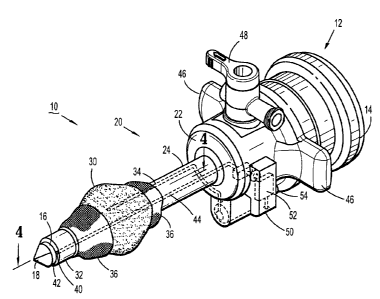
Referring initially to FIGS. 1-3, there is disclosed a safety trocar assembly
10 for use in
surgical procedures. Safety trocar assembly 10 is designed to prevent
overpenetration through
the abdominal wall and thus prevent damage to underlying organs. Safety trocar
assembly 10
includes an obturator 12 having a handle 14 and an elongate shaft 16 extending
distally from
handle 14. Elongate shaft 16 terminates in a tissue penetrating tip 18 which
is provided to
puncture through an abdominal wall. Safety trocar assembly 10 further includes
an airbag
cannula 20 configured to receive obturator 12 therethrough. Airbag cannula 20
generally
includes a housing 22 having a hollow, elongate tubular member 24 extending
distally from
housing 22. A throughbore 26 extends through housing 22 and is in
communication with a
lumen 28 extending through elongate tubular member 24. In the assembled
condition, obturator
12 extends through throughbore 26 and lumen 28 of airbag cannula 20.
Referring for the moment to FIG. 1, airbag cannula 20 includes an expandable
member in
the form of a balloon or airbag 30 positioned on an outer surface 32 of
elongate tubular member
-8-
CA 02686569 2009-11-26
24. Airbag 30 is formed of a flexible, non-expansible material. An inflation
lumen 34 extends
through elongate tubular member 24 and is in fluid communication with airbag
30. Upon
penetration of an abdominal wall, an inflation fluid is forced through
inflation lumen 34 and into
airbag 30 to move airbag 30 from a deflated to an inflated condition as
described in more detail
hereinbelow.
Referring back to FIGS. 1-3, an outer sheath 36 is provided to restrain airbag
30 in the
deflated condition. Outer sheath 36 is affixed to outer surface 32 of elongate
tubular member 24.
A separable perforation line 38 extends around outer sheath 36. Upon inflation
of airbag 30, the
pressure of airbag 30 forces perforation line 38 to separate thereby releasing
airbag 30 to expand
to the inflated condition.
As noted hereinabove, safety trocar assembly 10 is configured to avoid
overpenetration
of the abdominal wall. A sensor opening 40 is provided in a distal face 42 of
elongate tubular
member 24. A sensor lumen 44 extends proximally from sensor opening 40,
through elongate
tubular member 24, and terminates within housing 22. In order to manipulate
housing 22
relative to an abdominal wall, housing 22 is provided with a pair of housing
wings 46.
Additionally, a source of inflation fluid 48 is provided on housing 22 to
transmit insufflation
fluid through lumen 28 in elongate tubular member 24 in order to insufflate a
body cavity to
provide a working space for a surgical procedure.
In order to expand airbag 30 from the deflated to the inflated condition upon
penetration
of safety trocar assembly 10 through the abdominal wall, a trigger mechanism
50 is located on
housing 22 and is provided to synchronize a change in condition sensed by a
sensor associated
with sensor opening 40 and sensor lumen 44, as described in more detail
hereinbelow, with the
inflation of airbag 30. Trigger mechanism 50 includes a trigger 52 which is
provided to receive a
-9-
I
CA 02686569 2009-11-26
signal from the sensor and operates to send inflation fluid through inflation
lumen 34 and into
airbag 30. A control knob 54 is provided to adjust the sensitivity of trigger
52.
With specific reference to FIGS. 2 and 5, trigger mechanism 50 includes a
valve 56
which controls the flow of fluid into airbag 30. Valve 56 is connected to
inflation lumen 34 by
an inflation hose 58. In this embodiment, the particular sensor is an air
pressure sensor 60
positioned within housing 22 and in fluid communication with a proximal end 62
of sensor
lumen 44. Air pressure sensor 60 is provided to detect changes in air pressure
within sensor
lumen 44. Specifically, when distal face 42 of elongate tubular member 24 is
positioned against
tissue, air pressure sensor 60 pressurizes sensor lumen 44 with a
predetermined amount of air
pressure. Sensor opening 40, being positioned on distal face 42 of elongate
tubular member 24,
seals the distal end of sensor lumen 44 against the tissue in the manner
described in more detail
hereinbelow.
Trigger mechanism 50 may be formed as an integral part of housing 22 of
cannula 20 or,
as shown, may be formed as a detachable component. Air pressure sensor 60
includes a port 64
which is engageable with a connector 66 on trigger mechanism 50. Trigger 52 is
connected to,
and operates, valve 56 by a control hose 68. Thus, changes in air pressure
detected by air
pressure sensor 60 are communicated to trigger 52 which in turn operates to
actuate valve 56.
Referring now to FIGS. 4 and 5, inflation hose 58 is connected to a proximal
port 70 of
inflation lumen 34 (FIG. 5) and a distal port 72 of inflation lumen 34 is in
fluid communication
with an interior 74 of airbag 30 ( FIG. 4). As shown, passage of a fluid such
as, for example, a
gas, through inflation lumen 34 and out of distal port 72 moves airbag 30 from
the deflated
condition (FIG. 3) to the inflated condition as shown in FIG. 4.
-10-
CA 02686569 2009-11-26
With continued reference to FIG. 4, proximal and distal ends 76 and 78,
respectively, of
airbag 30 are secured to outer surface 32 of elongate tubular member 24 by
gluing, welding, heat
sealing or shrinking, etc. or other known methods of securing a flexible
material to a substrate.
Similarly, proximal and distal ends 80 and 82, respectively, of outer sheath
36 are secured to
outer surface 32 of elongate tubular member 24.
Referring to FIG. 5, it should be noted that inflation lumen 34 is formed
within the wall
84 of elongate tubular member 24. Similarly, with reference to FIG. 5a, sensor
lumen 44 is also
formed within wall 84 of elongate tubular member 24. Airbag 30 along with
outer sheath 36 are
located at a position proximal of distal end 86 of elongate tubular member 24.
It should be
further noted that, while sensor opening 40 is located at distal face 42 of
elongate tubular
member 24, sensor opening 40 may be provided at other locations on distal end
86 of elongate
tubular member 24 such as, for example, a side of distal end 86 of elongate
tubular member 24,
etc. so long as sensor opening 40 is distal of airbag 30 and outer sheath 36.
Referring now to FIG. 6, there is disclosed an alternative embodiment of a
safety trocar
assembly 90. Safety trocar assembly 90 is similar to safety trocar assembly 10
described
hereinabove and while not specifically shown here includes obturator 12.
Safety trocar assembly
90 additionally includes an airbag cannula 100 having a housing 102 and an
elongate tubular
member 104 extending distally from housing 102. A throughbore 106 extends
through housing
102 and a lumen 108 extends through elongate tubular member 104. An airbag 110
is provided
on an outer surface 112 of elongate tubular member 104. Airbag 110 is
substantially similar to
airbag 30 described hereinabove. An inflation lumen 114 is formed within
elongate tubular
member 104 and includes a proximal port 116 and a distal end port 118 which is
in fluid
communication with airbag 110.
-11-
i
CA 02686569 2009-11-26
Similar to safety trocar assembly 10 described hereinabove, safety trocar
assembly 90
includes a trigger mechanism 120 including a trigger 122 having an adjustable
control knob 124.
A valve 126 is included in trigger mechanism 120 and is connected to trigger
122 by a control
hose 128. An inflation hose 130 extends between valve 126 and proximal port
116 to provide a
source of inflation fluid to airbag 110.
Airbag cannula 110 includes an alternative sensing mechanism for detecting
penetration
of an abdominal wall. Specifically, an electrical sensor 132 is provided and
includes a port 134
for engagement with a connector 136 of trigger mechanism 120. Electrical
sensor 132 detects
the change in resistance between that provided by the abdominal wall and the
interior of the body
cavity after safety trocar assembly 90 has penetrated the abdominal wall.
First and second sensor
wires 138 and 140, respectively, are provided in elongate tubular member 104.
First and second
sensor wires 138 and 140 may extend through a sensor lumen similar to sensor
lumen 44
described hereinabove with respect to safety trocar assembly 10. In the
presently disclosed
embodiment, first and second sensor wires 138 and 140 are embedded within
elongate tubular
member 104. First and second sensor wires 138 and 140 terminate in first and
second wire distal
ends 142 and 144 which are spaced apart from one another. First and second
sensor wires 138
and 140 extend through a distal end 146 of elongate tubular member 104 and are
exposed
through a distal face 148 of elongate tubular member 104.
Referring now to FIG. 6a, first and second sensor wires 138 and 140 are
embedded in a
side wall 150 of elongate tubular member 104. As distal ends 142 and 144 of
first and second
sensor wires 138 and 140 are placed in contact with the abdominal wall, sensor
132, and thus
first and second sensor wires 138 and 140, is energized and detects a specific
amount of
resistance between distal ends 144 and 142. As distal end 146 of elongate
tubular member 104
-12-
I
CA 02686569 2009-11-26
penetrates the abdominal wall and enters the body cavity, the resistance
between distal ends 144
and 142 changes. This change in resistance is detected by sensor 132 which
then signals trigger
124 to actuate valve 126 thereby inflating air bag 110. Similar to airbag
cannula 20 described
hereinabove, airbag cannula 100 includes an outer sheath 152 which surrounds
airbag 110.
Outer sheath 152 includes a separable perforation line (not shown) similar to
perforation line 38
in outer sheath 36 described hereinabove.
Referring now to FIGS. 7 and 7a, it will be appreciated that airbag cannula
20, described
hereinabove, may be provided with a variety of other types of sensors in
housing 22 and which
extended through sensor lumen 44 to sensor opening 40. Examples of such
sensors include
ultrasound sensors, sonar sensors, etc. As shown in FIGS. 7, airbag cannula 20
may be provided
with an optical sensor 160 having a sensor fiber 162 extending distally from
optical sensor 160
through sensor lumen 144. Sensor fiber 162 has a proximal end 164 connected to
optical sensor
160 and a distal end 166 which is positioned within sensor opening 40 at
distal end 86 of
elongate tubular member 24. Sensor 160 includes a port 168 for receipt of
connector 66 of
trigger mechanism 50.
In use, when distal end 86 of elongate tubular member 24 is in engagement with
an
abdominal wall, distal end 166 of optical fiber 162 receives a first amount of
light or a first
image. After distal end 86 passes through the abdominal wall into the
abdominal cavity, distal
end 166 of optical fiber 162 detects a second amount of light or second image
different from the
first amount of light or first image. This difference is communicated through
optical fiber 162 to
optical sensor 160 which then signals trigger 52 to actuate valve 56 thereby
inflating airbag 30.
Thus, as distal end 86 of elongate tubular member 24 penetrates the abdominal
wall, optical
sensor 160 in combination with trigger mechanism 50 operate to instantaneously
inflate airbag
-13-
I
CA 02686569 2009-11-26
30 thereby preventing any further advancement of elongate tubular member 24
through the
abdominal wall. In this manner, underlying organs are protected from
engagement with tissue
penetrating tip 18 of obturator 12 and distal end 86 of airbag cannula 20.
Referring now to FIG. 8, safety trocar assembly 10 is disclosed with an
alternative airbag
170. Safety trocar assembly 10 includes obturator 12 and airbag cannula 20
substantially as
described hereinabove. As shown, airbag 170 forms a generally elongate
doughnut shape around
elongate tubular member 24. Similar to those embodiments described hereinabove
an outer
sheath 172 having a perforation line 174 surrounds airbag 170. In contrast to
airbag 30 described
hereinabove, distal and proximal ends 176 and 178 of airbag 170 are recurved
inwardly and
affixed to outer surface 32 of elongate tubular member 24 by welding, gluing,
heat shrinking,
etc. Likewise, distal and proximal ends 180 and 182 of outer sheath 172 are
also recurved
inwardly and secured against outer surface 32 of elongate tubular member 24.
With specific reference to FIG. 9, upon inflation of airbag 170, a distal end
surface 184 of
airbag 170 projects distally beyond distal end 176 of airbag 170 to provided a
"bumper" for
engagement with the abdominal wall to thereby limit any further advancement of
elongate
tubular member 24 through the abdominal wall.
Referring now to FIGS. 10-12, and initially with regard to FIGS. 10 and 11,
safety trocar
assembly 10 is illustrated with a further alternative embodiment of an airbag
190. Safety trocar
assembly 10 is substantially identical to that described hereinabove including
obturator 12 and
airbag cannula 20. Airbag cannula 20 includes housing 22 having elongate
tubular member 24
extending distally therefrom. Trigger mechanism 50 along with sensor 60 are
provided to inflate
airbag 190 after elongate tubular member 24 penetrates abdominal wall.
-14-
I
CA 02686569 2009-11-26
Airbag 190 includes a proximal end 192 which is secured to outer surface32 of
elongate
tubular member 24 in a manner described hereinabove. An outer sheath 194
surrounds airbag
190 in the undeployed position and includes a proximal end 196 which may be
secured to outer
surface 32 of elongate tubular member 24 or, alternatively, may be secured to
proximal end 192
of airbag 190. In this embodiment, airbag 190 is configured to move distally
along elongate
tubular member 24 upon inflation to engage an abdominal wall. Specifically, a
slide ring 198 is
provided around elongate tubular member 24 and is longitudinally movable along
elongate
tubular member 24 from a proximal position wherein airbag 190 is in the
deflated or undeployed
condition to a distal position wherein airbag 190 is in the inflated
condition. An O-ring 200 is
provided between slide ring 198 and outer surface 32 of elongate tubular
member 24 to seal
airbag 190 against elongate tubular member 24. A distal end 202 of airbag 190
is secured to
slide ring 198. A distal end 204 of outer sheath 194 may be temporarily
secured to slide ring 198
and separates from slide ring 198 upon inflation of airbag 190.
Referring out of FIG. 12, upon forcing inflation fluid through inflation lumen
34 and out
port 70 into an interior 206 of airbag 190, distal and 204 of outer sheath 194
separates from slide
ring 198 and slide ring 198 moves distally along outer surface 32 of elongate
tubular member 24
in response to the inflation of airbag 190. In this manner, advancement of
elongate tubular
member 204 through an abdominal wall proceeds until distal end 202 of airbag
190 engages the
abdominal wall.
Referring now to FIGS. 13 and 14, and initially with regard to FIG. 13, safety
trocar
assembly 10 including obturator 12 and airbag cannula 20 is illustrated with
multiple airbags
210, 212 and 214 located on outer surface 32 of elongate tubular member 24. An
outer sheath
216 is provided to secure airbags 210, 212 and 214 against elongate tubular
member 24 prior to
-15-
I
CA 02686569 2009-11-26
inflation. As best shown in figure 14, recurved side edges 218 and 220 of
airbag 210 are secured
to outer surface 32 of elongate tubular member 24. Likewise, recurved side
edges 222 and 224
and 226 and 228 of airbags 212 and 214 are similarly secured to outer surface
32 of elongate
tubular member 24. Elongate tubular member 24 is formed with multiple
inflation lumens
terminating in inflation ports 230, 232 and 234 which are in fluid
communication with airbags
210, 212 and 214 respectively. The provision of multiple airbags on safety
trocar assembly 10
allows a surgeon to better view the incision in the abdominal wall as elongate
tubular member 24
advances therethrough.
Referring now to FIGS. 15 and 16, and initially with regard to FIG. 15, safety
trocar
assembly 10 is substantially as described hereinabove including obturator 12
and airbag cannula
20. Like those embodiments described hereinabove, airbag cannula 20 includes
air pressure
sensor 60 and trigger mechanism 50 to cause inflation of the disclosed airbags
upon penetration
of an abdominal wall by distal end 86 of elongate tubular member 24. While the
discussions
here in are given in terns of distal end 86 of elongate tubular member 24
penetrating the
abdominal wall, it will be appreciated that trocar assembly 10 as a whole is
advanced against the
abdominal wall such that tissue penetrating tip 18 of obturator 12 causes the
penetration and
informs the incision through the abdominal wall. Distal end 86 of airbag
cannula 20 follows
tissue penetrating tip 18 through the incision.
In this embodiment, as best shown in FIG. 16, a plurality of relatively small
airbags such
as, for example, airbag 240, airbag 242 and airbag 244 are formed about the
circumference of
elongate tubular member 24. Specifically, circumferential edges 248, 250 and
252 of airbags
240, 242 and 244, respectively, are fixed to outer surface 32 of elongate
tubular member 24.
Elongate tubular member 24 is provided with a plurality of longitudinally
extending inflation
-16-
I
CA 02686569 2009-11-26
lumens which terminate in inflation ports 254, 256 and 258 which are in fluid
communication
with airbags 240, 242 and 244 respectively. Similar to those embodiments
described
hereinabove, upon inflation of airbags 240, 242 and 244, outer sheath 246
separates to expose the
airbags. Similar to the embodiments disclosed hereinabove, airbags 240, 242
and 244 are
located proximal of distal end 86 of elongate tubular member 24.
Referring now to FIGS. 17-19, and initially with regard to FIG. 17, the use of
safety
trocar assembly 10, including airbag cannula 20, air pressure sensor 60 and
airbag 30, to
penetrate abdominal wall will now be described. Initially, obturator 12 is
inserted through airbag
cannula 20 such that tissue penetrating tip 18 extends beyond distal end 86 of
elongate tubular
member 24. Airbag 30 is in a deflated condition and is restrained against
elongate tubular
member 24 by outer sheath 36. Safety trocar assembly 10 is advanced against an
abdominal wall
AW such that tissue penetrating tip 18 begins to penetrate or incise abdominal
wall AW. As
discussed hereinabove, safety trocar assembly 10 is provided to penetrate
abdominal wall AW so
as to position distal end 86 of airbag cannula 20 within a body cavity BC
underlying abdominal
wall AW without danger of damaging an underlying organ UO by tissue
penetrating tip 18 of
obturator 12 or distal end 86 of airbag cannula 20.
Referring now to FIG. 18, as tissue penetrating tip 18 of obturator 12 and
distal end 86 of
airbag cannula 20 are advanced into engagement with abdominal wall AW, sensor
opening 40 is
sealed against abdominal wall AW. Air pressure sensor 60 is activated to
pressurize sensor
lumen 44. Air pressure sensor 60 detects and maintains a predetermined amount
of air pressure
within sensor lumen 44. As shown, underlying organ UO is spaced a distance D1
from
abdominal wall AW. Thus, it is necessary to insert tissue penetrating tip 18 a
distance less than
-17-
I
CA 02686569 2009-11-26
distance D1 into body cavity BC. This is accomplished by inflating airbag 30
upon penetration
of abdominal wall AW by tissue penetrating tip 18 of obturator 12.
Referring to FIG. 19, as tissue penetrating tip 18 of obturator 12 and distal
end 86 of
airbag cannula 20 penetrate through abdominal wall AW and into body cavity BC,
sensor
opening 40 in distal face 42 of airbag cannula 20 is exposed or open to body
cavity BC. Because
body cavity BC has a pressure less than the pressure maintained in sensor
lumen 44, the pressure
in sensor lumen 44 drops. Sensor 60 detects the immediate change in pressure
within sensor
lumen 44 and signals trigger 52 of trigger mechanism 50. In response thereto,
trigger 52 actuates
valve 56 to cause inflation fluid to flow through inflation hose 58 and into
inflation lumen 34.
The inflation fluid passes through inflation port 72 into interior 74 of
airbag 30 causing airbag 30
to rapidly expand. As airbag 30 expands, perforation line 38 of outer sheath
32 separates to
release airbag 30 from the restrained condition. The rapid expansion of airbag
30 which, as
noted hereinabove, is positioned adjacent to distal end 86 of elongate tubular
member 24 acts as
a stop or bumper to prevent further advancement of elongate tubular member 24
and tissue
penetrating tip 18 of obturator 12 into body cavity BC. Thus, tissue
penetrating tip 18 of
obturator 12 is restrained a distance D2 from underlying organ UO to prevent
any damage to
underlying organ UO.
It will be understood that various modifications may be made to the
embodiments
disclosed herein. For example, the disclosed airbags may be inflated manually
by manually
operating the valve of the trigger mechanism. Additionally, other forms of
expandable members
such as, for example, movable rigid stops, flexible wings, etc. may be
provided and actuated by
sensors to prevent overpenetration of an abdominal wall by tissue penetrating
tip of an obturator.
Further, other types of sensors may be provided to detect changes in
conditions at the distal end
-18-
CA 02686569 2009-11-26
of the cannula such as, for example, fluid pressure sensors, heat sensors,
physical pressure
sensors, mechanical devices such as movable rods within the sensor lumen etc.
Additionally, the
disclosed sensor detection mechanisms may be incorporated in other surgical
instruments
wherein proper positioning of distal ends of the surgical instruments may be
detected by changes
in conditions encountered by the distal ends of the surgical instruments.
Still further, the
disclosed airbag cannulas and sensors may be used in conjunction with known
safety shields or
penetrating tip retraction devices. Therefore, the above description should
not be construed as
limiting, but merely as exemplifications of particular embodiments. Those
skilled in the art will
envision other modifications within the scope and spirit of the claims
appended hereto.
For example, while the various embodiments described and illustrated herein
have the airbag 30
attached to an outer circumferential surface located near to the distal end of
the cannula, it is also
contemplated that the airbag may be located at any longitudinal position along
the outer circumferential
surface of the cannula. This position may reflect any one or more of various
factors, such as the
thickness of tissue to be penetrated, different internal distances D1,
different types of tissue, and/or
different thrust forces applied by the user. Still further, the length of the
cannula may play a role in the
appropriate position of the airbag 30 thereon.
Furthermore, while the various embodiments described and illustrated herein
have the airbag 30
permanently attached to an outer circumferential surface of the cannula, it is
also contemplated that the
airbag may be selectively and/or adjustably attached to the outer
circumferential surface of the cannula.
In this manner, a user may adjust the position of the airbag 30 so as to
accommodate different thickness of
tissue (e.g., an obese patient may have a thicker tissue wall as compared to a
thin patient), different
internal distances Dl (e.g., a surgical procedure that involves insufflating
an abdominal cavity may have
an internal distance that is greater than a surgical procedure that does not
involve insulating the cavity),
-19-
I
CA 02686569 2009-11-26
different types of tissue (e.g., a patient that has substantial scar tissue
might require different penetrative
forces as compared to a patient that has no such scarring) and/or different
thrust forces applied by the user
(e.g., a male surgeon may employ greater thrust forces as compared to a female
surgeon).
The user of such a selectively and/or adjustably attachable airbag 30 might
determine a position
of the airbag prior to using the trocar and then leave the airbag 30 in that
position for the duration of the
surgical procedure. Alternatively a user might selectively adjust the position
of the airbag 30 one or
more times while actually using the trocar. For example, if a user selects a
first position of the airbag 30
prior to a surgical procedure and then determines, after attempting to
penetrate the abdominal wall AW,
that the selected first position was too close to the distal end of the
cannula (e.g., such that the airbag 30
prevents the tissue penetrating tip 18 from fully penetrating the tissue of
the abdominal wall AW), the
user may then select to adjust the position of the airbag 30 to a slightly
more proximal position prior to
continuing with the penetration of the abdominal wall AW. Still further, the
user might elect to remove
the airbag 30 entirely, at any point of the surgical procedure, if desired.
Still further, while the various embodiments described and illustrated herein
have the airbag 30
attached to an outer circumferential surface of the cannula, it is also
contemplated that the airbag may be
attached to any component of the trocar. For example, the airbag 30 may be
attached to the distal face
of the housing 22. Of course, whatever component the airbag 30 is attached to,
it is desirable that, when
deployed, the airbag 30 is positioned so as to prevent over-penetration of the
trocar through the abdominal
wall AW and to avoid contact by the tissue penetrating tip 18 with the
underlying tissues, e.g.,
internal organs.
-20-
I