Note: Descriptions are shown in the official language in which they were submitted.
CA 02686775 2009-11-06
WO 2008/147303 PCT/SE2008/050548
1
Hydraulic valve device
TECHNICAL FIELD OF THE INVENTION
The invention relates to a hydraulic valve device and is described by
way of examples with particular reference to its application on hydrauli-
cally driven and manoeuvred lifting booms, which are common in many
mobile machines such as e.g. wheel-loaders and digging machines.
BACKGROUND
Many mobile machines include a lifting boom that may be swung up
and down by means of a double acting hydraulic lift cylinder that acts
between the lifting boom and frame work or base of the machine. This
particular lift cylinder is included in a hydraulic system comprising a
hydraulic pump and a hand valve, by means of which the pump may be
connected to the first lift cylinder chamber when the boom is to be ele-
vated and to the second lift cylinder chamber when the boom is to be
sunk. Simultaneously, in the first case the second lift cylinder chamber,
and in the second case the first lift cylinder chamber is, via the hand
valve, connected to a tank for the hydraulic fluid.
Thus, in the most basic embodiment, the hydraulic valve device is such
arranged that the pump fills the first lift cylinder chamber when the
boom is to be elevated or sunk, such that the hydraulic fluid that is
pressed out from the other lift cylinder chamber is released to the tank.
Depending on if the boom is moved with or against the load, the pump
will have to work much or less in order to achieve the necessary pres-
sure for the operation. However, it must always deliver a sufficient flow
to fill the emptying lift cylinder chamber in a pace that allows movement
of the boom in the speed desired by the operator.
CA 02686775 2015-01-05
,
2
An unsatisfactory problem of an arrangement of the described type is that
it makes the efficiency of the hydraulic system low at lowering of a load
since the pump delivers pressure and flow even though the boom could be
sunk by means of its own weight and load.
OBJECT OF THE INVENTION
An object of the present invention is to find a solution to these problems
and provide a valve device that saves a substantial part of the energy that
is lost at lowering of a load with conventional hydraulic load control valves
of the type described above.
This may be achieved in accordance with a first aspect of the invention by
means of a hydraulic valve device comprising:
a first engine port and a second engine port to a double acting
hydraulic motor;
a tank;
a pump;
a hand valve arranged such that it connects the engine ports to the
tank and the pump, and which hand valve has two open positions,
wherein in the first open position the pump is connected to the first engine
port via a first line and the tank is connected to the second engine port via
a second line, and wherein in the second open position the pump is
connected to the second engine port via the second line and the tank is
connected to the first engine port via the first line;
a first nonreturn valve arranged between the pump and the second
engine port and that opens towards the second engine port;
a piston, which by means of a load pressure in the first engine port
via a third line governs the first nonreturn valve, such that it is kept
closed
as long as a pump pressure of the pump does not exceed said load
pressure; and
a second nonreturn valve arranged such that it, as long as the hand
valve is in its first open position, connects the first engine port to the
second engine port and opens in direction towards the second engine port.
CA 02686775 2009-11-06
WO 2008/147303
PCT/SE2008/050548
3
Due to this valve device the hydraulic fluid from the first engine port
will, when the pressure at it is sufficiently high, refill the second engine
port, such that the pump does not have to work in order to lower a load.
In advantageous embodiments of the invention the valve device is ar-
ranged such that refilling may be achieved in both directions, which is
advantageous for machines where the load may act in two directions.
The invention is described in detail below, with reference to the accom-
panying drawings.
SHORT DESCRIPTION OF THE DRAWINGS
Fig. 1 shows a vehicle with a hydraulically manoeuvred boom and a hy-
draulic system with a double acting hydraulic lift cylinder and a con-
ventional valve device mounted thereon;
Fig. 2 is a hydraulic diagram for the lift cylinder in fig. 1, provided with
a conventional valve device;
Fig. 3 is a hydraulic diagram resembling the one in fig. 2, but showing a
valve device in accordance with a first embodiment of the invention;
Fig. 4 is a hydraulic diagram showing a valve device in accordance with
a second embodiment of the invention;
Fig. 5 is a hydraulic diagram showing a valve device in accordance with
a third embodiment of the invention; and
Fig. 6 is a hydraulic diagram showing a valve device in accordance with
a fourth embodiment of the invention.
DETAILED DESCRIPTION OF THE FIGURES
The hydraulically manoeuvred lifting boom shown in fig. 1 is adapted to
be arranged on a vehicle (not shown) and has a base A with a rotatable
CA 02686775 2009-11-06
WO 2008/147303 PCT/SE2008/050548
4
crane B, which carries the boom arm C at its upper end. A double act-
ing hydraulic motor, in form of a hydraulic lift cylinder D is arranged
between the boom arm C and the foot of the crane B of the base. Lines
F and G connect the two lift cylinder chambers to a hand valve H, which
in the shown example is lever controlled and in turn is connected to a
hydraulic pump and a tank T via additional lines J and K, respectively.
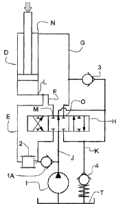
In fig. 2, a part of the hydraulic system of the machine, which is useful
to manoeuvre the lift cylinder D, is shown. The first, lower, chamber of
the lift cylinder (the lifting chamber), has a first engine port, hereafter
called the lower lift cylinder port L, as the lift cylinder D constitutes the
motor. The line F connects the lift cylinder port to a first feed connec-
tion port or operational port M on the hand valve H, which in the shown
example is of an open centre type. The second, upper chamber of the lift
cylinder (the release chamber) correspondingly has a second engine
port, called upper lift cylinder port N, which is connected to a second
operational port 0 on the hand valve H, via the line G. When the hand
valve is in the position shown in the figure, the pump flow flows
through the centre line of the hand valve to the line K and on to the
tank T.
The fluid flows through the valve back to the tank with a very low pump
pressure why very little energy is consumed. However, as long as the
motor is running it is common procedure to let the pump work and it is
thus not expected to turn off the pump I just because there is no in-
stantaneous need to change the position of the boom.
As soon as the hand valve is manoeuvred in any direction, the centre
line will be partly closed and the pump I will be connected to one of the
chambers of the lift cylinder, whereby the second chamber of the lift cyl-
inder to a correspondingly degree will be connected to the tank T. If the
pressure delivered by the pump is sufficiently high, a certain flow will
flow through the hand valve to the connected lift cylinder chamber at
CA 02686775 2009-11-06
WO 2008/147303
PCT/SE2008/050548
the same time as the other lift cylinder chamber to a correspondingly
degree is emptied to the tank T, whereby the boom will be moved.
When the boom C is raised (raising of a positive load) the hand valve H
directs the hydraulic fluid under high pressure from the pump through
5 the first operational port M and the line F to the lower chamber of the
lift cylinder D. Since the pump pressure must act against the load in
this instance in order to open the nonreturn valve 1, the pump pressure
must be controlled to a relatively high level, i.e. sufficiently high so that
the pressure in the line J exceeds the pressure in the lower chamber of
the lift cylinder D and thus the line F, before the pump flow will fill the
lower chamber of the lift cylinder D. Thus, on manoeuvring of the hand
valve H, the opening of the centre line is reduced, whereby the pump
pressure increases. At the same time the valve opens from the feed con-
nection port M to the lower cylinder port L and from the upper cylinder
port N to the tank connection 0 of the valve. When the valve is manoeu-
vred such that the pump pressure exceeds the pressure in the cylinder
port, the nonreturn valve 1 opens and a flow from the pump to the cyl-
inder is released. Upon further manoeuvring of the valve the flow
through the valve to the cylinder increases. Hydraulic fluid will at the
same time under low pressure flow through the line G and the hand
valve H to the tank T.
The nonreturn valve 1 in the feed line J of the valve H prevents flow "in
the wrong direction", opposite the pump flow, upon activation of the
valve and when the pump pressure is lower than the pressure in the
port of the cylinder, which otherwise would constitute a great danger.
When the boom C is lowered (lowering of a positive load) the hydraulic
fluid from the pump is directed through the second operational port 0
of the hand valve H to the upper chamber in the lift cylinder D, and the
hydraulic fluid from the lower lift cylinder chamber is directed to the
tank T.
CA 02686775 2009-11-06
WO 2008/147303 PCT/SE2008/050548
6
On command the valve between the lower cylinder port L and the tank T
opens, resulting in that the cylinder is moved downwards in the figure.
Simultaneously the centre line is closed and the pump pressure in-
creases, wherein a flow from the pump to the suction side of the cylin-
der, i.e. the upper cylinder port N, is provided. The pump flow at a low-
ering movement involves a loss of energy, which is a disadvantage of
this system.
An automatic restriction of the energy loss created in the system in fig-
ure 2 may be achieved by means of an automatic low pressure regen-
eration in accordance with the invention. The valve device according to
the invention represents a substantial improvement with respect to the
efficiency loss compared to the prior art, as represented in fig. 1 and 2.
Four exemplifying embodiments of the invention are shown in fig. 3, 4,
5 and 6.
The representation of the diagram of figure 3 differs from figure 2 in
that the nonreturn valve lA is complemented with a piston 2, which is
governed by the load pressure in the lower lift cylinder port L. Further,
a nonretum valve 3 is arranged and connects the centre line and the
line K leading to the tank T to the upper lift cylinder port N. The nonre-
turn valve 3 opens towards the upper lift cylinder port N and closes to-
wards the centre line. Additionally, on the line K, a back-pressure valve
or a pre-stressed nonretum valve 4 may be arranged to open towards
the tank T, at a certain pressure. The nonretum valve 4 is mainly in-
tended to create a certain resistance for the hydraulic fluid towards the
tank T, but as there often exits a certain inherent resistance in the lines
towards the tank, this nonretum valve 4 is not always needed.
At lowering of the cylinder piston, the valve is manoeuvred such that a
flow from the lower lift cylinder port L, which is subjected to a load, to
the tank is obtained, which results in a sinking movement of the cylin-
der piston. At the same time, the pump flow is prevented from flowing to
CA 02686775 2009-11-06
WO 2008/147303
PCT/SE2008/050548
7
the suction side of the cylinder, i.e. the upper lift cylinder port N due to
that the load pressure at the lower lift cylinder port L via the piston 2
keeps the nonreturn valve lA in a closed position. Instead, the suction
side of the cylinder is refilled via the nonretum valve 3, which redirects
the flow from the pressure side of the cylinder, i.e. the lower lift cylinder
port L, to its suction side, via the tank line G. The back-pressure valve 4
in the tank line makes sure that the outlet flow from the pressure side
of the cylinder in the first event flows to the suction side of the cylinder.
However, since the lower cylinder has a greater volume than the upper
cylinder a certain flow flows through the back-pressure valve 4 to the
tank T.
The back-pressure valve 4 may be adapted for a low pressure e.g. 3 Bar,
which does not provide an efficiency loss of importance upon raising of
a load.
If the load, turns into a lifting load while the cylinder piston is being lo-
wered, such that the upper chamber and hence the port N of the lift cyl-
inder becomes put under pressure, the pressure acting on the piston 2
will cease, whereupon the nonretum valve lA automatically will open
such that the pump may direct the pump flow to the port N of the upper
cylinder chamber. Thus, the upper cylinder chamber may be filled re-
gardless of if the load that acts on the cylinder is positive or negative,
but when the load is positive the piston 2 will keep the nonretum valve
lA closed, such that the upper cylinder chamber is filled solely with hy-
draulic fluid from the port L of the lower lift cylinder chamber, which is
under pressure. This method is in this application referred to as auto-
matic low pressure regeneration.
If the cylinder is arranged such that it may be exerted to both pressing
and tensioning pressure load, the automatic low pressure regeneration
may be useful in both directions. Such a valve device is shown in figure
4. In this second embodiment of the invention, the device is comple-
CA 02686775 2009-11-06
WO 2008/147303
PCT/SE2008/050548
8
mented by a nonreturn valve 5 from the tank line K to the lower cylin-
der port L and by a reverse valve 7 that directs the highest cylinder port
pressure to the piston 2 of the nonreturn valve IA.
When the cylinder piston is raised, the flow out from the upper cylinder
port N is, due to the ratio between the different cross sections of the cyl-
inder, less than what is needed to fill up the upper lift cylinder port L.
However, a pressure reducing valve 6 adjusted for a lower pressure than
the back-pressure valve 4, is arranged to open when the pressure in the
tank line K goes below a certain pressure such that the pump flow may
flow through the same and guarantee some pressure in the tank line K,
such that cavitation on the suction side of the cylinder is avoided. The
pressure reducing valve 6 is arranged to open at a lower pressure than
the back-pressure valve 4, such that it does not open when there exists
a flow to the tank T.
If it is desired to raise a negative load, i.e. to move the piston rod in the
direction of a load acting upwards, the hand valve H may be manoeu-
vred to a first open position, at which the outlets of the pump I and the
nonreturn valve lA are connected to the first operational port M and
hence to the lower lift cylinder port L. Simultaneously, the upper lift cyl-
inder port N will become connected to the tank line K, via the second
operational port 0, and since the upper cylinder is on load the hydrau-
lic fluid flowing out from the upper lift cylinder port N has a high pres-
sure, such that the pressure reducing valve 6 is initially kept close. Ad-
ditionally, the same pressure will be transmitted from the reverse valve
7 via the line E to the piston 2 of the nonreturn valve IA, such that this
is kept closed. Due to the low pressure at the negatively loaded lower lift
cylinder port L the flow from the upper cylinder port N will flow through
the nonreturn valve 5 to said lower lift cylinder port L. Since the centre
line of the hand valve is throttled the more it is moved towards the first
open position the pressure will decrease in the line K, as a consequence
CA 02686775 2009-11-06
WO 2008/147303
PCT/SE2008/050548
9
of that the hydraulic fluid from the upper cylinder port N is not enough
to fill the lower cylinder, whereby the pressure reducing valve 6 opens,
such that the pump flow may flow under a very low pressure to the line
K and on through the nonreturn valve 5 to the lower the cylinder L,
wherein cavitation in it is avoided in a most energy saving manner.
If, on the contrary and in a corresponding manner, it is desired to sink
a positive load, i.e. to move the piston rod in the direction of a load act-
ing downwards the hand valve H may be manoeuvred to a second open
position, in which the outlets of the pump I and the nonreturn valves
lA is connected to the second operational port O. and hence to the up-
per lift cylinder port N. Simultaneously, the lower lift cylinder port L will
be connected to the tank line K, via the second operational port M, and
since the lower cylinder is on load the hydraulic fluid flows out from it
under high pressure, whereby the pressure reducing valve 6 will be kept
closed. Additionally, the same pressure will be transmitted from the re-
verse valve 7 to the piston 2 of the nonreturn valve IA, via the line E,
such that this is kept closed. The pump flow will thus flow through the
open centre of the hand valve H to the line K under a low pressure. Due
to the low pressure at the negatively loaded lower lift cylinder port L, the
flow will in the first instance flow through the nonreturn valve 5 to said
lift cylinder port L, wherein the surplus flows via the nonreturn valve 4
to the tank T.
Figure 5, shows a valve device resembling the valve device in figure 3,
but in which the nonreturn valve with a piston is placed closer to the
cylinder. The function of the valve device in figure 5 is the same as for
the valve device in figure 3. A reason for arranging two different em-
bodiments having the same functions is that they may present alterna-
tive for different existing hydraulic systems and that one may be advan-
tageous in certain systems, while the other is better suited for other
types of systems. This choice is mainly dependent on whether it is de-
CA 02686775 2009-11-06
WO 2008/147303
PCT/SE2008/050548
sired to keep the components, such as valves and similar, gathered
close to the lift cylinder or not.
In order to replace the function of the nonreturn valve lA with a piston
shown in figure 3, two additional nonreturn valves 8 and 9 are needed
5 to achieve the same function, and a nonreturn valve 1, which corre-
sponds to the nonreturn valve lA in figure 3 and 4 without piston, is
arranged to prevent flow opposite to the pump flow. The nonreturn valve
8, which by means of the piston 2 is governed by the pressure in the
lower cylinder port L, takes the part of all the parts of the nonreturn
10 valve 1A in figure 3, when the feed connection M is connected to the
upper cylinder port N to fill the same. If a load acts downwards on the
cylinder, this nonreturn valve 8 will be kept closed, as result of to the
load pressure towards the piston 2. Thus, the pump flow will flow under
low pressure back to the tank T, while the hydraulic fluid that is al-
lowed to leave the lower cylinder port L towards valve port M and the
line K will refill the upper cylinder chamber via the nonreturn valve 3.
The anti parallel nonreturn valve 9 is necessary in order to allow the
upper cylinder chamber to empty to the tank.
In correspondence with the embodiment shown in figure 3 the embodi-
ment shown in figure 5 only offers automatic low pressure regeneration
in one direction. Therefore, in figure 6 an embodiment that resembles
the embodiment shown in figure 5, but which in correspondence to the
embodiment of figure 4 offers automatic low pressure regeneration in
two directions, is shown.
In the diagram of figure 6, two pistons 2 and 10, and in connection to
these, four nonreturn valves 8, 9 and 11, 12, are arranged, two for each
piston. The piston 2 and the nonreturn valves 8 and 9 are arranged ex-
actly in the same manner as in figure 5, while the piston 2 and the non-
return valves 11 and 12 are arranged in a corresponding manner, ex-
CA 02686775 2009-11-06
WO 2008/147303
PCT/SE2008/050548
11
cept that they control the flow to and from the lower cylinder chamber L
instead of the upper.
Thus, when a negative load is exerted on the cylinder, i.e. when the pis-
ton rod is being loaded from below in the figure, the pressure from the
load will, by means of the piston 10, keep the nonreturn valve 1 I
closed, such that the pump flow instead chooses the path through the
centre line of the hand valve H, via the nonretum valve 4, to the tank T.
The lower cylinder chamber will then be filled primarily with return flow
from the upper cylinder chamber, which flows via the nonretum valve 9
through the hand valve H to the tank line K, where it is added to the
pump flow. Since the nonretum valve 4 is lightly pre-stressed the flow
will primarily be lead through the nonreturn valve 5 to the lower lift cyl-
inder port L.
As mentioned above, the flow from the upper lift cylinder port N is not
enough, due to ratio of the sectional areas, to fill the lower cylinder
chamber, but since the flow from the upper cylinder chamber is com-
pleted with the pump flow, there is no risk for cavitation in the lower
cylinder chamber. Thus, on movement in direction with a negative load,
the pump has to deliver a certain flow in order to avoid cavitation, as
opposed to when the cylinder piston is moved in direction with a posi-
tive load where the return flow from the lower lift cylinder port L is suf-
ficient to alone fill the upper cylinder chamber N.
The invention has been described with reference to four embodiments
with the same particular application. However, it is obvious to a person
skilled in the art that various embodiments and applications are feasi-
ble for the invention, the scope of which is only limited by the following
claims.