Note: Descriptions are shown in the official language in which they were submitted.
CA 02686878 2009-11-09
WO 2008/140575
PCT/US2007/084899
Systems, Components, and Methods for Delivering
Liquid Substances
BACKGROUND
The present disclosure broadly relates to a fluid delivery system and
components
associated therewith. The present disclosure is more particularly directed to
systems,
components and methodologies for the application of liquid chemical
substances, such
as pesticides, to a selected area to be treated.
Farming has evolved significantly over time enabling farmers to increase crop
yield and optimizing both time and agricultural land. Centuries ago, farming
was very
labor intensive and families typically lived on small farms using domesticated
animals
and simple tools to prepare the land and plant crops. The long hours in the
field during
these times generally resulted in low product yields. Over time, horse powered
farming
equipment was replaced by steam powered tractors and ultimately by gasoline
and
diesel powered tractors.
Today, farming can be described as an integrated system of specialized
equipment, science, and computers. The marriage of farming, technology, and
science
has particularly enhanced crop sustainability and improved efficiency and
profitability.
Indeed, the advent of synthetic chemicals has successfully increased crop
yields and it
is estimated that approximately 2.5 million tons of pesticides are currently
used each
year.
The agricultural industry, as a whole, strives to improve its agricultural
products,
farming methodologies, and equipment not only to optimize crop yield, but to
achieve a
suitable balance among a number of variables such as the social,
environmental, and
economic aspects of farming in general. This balance can, arguably, be best
achieved
through the input and interaction of all stakeholders, including the growers,
researchers,
manufacturers, policy makers, farm workers, distributors, retailers and
consumers.
One component of this industry that is realizing its role in creating this
balance is
the agrochemical industry. While it is important for agrochemical companies to
continue
to improve pesticide formulations, it is equally important for these companies
to
recognize that the packaging, transportation, storage, use, and ultimate
disposal of their
products and product containers should also be taken into consideration.
Companies
that strive not to just sell their chemical products, but also facilitate the
use and handling
1
CA 02686878 2009-11-09
WO 2008/140575
PCT/US2007/084899
of the product throughout its lifecycle can add value not only to their
retailers, distributors,
and growers, but also provide a spectrum of environmental, financial, and
social benefits.
To this end, some agrochemical companies have developed and implemented
strategies and programs that reduce the impact of their products on the
environment.
For example, some companies have made substantial advancements in improving
the
integrity of their product packaging and promoting reusable packaging and
recycling
programs to systematically and efficiently refill the containers as incentives
to use these
programs. The advancements made thus far in packaging solutions and efforts to
employ reusable containers appear to be alleviating the environmental impact
of
agrochemical products and other hazardous materials. Some benefits realized,
for
example, include conservation of materials, conservation of landfill space,
and improved
soil and water quality.
Another area in which some agrochemical companies are investing resources is
the development of innovative ways to facilitate and promote precision farming
and
operator safety. Precision farming generally involves the gathering of
information, and
the subsequent analysis of that information to then employ the appropriate
technology to
optimize crop yield. Precision farming oftentimes incorporates a variety of
modern
technological tools including global positioning system, mapping software,
yield monitors,
variable rate technology, and remote sensing equipment. Farm equipment such as
crop
sprayers that incorporate this technology has been developed. Specifically,
crop
sprayers equipped with direct injection systems are currently assisting
farmers in utilizing
precision farming techniques while reducing exposure to pesticides by those
who
operate the equipment.
Crop sprayers equipped with direct injection systems usually include a source
of
a liquid chemical product, such as a pesticide and a separate source of water.
A
metered flow of the pesticide is then injected into a water stream where the
pesticide is
diluted to a specified concentration prior to being sprayed to the area to be
treated. The
injection pumps can be switched on and off as required to spray specified
areas and the
amount of pesticide to be applied can be adjusted depending upon the level of
pest
infestation. Since the pesticide and the water remain separate, the direct
injection
system eliminates the need for a mixing tank, which is common to many crop
sprayers in
use today. Furthermore, some direct injection systems are adapted to be
"closed
transfer systems", which means that the operator does not physically transfer
the
pesticide from its original container to a mixing tank or other tank on the
crop sprayer.
2
CA 02686878 2009-11-09
WO 2008/140575
PCT/US2007/084899
Crop sprayers incorporating this technology are showing increasing promise for
replacing more conventional crop sprayers.
Although the aforementioned improved packaging solutions, recycling efforts,
and development of precision farming technology generate noticeable
environmental,
health, and economic benefits, there continues to be a need to develop
improved
technology to optimize these benefits. Moreover, as precision farming
technology
evolves and begins to replace conventional farming technology, there is a need
for
agrochemical companies to develop improved packaging solutions that safeguard
the
health and safety of those operating the equipment, while facilitating the use
of the
equipment. The present invention is directed to meeting these needs.
SUMMARY OF THE INVENTION
According to the present disclosure, a product reservoir is provided that is
adapted to contain a product to be dispensed to a selected area. The product
reservoir
broadly includes a flexible bag and a carton. The bag has a bag interior for
containing
the product and a spout in communication with the bag interior. The carton has
a
sidewall extending around a carton interior that is sized and adapted to
receive and
retain the flexible bag and has opposing first and second ends.
The carton sidewall is constructed of a plurality of panels including a front
panel
and a back panel in parallel and spaced relation to the front panel. A pair of
opposing
side panels extend between the front and back panels. The carton has a carton
interior
with opposing first and second open ends. The carton is further provided with
first and
second end closures adapted to cover the first and second open ends and
enclose the
carton interior when in a closed state. The first and second ends are formed
from a
plurality of flaps. The first end closure includes a first front flap, a first
back flap, and a
pair of first side flaps, while the second end closure includes a second front
flap, a
second back flap, and a pair of second side flaps. The carton may also be
provided with
a removable spout access panel that extends continuously between a portion of
the first
front flap and a portion of the front panel. Removal of the access panel
reveals or
thereby forms an opening sized and adapted to permit access to the spout and
allow at
least a portion of the spout to extend therethrough.
The carton side panels may have a length that is greater than the length of
both
the front and back panels such that the carton is generally rectangular in
configuration
and formed of a corrugated material. The sidewall panels, the first and second
closure
3
CA 02686878 2009-11-09
WO 2008/140575
PCT/US2007/084899
flaps, and the spout access panel may all be formed as an integral, one-piece
construction of corrugated material.
The spout access panel is preferably accessible when the first and second
closure flaps are in the closed state. To this end, a pair of side closure
flapsmay be
adhered to the front and back panels, and may further be provided with
respective edge
portions that are in spaced relation to one another thereby to form a gap to
permit
access to the panel. The remaining portions of each respective flap edge are
preferably
in confronting relation to one another.
Access panel may further be formed by a series of perforations. The
perforations
are formed in the first front flap and the front panel with sufficient depth
to be easily
punched out or removed to form or thereby expose the spout opening. The
opening
may be described has having two portions ¨ a first portion formed in the first
front flap
and a second portion formed in the front panel. The second portion of the
opening may
be generally U-shaped in configuration and sized and adapted to nestably
receive at
least a portion of the spout therethrough.
With respect to the bag, it may be filled via the spout with a selected liquid
such
as an agricultural chemical. The bag may include a bag wall surrounding the
bag interior
that may be formed of a polyethylene. More particularly, the bag wall may be
formed of
a top panel and a bottom panel joined about their respective peripheries
thereof. Both
the top and bottom panels may be constructed of three sheets of polymer film.
The present disclosure also contemplates a fluid delivery system, wherein the
product reservoir generally described above is incorporated as a component
thereof. As
such, the spout is adapted to be connected to a fluid pathway, which permits
the bag
interior to be in fluid communication with a delivery device such as a
delivery tube,
nozzle, or other device commonly known in the art. This interconnection may be
formed
by a coupler, which couples a conduit to the spout. A water reservoir may also
be
provided that is in fluid communication with the selected delivery device.
More particularly, the product reservoir may be interconnected with a direct
injection system whereby liquid chemical treatment and water are drawn from
their
respective reservoirs, mixed in-line, and applied via the deliver device. As
such, the
present disclosure contemplates both an improvement to a conventional direct
injection
system, as well as agricultural equipment incorporating the same, whereby the
chemical
treatment is applied in a closed transfer system. A plurality of product
reservoirs can be
connected to the direct injection system via an array of conduits or fluid
pathways. In
4
CA 02686878 2015-01-26
, 30469-47
this way, a sufficient volume of liquid chemical treatment may be available
for large-
scale treatment operations. For example, eight product reservoirs, each
containing
approximately 2.5 gallons of liquid chemical treatment can be supported by an
agricultural seed planting machine thereby to accomplish an in-furrow
application of a
selected agricultural product.
The present disclosure also contemplates a method of applying a liquid
pesticide wherein a product reservoir, such as described above, is provided.
The
method includes drawing the liquid chemical treatment from the flexible bag
and
directing the treatment to a delivery device, which applies the treatment to
the
selected area. The method may further include the steps of removing the spout
access panel, extending at least a portion of the spout through the spout
opening,
and attaching a coupler thereto. The coupler is operative to place the bag in
fluid
communication with a delivery device, which forms a component of a direct
injection
system. The method may be used to accomplish in furrow application of a liquid
pesticide wherein a plurality of product reservoirs are supported by a
planting
assembly operative to form a seed furrow and deposit both seeds and liquid
chemical
treatment prior to closing the furrow.
According to one aspect of the present invention, there is provided a
fluid delivery system adapted to dispense a liquid chemical product to a
selected area
for treatment, comprising: a cabinet having at least one pair of stacked bins
and a
door configured to close and cover the at least one pair of stacked bins; a
flexible bag
positioned within one of the stacked bins, wherein the flexible bag has a bag
interior
containing a pesticide, said bag including a spout communicating with the bag
interior; a delivery device in fluid communication with the bag interior and
adapted to
receive and dispense the chemical product to the selected area to be treated;
and a
fluid pathway interconnecting said bag and said delivery device.
According to another aspect of the present invention, there is provided
in an agricultural seed planting machine having a frame, a seed reservoir
containing
seeds supported by said frame, a plurality of row units mounted on said frame
and
5
CA 02686878 2015-01-26
= 30469-47
operative to form a seed furrow and deposit the seeds into and the furrow at a
selected rate, the improvement comprising: (A) at least one cabinet defining a
plurality of bins each for receiving at least one product reservoir, wherein
said at least
one cabinet is supported by said frame; (B) a plurality of product reservoirs
positioned
within said at least one cabinet, wherein each said product reservoir
includes: (1) a
flexible bag having a respective bag interior containing a chemical product to
be
dispensed in the seed furrow; and (B) a carton, including a sidewall
surrounding a
carton interior sized and adapted to receive and retain said flexible bag; (C)
a direct
injection system adapted to connect to said plurality of product reservoirs,
including
(1) a plurality of fluid pathways interconnecting each one of said product
reservoirs
and the row units; (2) a dispensing tube associated with each said row unit
and
operative to receive and dispense the chemical product to the furrow; and (3)
at least
one pump operative to draw the chemical product from said flexible bag to said
tube.
According to still another aspect of the present invention, there is
provided a closed transfer system for the application of agricultural
chemicals to a
selected area, comprising: a cabinet having at least one pair of stacked bins
and a
door configured to close and cover the at least one pair of stacked bins; a
product
reservoir positioned within one of the stacked bins, wherein the product
reservoir
includes (1) a carton having a sidewall surrounding a carton interior, said
sidewall
having an opening formed therethrough; (2) a bag received in the carton
interior
having a bag interior containing an agricultural chemical and a spout
communicating
therewith, and wherein at least a portion of said spout extends through the
opening in
said carton sidewall; a water reservoir containing water; a first fluid
pathway
associated with said product reservoir and a second fluid pathway associated
with
said water reservoir; a mixing chamber in fluid communication with said first
and
second fluid pathways wherein said water dilutes said agricultural chemical to
form a
mixture suitable for the application thereof; and a spray delivery device in
fluid
communication with said mixing chamber and operative to spray said application
mixture to a selected area.
5a
CA 02686878 2015-01-26
30469-47
According to yet another aspect of the present invention, there is
provided a method of applying a liquid pesticide to a selected area from a
delivery
device, comprising the steps of: (A) obtaining a pesticide reservoir, the
reservoir
including: (1) a bag having an interior sized and adapted to contain the
pesticide,
wherein pesticide is positioned within the bag and a spout in communication
with the
pesticide; and (2) a carton adapted to receive said bag and pesticide
contained
therein, wherein the carton includes a spout access panel; (B) opening the
spout
access panel and positioning the spout of the bag therethrough; (C) securing
the
pesticide reservoir within the bin of a cabinet; and (D) directing said
pesticide to the
delivery device through which the pesticide is applied to the selected area.
According to a further aspect of the present invention, there is provided
a method of applying a liquid pesticide to a seed furrow formed by a planting
assembly that is operative to form the seed furrow and deposit a seed therein
and
equipped with a direct injection system, said method comprising: (A)
positioning a
product reservoir within a cabinet mounted on said planting assembly wherein
said
product reservoir includes: (1) a bag having an interior sized and adapted to
contain
the pesticide; and (2) a carton adapted to receive said bag and pesticide
contained
therein; (B) connecting said product reservoir to the direct injection system;
and (C)
directing the pesticide from said product reservoir to a nozzle associated
with the
direct injection system with sufficient force such that the liquid pesticide
is sprayed
into the seed furrow.
BRIEF DESCRIPTION OF THE DRAWINGS
Fig. 1 is a perspective view of a product application system
incorporating two cabinets containing product reservoirs according to the
present
invention;
Fig. 2 is a perspective view of a representative cabinet shown in Fig. 1;
5b
CA 02686878 2015-01-26
. 30469-47
Fig. 3 is a perspective view of the cabinet shown with the cabinet door open
to
reveal the four (4) product reservoirs contained therein;
Fig. 4 is a perspective view of a representative product reservoir shown in
Fig. 3
and the coupling assembly that couples the product reservoir to the direct
injection
system;
Fig. 5 is an exploded perspective view of the product reservoir and coupling
assembly,
Fig. 6 is an exploded perspective view of the carton and flexible packaging
components of the product reservoir,
Fig. 7 is a cross-sectional view of the flexible packaging taken about lines 7-
7 in
Fig. 6;
Fig. 8 is a perspective view of the carton wherein the first and second open
ends
of the carton interior are shown before the closure flaps are folded into the
closed state;
5c
CA 02686878 2009-11-09
WO 2008/140575
PCT/US2007/084899
Fig. 9 is a top plan view of the carton showing the interior wherein the first
closure flaps are folded outwardly, for perspective, and the second closure
flaps are in
the closed state;
Fig. 10 is a top plan view showing a one-piece production blank used to
construct
the carton;
Fig. 11 is a perspective view of the carton showing the glue flap overlying
one of
the panels of the carton;
Fig. 12 is a perspective view of the carton showing a portion of the spout
opening
formed in the front panel;
Fig. 13 is a perspective view of the carton showing the spout access panel
before
it has been removed;
Fig. 14 is a perspective view, partially cut-away, showing the spout extending
through a first portion of the opening wherein the spout has a handled
attached thereto
to facilitate movement of the spout into position;
Fig. 15 is a perspective view, partially cut-away, showing the spout now
nested in
the U-shaped second portion of the opening in the front panel awaiting
connection to the
direct injection system;
Fig. 16 is a perspective view of a carton according to a second embodiment of
the present invention, showing a spout access panel formed in the front panel
prior to
removal;
Fig. 17 is a perspective view of a carton according to a third embodiment of
the
present invention showing a spout opening formed in the front panel having an
elongated U-shaped opening relative to the spout opening shown in Fig. 5; and
Fig. 18 is a perspective view of the carton shown in Fig. 17 with the bag
enclosed
therein and the spout extending through the spout opening.
DETAILED DESCRIPTION OF THE EXEMPLARY EMBODIEMENTS
The exemplary embodiments described herein broadly concerns fluid delivery
systems and components therefore. The fluid delivery system and its components
have
particular utility for the application of liquid chemical substances, such as
liquid
pesticides, fertilizers, and other treatments to a selected area to be
treated. As used
herein, the term "pesticides" broadly encompasses a variety of formulations
tailored to
prevent, destroy, repel, or lessen the damage of a particular pest. There are
several
general categories of pesticides, including herbicides, insecticides,
fungicides, and
rodenticides, to name a few.
6
CA 02686878 2014-04-25
30469-47
The present disclosure more particularly relates to a system for delivering
liquid
pesticide products contained in a pesticide reservoir that generally includes
a flexible
packaging housed within a container or carton, such as a box formed of
corrugated
material. The pesticide reservoir is adapted to connect to a direct injection
system
operative to inject the pesticide from the flexible packaging and into a water
stream prior
to be sprayed through a plurality of nozzles. The present invention is also
directed to a
method of applying liquid agrochemical products.
To better understand this fluid delivery system and its utility, reference is
first
made to Fig. 1, which shows a portion of product application system 10, which
is
operative to both deposit seeds and deliver pesticides. Product application
system 10 is
shown here in the form of a multi-row planter that is adapted to connect to
and be pulled
by a tractor (not shown). Product application system 10 shown here generally
includes
seed reservoir 14, water reservoir 16, and a plurality of spaced apart row
units 18.
Additional reservoirs and planting equipment may also be components of this
system,
however, and the ones shown here are for illustrative purposes.
Each row unit 18 may be constructed, for example, as described in U.S. Patent
No.
6,289,829 B1 , issued on September 18, 2001 to Fish et al. and assigned to
Aventis
CropSceince S.A. (the '829 Patent"). As shown in Fig. 1 and as described in
the '829
Patent, each row unit 18 is operative to form a seed furrow. Seeds received
from a seed
source, such as seed reservoir 14, may be singulated by a conventional seed
meter and
deposited into the furrow via a seed tube, or other device known in the art.
In addition to
depositing the seeds, row units 18 also include a delivery tube, nozzle, or
other appropriate
conventional device that administers a liquid chemical treatment into the
furrow. Depending
upon the structure of the row unit, this treatment can be applied prior to the
seed being
deposited in the furrow, or directly over the top of the seed and therearound
after the seed is
deposited. As product application system 10 continues to move in a forwardly
direction, the
closing wheels close the soil over the seeds. This particular treatment method
is commonly
referred to as "in-furrow treatment" and as should be appreciated by one of
ordinary skill in
the art, any suitable liquid chemical treatments can be applied this way such
as liquid
fertilizers, pesticides, or agricultural additives, to name a few.
As generally described above, the product application system 10 is associated
with a fluid delivery system, which is operative to transfer the liquid
chemical treatment
7
CA 02686878 2009-11-09
WO 2008/140575
PCT/US2007/084899
from a source to a delivery device such as a tube or nozzle. This fluid
delivery system
can be described as a direct injection system, as known in the art. Direct
injection
systems are operative to draw water from a water reservoir thereby to form a
water
stream and liquid chemical treatment from a separate product reservoir. The
chemical
treatment is injected into the water stream and mixed in a mixing chamber or
other inline
device at a location upstream from the delivery device. The mixture thereby
formed is
then dispensed via the delivery device into the furrow.
One such liquid chemical treatment that can be applied in this way is an
insecticide such as Force CS, which is a product provided by Syngenta Crop
Protection, Inc., located in Greensboro, N.C., and the assignee to this
application. The
Force CS product is a pre-emergence insecticide that when applied to seeds as
a seed
treatment, assists in the control of soil pests that can damage or otherwise
destroy
germinating seedlings.
With the above description in mind, then, the components of the fluid delivery
system can be described in more detail. With continued reference to Fig. 1 and
additional reference to Figs. 2 and 3, product application system 10 includes
a plurality
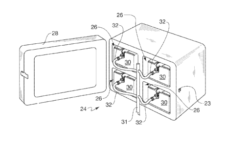
of product reservoirs 30, which are housed in cabinets 20 and 22. Since
cabinets 20
and 22 are identical in structure, a representative cabinet 20 will be
discussed in more
detail. As best shown in Fig. 3, cabinet 20 has an interior 24 that is divided
into four
bays 26. Each bay 26 is sized and adapted to receive a single product
reservoir 30
therein. Cabinet 20 includes door 28 associated therewith that when open,
permits
access to the interior 24 as shown in Fig 3. Door 28 can be closed to conceal
the
interior, as shown in Fig. 2 and a conventional latching device 23 can be used
to keep
the door closed. With continued reference to Fig. 3, product reservoirs 30 are
associated with an array of fluid pathways shown here in the form of conduits
31 and 32,
which are adapted to interconnect product reservoirs 30 to the direct
injection system.
As shown, each product reservoir is directly connected to conduit 32, which is
connected
to or otherwise feeds into one central conduit 31. Central conduit line 31
extends
underneath cabinet 20 and is adapted to connect to the direct injection system
thereby
placing each product reservoir 30 in fluid communication with both the in-line
mixing
chamber and delivery device. As should be appreciated, the direct injection
system will
also receive a separate, central conduit line in a similar manner from cabinet
22.
A representative one of product reservoirs 30 is shown in Figs. 4-6. Product
reservoir 30 generally includes a collapsible container shown here in the form
of flexible
8
CA 02686878 2014-04-25
30469-47
bag 40, received in carton 50. Flexible bag 40 has a bag Interior adapted to
receive and
contain the liquid chemical product and a bag fitment in the form of spout 42
that
communicates with the bag interior. Spout 42 may be provided with a removable
seal
that covers the opening prior to use. For example, a removable foil covering,
such as
known in the art, may be used to seal the spout opening as well as to provide
tamper
evidence. Other suitable tamper evidence seals are also contemplated.
Once the seal is removed, coupler 144 can be used to couple spout 42 with a
conduit, such as conduit 32, to ultimately place the bag interior in fluid
communication with
the direct injection system. Coupler 144 may be, for example, a quick
connection valve
assembly, such as currently provided by Colder Products Company, located in
St. Paul,
Minnesota ("CPC"). The features of the quick connection valve assembly
generally include
two components - a male coupling member and a female coupling member, as more
fully
described, for example, in U.S. Patent No. 5,494,074 issued on February 27,
1996 to
Ramacier, Jr., et al. and assigned to CPC. The male coupling member is adapted
to connect
directly with the bag spout while the female coupling member connects to the
male coupling
and the direct injection system.
Flexible bag 40 should be constructed of a suitable material or plurality of
materials sufficient to contain hazardous substances when employed with a
planter
system as described. For example, with reference to Figs 6 and 7, flexible bag
40 may
have a bag wall constructed of a top panel 44 and bottom panel 46 that are
joined
together about their respective peripheries, such as by heat sealing, suitable
adhesive,
or other conventional method. Panels 44 and 46 may each be formed from three
sheets
of flexible material, inner sheet 43, middle sheet 45, and outer sheet 47,
each of which
are bonded to each other about their respective peripheries.
Inner sheet 43 may be, for example, a single layer, low density polyethylene,
non-barrier film such as the film marketed by SchoIle Corporation of Irvine,
California
(Scholle) under the name FlexiTech38Tm. Outer sheet 47 may be a non-barrier
film that
provides strong seals, bag toughness, and flex crack resistance. More
particularly,
outer sheet 47 may be formed of a combination of polyethylene and biaxially
oriented
nylon material, such as Scholle's DuraTech46HFTm. Middle sheet 45 may act as a
barrier
between sheets 43 and 47, and be constructed from polyethylene, ethylene vinyl
alcohol,
nylon, including biaxially oriented nylon, metalized polymer, foil or a
combination of
these materials. In addition, if desired, nanocomposites could be incorporated
into the
9
CA 02686878 2014-04-25
30469-47
=
=
material. Examples of a suitable middle sheet 45 are Scholle's Metalized
DuraShield45Tm,
Clearshield46Tm, or Hybar45HFTM.
As should be appreciated, other suitable flexible bag constructions are
contemplated. For example, top and bottom panels 46 and 47 may be constructed
of
two sheets, four sheets, or any number of sheets or material suitable for
containing liquid
chemical treatments. With respect to a two sheet construction, top and bottom
panels
44 and 46 could be constructed with a first sheet as described above with
respect to
inner sheet 43, and a second sheet as described above with respect to middle
sheet 45.
Alternatively, the top and bottom panels could Include a middle and an outer
sheet
formed of the same material and an inner sheet formed Of a different material.
Additionally, the size of flexible bag 40 may also vary. For example, for uses
with
a system such as the direct injection system, flexible bags 40 may be
constructed to
contain between approximately one (1) and flve (5) gallons of chemical
product, and
may specifically hold approximately two and a half (2.5) gallons. As
contemplated, the
product reservoir described herein may also be used with a pumping system
other than
the direct injection system, such as a hand pump. As such, flexible bag 40 may
be
constructed to contain between approximately 250 mL and one gallon.
In addition, bag 40 may further be provided with a flexible conduit, such as
pair of
ribs or a web strip, as more fully described in U.S. Patent No. 5,749,493
issued on May 12,
1988 to Boone et al., U.S. Patent No. 5,941,421 issued on August 24, 1999 to
Overman et
al., and U.S. Patent No. 6,102,252 issued on August 15, 2000 to Overman et
al., each
assigned to The Coca-Cola Company, located in Atlanta, Georgia (Coca-Cola). As
described
in the Coca-Cola patents referenced herein, the protrusions or ribs form a
conduit which
cannot be closed off by the atmospheric pressure on the walls of the bag. As
such, the bag
interior should remain in communication with the spout during operation.
As mentioned, product reservoir 30 described above also includes carton 50,
which houses the flexible bag. As shown in Figs. 6 and 8, carton 50 includes
sidewall 52
shown in this exemplary embodiment to be constructed of four panels. Front
panel 56 in
opposed, parallel relationship to back panel 58 and a pair of oppositely
disposed side
panels 60 and 62 are spaced apart from one another and are parallel so as to
extend
= between front and back panels 56 and 58. As shown here, the length of
side panels 60
and 62 is greater than the length of front and back panels 56 and 58 such that
carton 50
is generally rectangular in configuration. Sidewall 52 extends around carton
interior 54,
CA 02686878 2009-11-09
WO 2008/140575
PCT/US2007/084899
which is sized and adapted to receive and retain flexible bag 40 therein. For
a flexible
bag containing approximately 2.5 gallons of chemical treatment, carton 50 may
have a
length of approximately 13-3/8", a width of approximately 9-5/16", and a depth
of
approximately 5-1/8".
Carton interior 54 has opposite first and second open ends 64 and 66, which
are
provided with first and second end closures 68 and 70, respectively. With
continued
reference to Figs. 6 and 8 and additional reference to Fig. 9, first end
closure 68 is
constructed of a plurality of first closure flaps, namely first front flap 51,
first back flap 53,
and a pair of first side flaps 55 and 57. Similarly, second end closure 70 is
formed of a
plurality of second closure flaps, namely second front flap 61, second back
flap 63, and
a pair of second side flaps 65 and 67. As may be appreciated, first and second
end
closures 68 and 70 are adapted to close the first and second openings 64 and
66,
respectively, and enclose the carton interior to define a closed state.
As best shown in Fig. 6, carton 50 also includes spout opening 90, which
communicates with carton interior 54 and is sized and adapted to permit at
least a
portion of spout 42 to extend therethrough, as shown in Fig. 5. Spout opening
90 is one
continuous opening having a first portion 92 formed in first front flap 51 a
second portion
94 formed in front panel 56. Second portion 94 is generally configured as a U-
shaped
opening that is sized and adapted to nestably receive the bag spout when
extending
therethrough. As will be discussed in more detail below, spout opening 90 is
formed
after removal of a perforated panel extending between both the front panel and
first front
flap.
Turning to Fig. 10, the construction of carton 50 may be accomplished by means
of a single, integral one-piece construction blank 80 constructed from
corrugated
fiberboard that is adapted to be folded and fastened into carton 50. The
corrugated
fiberboard may be single wall, double wall, or triple wall. With respect to a
double wall
corrugated construction, the construction may include five pieces of
paperboard wherein
the paperboard is specified in terms of boardweight as follows 42-26-42-26-42.
Sidewall 52 is formed by panels 56, 58, 60, and 62, which are foldable along
longitudinally extending, parallel score lines 2, 4, and 6, which separate the
panel pieces
from one another, as well as score lines or transverse lines 82 and 84, which
separate
the panel pieces from closure flaps 51, 53, 55, 57, 61, 63, 65, and 67. As
shown here,
score lines 82 are longitudinally offset from score lines 84. This technique
is known as
"offset scoring" and is common in the art.
11
CA 02686878 2009-11-09
WO 2008/140575
PCT/US2007/084899
First and second front flaps 51, 61 are longitudinal extensions of front panel
56
while first and second back flaps 53, 63 are longitudinal extensions of back
panel 58.
Front and back closure flaps 51, 53, 61, and 63 extend longitudinally from
score line 84
to terminate in an edge. Similarly, side flaps 55 and 65 are longitudinal
extensions of
side panel 60 while side flaps 57 and 67 are longitudinal extensions of side
panel 62.
Side closure flaps 55, 57, 65 and 67 each extend longitudinally from
transverse fold line
82 to terminate in an edge. Longitudinal cuts 86 separate the closure flaps
from each
other.
Glue flap 88, which is formed as an extension of side panel 62 along score
line
85, is adapted to adhere to and overlie back panel 58, as shown in Fig. 8,
once sidewall
52 is formed. Glue flap 88 is shown as being adhered to the outer surface of
panel 58,
but could be adhered to the panel's inner surface. In addition, spout access
panel 96 is
defined by a series of perforations 99, which extend continuously between a
portion of
front panel 56 and first front flap 51 and is removable thereby to form the
spout opening
described above. Perforations 99 extend substantially through the thickness of
the
corrugated board so that it may be punched out in a conventional manner. Tab
97 may
be provided to facilitate removal of panel 96. Tab 97 may be sized to be long
enough to
permit entry of the user's thumb or finger such that once it is forced out a
sufficient
distance, the user may grasp panel 96 and remove it.
As mentioned above, front, back, and side closure flaps 51, 53, 55, 57, 61,
63, 65,
and 67 each terminate in an edge. First and second front flaps 51 and 61 each
extends
from score line 84 a length L1 to terminate in edges 71 and 71' respectively.
Similarly,
first and second back flaps 53 and 63 extend from score line 84 a length L1 to
terminate
at edges 73 and 73', respectively.
The first and second side flaps also terminate in respective edges, however,
each flap includes edge portions that vary in length from the score line 82.
First and
second side flaps 57 and 67, which extend longitudinally from side panel 62,
each has a
portion thereof that extends a length L2 to terminate in edge portions 75 and
75'
respectively. Due to the offset scoring, length L2 is less than length L1 such
that edges
71 and 73, and edge portion 75 are longitudinally aligned with each other.
Similarly,
edges 71' and 73' and edge portion 75' are longitudinally aligned with one
another.
Additionally, each of first and second side flaps 57 and 67 includes a portion
thereof that
extends a length L3, which is less than L2, to terminate in edge portion 77
and 77',
12
CA 02686878 2009-11-09
WO 2008/140575
PCT/US2007/084899
respectively. Additionally, first side panel 57 has a portion thereof that
extends a length
L4 to terminate in edge portion 79.
The remaining side flaps, 55 and 65, each extend longitudinally from side
panel
60. Each flap 55, 65 has a portion that extends from score line 82 a length L5
to
terminate in edge portion 81 and 81', respectively. Additionally, flaps 55 and
65 have a
portion that extends a length L6 to terminate in edge portion 83 and 83',
respectively.
The varying lengths of the closure flap edges facilitate the construction of
carton
50 such that once constructed from production blank 80, some of the edge
portions align
in confronting relation to one another to provide strong first and second end
closures for
the carton interior. More particularly, during construction of carton 50,
production blank
80 shown in Fig. 10 is first folded in half along score line 4. Glue flap 88
is then adhered
to back panel 58. During this stage of the production process, carton 50 is in
a flattened
or collapsed configuration, known in the industry as a "knock down assembly."
After glue flap 88 is adhered to back panel 58, and before the adhesive is
dry,
the knock down assembly configuration of carton 50 is fed into a conventional
squaring
device. This squaring device includes two spaced apart, parallel plates that
"knock", or
otherwise come into contact with at least a portion of first and second
closure flaps 51,
53, 57, 61, 63, and 67. This device is operative to "square up" the knock down
assembly
and adjust any misalignment of the glue flap. The plates of the squaring
device will
come into contact with the edges or edge portions that extend the length of
either L1 or
L2, namely, edges, 71, 71' 73, 73', 75 and 75'.
With reference to Figs. 9-13, after being passed through the squaring device,
the
first and second end closures 68 and 70 can be folded inwardly to enclose the
carton
interior 54. To form the second closure end 70 second first and back flaps 61
and 63
are folded along transverse score lines 84 such that respective edges 71', 73'
confront
one another, such as shown in Fig. 9. Subsequently, flaps 65 and 67 are folded
along
transverse score lines 82 such that edge portions 81' and 83' of flap 65
confront edge
portions 77' and 75' respectively, of flap 67, as best shown in Figs. 11 and
12.
With continued reference to Figs. 9-13, first end closure 68 is similarly
formed
whereby flaps 51 and 53 are folded along transverse score lines 84 such that
their
respective edges 71 and 73 are in confronting relationship with one another.
Next, flaps
55 and 57 are folded along transverse score lines 82 whereby edge portions 75
and 77
of flap 57 confront edge portions 83 and 81, respectively, of flap 55. As
shown, edge
portion 79 of flap 57 is in spaced relation to edge portion 83 of flap 55, as
best shown in
13
CA 02686878 2014-04-25
30469-47
Fig. 13. This space permits access to spout access panel 96. More
particularly, as
shown, edge portions 79 and 87 of flap 57, in combination with one of edge
portions 83
of flap 55 surround that portion of spout access panel 96 that is associated
with the first
front flap 51. This facilitates access to panel 96 such that it can be
removed, thereby to
expose the opening and the spout associated with the flexible bag contained in
the
carton interior.
As may now be appreciated, once first and second end closures 68 and 70 are
folded inwardly to enclose the darton interior, carton Interior 54 is not
accessible. If
desired, the closure flaps may be retained in this closed state with a
suitable adhesive,
or other suitable method commonly known in the art. For illustration purposes,
and with
reference to Figs. 9 and 13, first front and back flaps 51 and 53 may be
folded inwardly
over the second open end 66. Subsequently, first side flaps 55 and 57 are
folded
inwardly over top of flaps 51 and 53 and adhered thereto. As may also be
appreciated,
the configuration of first side flap 55 increase the surface area that may be
adhered to
both flaps 51 and 53. More particularly, the portion of first side flap 55
that extends
beyond a length L6 increases the available surface area that can be used to
adhere to
flaps 51 and 53, while making efficient use of materials.
With the above described structure in mind, to construct the product reservoir
disclosed herein, a flexible bag is filled with a selected liquid chemical
product via the
spout. The filled bag is placed in the carton interior and positioned such
that the spout is
positioned adjacent to or near the spout access panel. This placement allows
for the
spout to be accessible once the perforated access panel extending between the
front
panel and the first front flap is removed.
With reference to Figs 13-15, once the customer receives product reservoir 30,
the perforated spout access panel 96 can be completely, or if desired,
partially removed
to form spout opening 90. Again, the removal of panel 96 may be facilitated by
providing
a punch tab 97 located adjacent to top portion 91. Once panel 96 is removed,
spout 42
becomes accessible. If desired, the user can then attach handle 36 about spout
42,
and pull spout out through opening 90, as shown in Fig. 13 to thereafter nest
in spout in
U-shaped second portion 94 thereof, as shown in Fig. 14. Handle 36 can have
any
suitable construction that would facilitate proper placement of spout 42. For
example,
handle 36 can have the features described in U.S. Patent No. 6,394,517 B1,
(the "'517
Patent")issued on May 28, 2002 to Borg and assigned to Oregon Precision
Industries,
located in Eugene, Oregon.
14
CA 02686878 2009-11-09
WO 2008/140575
PCT/US2007/084899
Alternatively, the flexible bag can be provided with handle 36 at the time it
is initially
placed within the carton, allowing the user to simply grasp the handle once
panel 96 is
removed.
Once the spout is accessible, the customer can then place the entire product
reservoir onto the farming equipment, for example in a bay, formed in the
interior of a
container such as described above with reference to Fig. 3. With the
attachment of an
appropriate coupler to the bag's spout, the product reservoir can then be
interconnected
with the direct injection system and used for treatment. As should be
appreciated, the
transfer of the chemical treatment is a closed transfer system. In other
words, the
customer does not need to come into direct contact with the liquid chemical
treatment to
prepare it for subsequent application. Rather, the customer simply needs to
access the
spout and couple the flexible bag to the direct injection system.
An alternative carton construction is shown in Fig. 16. Here, carton 150 is
constructed similarly to carton 50 described above except that perforated
spout access
panel 196 is formed solely in front panel 156. Accordingly, opposing first
side flaps 155
and 157 terminate in respective edges that are in confronting relation to one
another
when in the closed state. More specifically, edge portions 75 and 77 of flap
155 confront
edge portions 81 and 83 when the flaps are in the closed state. Similar to the
description above, once spout access panel 196 is removed, the spout
associated with
the flexible bag therein can be accessed and pulled through the opening so
that the
spout can be connected to the direct injection system.
Figs. 17 and 18 show yet another carton construction. Here, spout opening 290
has the same general configuration as that shown for carton 50 in Fig. 5, for
example.
However, the U-shaped portion 294 of opening 290 is elongated such that it
extends
further down the length of front panel 256. In this way, once opening 290 is
formed in
the carton, spout 242 of bag 240 received therein may extend therethrough such
that it
is positioned further down the length of front panel 256. Locating spout 242
in this way
may assist in the flow of the product out of bag 240 once connected to the
direct
injection system.
As shown in Figs. 1 and 3, the product application system may be provided with
a plurality of product reservoirs. As shown in the figures, product
application system 10
includes two cabinets, each housing four product reservoirs for a total of
eight product
reservoirs. Accordingly, for illustration purposes, if each of the eight
product reservoirs
contains approximately 2.5 gallons of a concentrated selected chemical
treatment, then
CA 02686878 2009-11-09
WO 2008/140575
PCT/US2007/084899
the product application system is carrying approximately twenty gallons of the
treatment.
Depending upon the concentration of the product, the eight product reservoirs
contain
enough chemical product to treat approximately 100 acres. Further, it is
contemplated
that one or a plurality of conventional check valves could be associated with
selected
ones of the product reservoirs. The check valve would prevent the direct
injection
system from drawing the chemical treatment from the product reservoir. In this
way, a
customer could first exhaust the chemical treatment from a selected number of
product
reservoirs. Subsequently, if it is determined that additional chemical
treatment is needed
to treat the selected area, the stop valve could be removed or otherwise
positioned to
permit the treatment to be drawn therefrom by the direct injection system. Use
of stop
valves may help reduce the number of partially filled product reservoirs after
treatment of
the area has been completed.
Additionally, the product reservoir disclosed herein could include a plurality
of
flexible bags. For example, the carton interior could be sized and adapted to
receive
and retain two (2) separate flexible bags therein, each associated with a
respective
spout. The bags could be filled with the same liquid chemical treatment or
different
chemical treatments. The present disclosure also contemplates a method that is
accomplished by the structures described above. Therefore, the method of the
present
invention relates to a method of applying a liquid chemical treatment, such as
a pesticide
to a selected area, such as an in-furrow application. The method includes
providing a
reservoir for the liquid chemical treatment as described above, connecting the
reservoir
to a system, such as a direct injection system, whereby the chemical treatment
is drawn
therefrom, and directing the chemical treatment to a delivery device operative
to apply
the treatment to the selected area. The chemical treatment may first be
injected into a
water stream and mixed in an inline chamber or other device prior to being
dispensed
through a delivery device such as a nozzle.
The method may also include the steps of first removing the access panel
associated with the product reservoir, thereby to form or otherwise expose an
opening
that permit access to the flexible packaging in the carton. The method may
also include
the step of providing a plurality of product reservoirs and interconnecting
each one of the
reservoirs to the direct injection system.
From the foregoing, it should be appreciated that the product reservoir has a
variety of uses beyond its association with the product application system
shown in Fig.
16
CA 02686878 2009-11-09
WO 2008/140575
PCT/US2007/084899
1. For example, the product reservoirs herein described can be used for other
agricultural application systems such as those associated with aircrafts.
Accordingly, the present invention has been described with some degree of
particularity directed to the exemplary embodiments of the present invention.
It should
be appreciated, though, that the present invention is defined by the following
claims
construed in light of the prior art so that modifications or changes may be
made to the
exemplary embodiments of the present invention without departing from the
inventive
concepts contained herein.
17