Note: Descriptions are shown in the official language in which they were submitted.
CA 02686965 2009-11-09
WO 2008/138786 PCT/EP2008/055450
Method and device for the solvent-free production of acrylate adhesive masses
The present invention relates to a method for the solvent-free production of
pressure-
sensitive acrylate adhesives and also to a device suitable for the continuous
implementation of the method.
Methods of producing pressure-sensitive acrylate adhesives have been known for
a long
time. However, in some of the known methods, solvents are used to polymerize
the
monomers, which is presently considered to be deleterious in respect of
environmental
considerations. DE 100 53 563 Al describes a method of producing acrylate
hotmelts by
free-radical polymerization using a solvent. Following the removal of the
solvent in a twin-
screw extruder, the polymer is admixed with resins, fillers, and crosslinkers.
The mixture
can be coated and dried in a tunnel. The method is carried out
discontinuously. The
method is environmentally harmful and the discontinuous procedure makes it
expensive.
Also known is the polymerization of the monomers in a solvent and the removal
of the
solvent only after the operation of blending with resins, fillers, and
crosslinkers, thereby
allowing solvent-free coating by means of a nozzle, a roller or an extruder.
This
procedure is expensive in terms both of apparatus and of time.
WO 2002/092639 Al describes a method of producing a polymerized pressure-
sensitive
adhesive by coating monomers or oligomers onto a substrate and polymerizing
them
thereon by means of an electron beam which generates accelerated electrons.
The
resulting polymer, however, has a high fraction of residual monomers, which
may be
harmful to health. Moreover, for the production of pressure-sensitive
adhesives, the
polymers may not contain any more than small amounts of fillers and resins.
In addition there are further methods known for the UV polymerization of
acrylate
adhesives on a carrier in web form. In the case of polymerization on a web, it
is easy to
remove the heat of reaction during the polymerization. In all of the methods
described for
UV polymerization on a web, the polymer has acquired its ultimate chemical
composition
following UV polymerization. At most, an additional operation of crosslinking
is carried out
immediately following the polymerization on the same web. Possibilities of
supplying the
polymerized composition, via the removal from the web, to direct further
processing in
assemblies are not found and are also not contemplated.
CA 02686965 2009-11-09
WO 2008/138786 PCT/EP2008/055450
2
In the case of a thermally insulated composition, the heat of polymerization
would lead to
an increase in the temperature of the composition by 200 C or more.
In the case of solvent-free polymerization in tanks or other reactors, the
removal of heat
from substances of relatively high viscosity, with a heat of reaction like
that in the
polymerization of acrylates, presents problems. Consequent restrictions on the
selection
of the constituents of the composition and on the operating regime impose
limits on the
properties of the adhesive in the eventual product.
It is an object of the invention to eliminate the disadvantages according to
the prior art.
The intention more particularly is to specify a method for the solvent-free
production of a
pressure-sensitive acrylate adhesive which has no crosslinking or only slight
crosslinking,
the method not only being amenable to continuous implementation but also
taking little
time and involving little cost, and allowing the free addition of components
such as resins,
aging inhibitors, photoinitiators for subsequent UV crosslinking, and further
constituents
between the implemented polymerization on a web and the continuous further
processing.
This object is achieved by the features of claims 1 and 20. Useful embodiments
of the
invention are evident from the features of claims 2 to 19 and 21 to 33.
The invention provides a method for the solvent-free production of pressure-
sensitive
acrylate adhesives, comprising
(a) continuous coating of a mixture comprising one or more photoinitiators and
also a
monomer mixture which comprises
(i) 70% to 100% by weight of compounds from the group of (meth)acrylic acid
and also
derivatives thereof, corresponding to the following general formula
CA 02686965 2009-11-09
WO 2008/138786 PCT/EP2008/055450
3
C
R2
R1
where R, is H or CH3 and R2 is an alkyl chain having 2 to 20 carbon atoms;
(ii) 0% to 30% by weight of olefinically unsaturated monomers having
functional groups;
and
(iii) if desired, further components,
or a prepolymer of this monomer mixture, onto a process liner;
(b) polymerization of the coated mixture by irradiation of the coated sections
of the
process liner with visible or ultraviolet light;
(c) separation of the polymer from the process liner and shaping of the
polymer;
(d) transfer of the polymer to a mixing device;
(e) mixing of the polymer with further components in a mixing device; and
(f) further processing of the polymer/components mixture obtained in step (e).
The method can be carried out continuously. The method of the invention thus
permits
the continuous, solvent-free production of pressure-sensitive acrylate
adhesives under
conditions which in terms both of time and of apparatus are cost-effective.
The possibility
of admixing further components following polymerization in step (b) permits
significantly
higher quantities of fillers and resins. The resins and fillers need not be
transparent to UV
radiation.
The method of the invention encompasses the coating of a mixture of acrylate
monomers
or oligomers on the one hand and of at least one photoinitiator on the other
onto a
CA 02686965 2009-11-09
WO 2008/138786 PCT/EP2008/055450
4
process liner. The mixture is polymerized by means of UV radiation, the
polymerization
being carried out preferably in an inert atmosphere.
Inertization is achieved preferably by carrying out coating between two
release films. The
second, upper release film is preferably removed again after the UV
polymerization. The
resulting polymer is separated from the process liner by means of a suitable
device and
is shaped to form a strand. The strand is mixed in a continuously operating
mixing
assembly with further components such as resins, fillers, and crosslinkers.
The resulting
polymer/components mixture can then be subjected to further processing, by -
for
example - being coated onto a carrier material for a pressure-sensitive
adhesive tape.
The mixture ought to be a spreadable composition.
Prior to implementation of step (a) of the method of the invention, the
monomer mixture,
comprising the components (i), (ii), and, optionally, (iii), is prepolymerized
in one
embodiment of the invention, to give a spreadable composition which is then
applied in
step (a) to the process liner. For this purpose the monomer mixture may
comprise a
second photoinitiator. The prepolymerization is preferably carried out
continuously in a
downflow reactor. In a continuous reactor of this kind the monomer mixture is
produced
in web form from a slot die within the reactor at a window through which UV
light radiates
from the outside. A downflow reactor is typically located in a loop with
multiple flow
traversal of composition, such as flow of removal composition. A unit of this
kind is also
able to supply the UV polymerization on the web directly, via a hose, with
partially
polymerized composition. Via a mixing assembly, it is also possible in this
case for
additional components to be mixed into the composition, which is still of low
viscosity.
Alternatively the prepolymerization may also take place in an extruder, using
a thermal
crosslinker added in a low amount.
The prepolymer formed from the components (i), (ii), and, optionally, (iii) is
applied
together with a first photoinitiator to the process liner.
Alternatively the components (i), (ii), and, optionally, (iii) can be applied
together with the
second photoinitiator to the process liner without partial polymerization
beforehand. In
this case there is no need for a second photoinitiator as component (iii).
CA 02686965 2009-11-09
WO 2008/138786 PCT/EP2008/055450
For the method of the invention for the solvent-free production of pressure-
sensitive
adhesives it is preferred as component (i) to use 2-ethylhexyl acrylate,
methyl acrylate,
tert-butyl acrylate, acrylamides, substituted acrylamides, and mixtures of
these
5 compounds. A particularly preferred component (i) is a mixture of 2-
ethylhexyl acrylate
and methyl acrylate (EHA/MA).
As component (ii) use is made of olefinically unsaturated compounds which
preferably
contain two functional groups, with a fraction of 0 to 30 percent by weight.
Examples of
olefinically unsaturated compounds of this kind are (meth)acrylic acid and the
methyl
esters thereof, methacrylic acid derivatives such as (meth)acrylamides, N-
substituted
(meth)acrylamides, dimethylacrylic acid, trichloroacrylic acid, hydroxyalkyl
(meth)acrylate,
amino-containing (meth)acrylates, hydroxyl-containing (meth)acrylates, more
preferably
2-hydroxyethyl (meth)acrylate, 2-hydroxypropyl (meth)acrylate, and/or 4-
hydroxybutyl
(meth)acrylate, acrylonitrile, and also vinyl compounds such as vinyl esters,
vinyl ethers,
vinyl halides, vinylidene halides, and nitrites of ethylenically unsaturated
hydrocarbons,
vinyl compounds having aromatic rings and heterocycles in a-position, more
particularly
vinylacetic acid and vinyl acetate, N-vinylformamide, vinylpyridine, ethyl
vinyl ether, vinyl
chloride, vinylidene chloride, and also maleic anhydride, styrene, styrene
compounds,
R-acryloyloxypropionic acid, fumaric acid, crotonic acid, aconitic acid and/or
itaconic acid;
the above listing is only exemplary and not conclusive. Particular preference
is given to
acrylic acid, hydroxymethyl acrylate, hydroxypropyl acrylate, fumaric acid,
and maleic
anhydride.
As first and second photoinitiators it is possible to use all Norrish type I
photoinitiators
(also referred to below for short as type 1 photoinitiators). The fraction of
the
photoinitiators, based on the monomers employed, is advantageously between
0.05 and
2, preferably between 0.1 and 1 percent by weight. With preference it is
possible for
example to use Irgacure 901 (from Ciba Geigy). Photoinitiator mixtures as well
are very
suitable for initiation for the purposes of the invention. Great preference is
given to using
photoinitiators with long wave absorption, since they possess a great depth of
penetration
and therefore penetrate the monomer/polymer mixture more easily. Hence it is
possible
to polymerize greater layer thicknesses.
CA 02686965 2009-11-09
WO 2008/138786 PCT/EP2008/055450
6
A linear polymerization is initiated preferably with a Norrish type I
photoinitiator. Norrish
type II photoinitiators (type II photoinitiators) give rise to a greater
proportion of grafting
reactions (for the preparation of branched polyacrylates) and are therefore
metered in
preferably in the course of the UV polymerization. Nevertheless it is also
possible to
initiate UV polymerizations using type II photoinitiators.
Norrish type I photoinitiators are those compounds which on irradiation with
light undergo
decomposition in accordance with a Norrish type I reaction. This reaction is,
classically, a
photofragmentation of a carbonyl compound, in which the bond to a carbon atom
positioned a to the carbonyl group is cleaved free-radically (a splitting),
thus producing a
free acyl radical and a free alkyl radical. For the purposes of the invention,
the Norrish
photoinitiators are taken to include even those where, rather than the
carbonyl group,
there is another functional group and where the cleavage relates to the bond
between
this group and an a carbon atom.
Norrish type II photoinitiators react to irradiation with light by undergoing
decomposition in
accordance with a Norrish type II reaction with hydrogen abstraction - this is
an
intramolecular reaction.
In the case of aliphatic ketones, it is possible here for a hydrogen to be
eliminated with
respect to a functional group corresponding to that set out above.
Inventive examples of Norrish photoinitiators of both types are benzophenone
derivatives,
acetophenone derivatives, benzil derivatives, benzoin derivatives,
hydroxyalkylphenone
derivatives, phenyl cyclohexyl ketone derivatives, anthraquinone derivatives,
thioxanthone derivatives, triazine derivatives or fluorenone derivatives, this
enumeration
not being conclusive. The type I initiators include more particularly aromatic
carbonyl
compounds, such as benzoin derivatives, benzil ketals, and acetophenone
derivatives.
Type II photoinitiators are, in particular, aromatic ketones, such as
benzophenone, benzil
or thioxanthones, for example.
In accordance with step (a) the mixture comprising the first photoinitiator
and the
monomer mixture or the prepolymer is applied continuously, preferably by means
of a
rotating coating bar, between a process liner and a release liner film which
with a
CA 02686965 2009-11-09
WO 2008/138786 PCT/EP2008/055450
7
predetermined speed are unwound continuously from unwind rollers and passed
via
rollers to a winding roller. Following the application of the mixture, the
coated sections of
the process liner are passed through a UV irradiation unit (step (b)).
An alternative option to the use of a release liner film is the irradiation of
the mixture with
UV light in an inert gas atmosphere, such as nitrogen, helium or argon, for
example. The
process liner is preferably a release film, which is also referred to below as
first release
film.
As process liners it is possible for example to use films (polyesters, PET,
PE, PP, BOPP,
PVC), nonwovens, foams, woven fabrics, and woven-fabric films, and also
release
papers (glassine, HDPE, LDPE). Films are preferred. At least the upper release
film must
be sufficiently pervious to UV rays. In the case of UV irradiation from the
underside of the
web as well, the first release film must also be transparent for the UV
wavelength range
in which the photoinitiators are sensitive.
Depending on the photoinitiator used, the irradiating wavelength selected is
between 200
and 450 nm. For example, the UV irradiation facility may comprise high-
pressure or
medium-pressure mercury lamps with an output of, for example, 80 to 200 W/cm
or
more.
The heat of reaction during the UV polymerization heats up the mixture very
sharply. In
order to avoid the sudden release of the entire heat of reaction, and also in
order to attain
long polymer chains, it is therefore advantageous to use low-performance, low-
pressure
mercury tubes with UV wavelengths tailored to the photoinitiators employed.
For the UV
polymerization, a plurality of low-pressure mercury UV tubes are disposed in
series in the
web direction. For cooling it is advantageous to arrange UV tubes between the
air jets of
a cooling tunnel.
In order to achieve sufficiently complete reaction over the depth of the
mixture it is
possible to mount UV tubes on both sides of the web. The chain length of the
polymers is
set via the intensity of the UV radiation, the operating temperature, the
distance between
the UV tubes, the web speed, and the photoinitiator content. The operational
parameters
and the formula are advantageously selected such as to minimize formation of
crosslinks
CA 02686965 2009-11-09
WO 2008/138786 PCT/EP2008/055450
8
between the polymer chains. Crosslinked compositions are difficult to further-
process and
coat.
Advantageously the polymerization is carried out at least to a conversion of
98% of the
monomers. Provision may be made for unreacted monomers or oligomers to be
removed
after UV irradiation, by means of a device intended for that purpose.
In one embodiment of the invention the coated sections of the process liner
may be
covered with a second release film. This second release film is removed
following
passage through the UV irradiation unit. The second release film is unwound
continuously from a second unwind roller and is passed via rollers to a second
winding
roller. Examples for the second release film are the examples for the process
liner, with
films again being preferred.
The UV irradiation facility preferably has a first, uncooled section and also
a second,
cooled section.
In step (c) the polymer obtained by means of UV radiation, on the process
liner, is
shaped to form a strand. This is done using a strand-forming facility.
Following strand
formation, the process liner is removed and wound up on a winding roll. The
strand of the
polymer is then supplied to a mixing facility (step (d)), a twin-screw
extruder (TSE) or a
planetary roller extruder (PRE), for example. There the strand is mixed with
further
components - for example, resins, fillers and/or crosslinkers.
Resins may be admixed to the polymer for the purpose in particular of
enhancing the
adhesive properties. Resins which can be used include, for example, terpene
resins,
terpene-phenolic resins, C5 and C9 hydrocarbon resins, pinene resins, indene
resins, and
rosins, both alone and in combination with one another. In principle, however,
it is
possible to use all of the resins that are soluble in the corresponding
polymer, reference
being made more particularly to all aliphatic, aromatic, and alkylaromatic
hydrocarbon
resins, hydrocarbon resins based on pure monomers, hydrogenated hydrocarbon
resins,
functional hydrocarbon resins, and also natural resins. Particular preference
is given to
terpene-phenolic resins, an example being DT 110, produced by DRT, hydrocarbon
resins, and rosins.
CA 02686965 2009-11-09
WO 2008/138786 PCT/EP2008/055450
9
In addition it is possible for various fillers (for example, carbon black,
chalk, Aerosil, TiOZ,
fibers, solid or hollow beads of glass or other materials), nucleators,
compounding
agents, aging inhibitors, light stabilizers, ozone protectants, fatty acids,
plasticizers,
expandants, accelerants and/or extenders to be added. Particularly preferred
fillers are
chalk, Aerosil, fibers, and solid glass beads.
For certain applications as a pressure-sensitive adhesive it may be necessary
to crosslink
the polymer in the polymer/components mixture, more particularly for the
purpose of
raising the cohesion. For the method of the invention, therefore, it is very
advantageous
to add crosslinkers to the polymer.
Crosslinkers which can be used are all of the difunctional or polyfunctional
compounds
that are known to the skilled worker and whose functional groups are able to
enter into a
linking reaction with the polyacrylates, more particularly addition
polymerization reactions,
polycondensation reactions or polyaddition reactions. Use is made more
particularly of
difunctional or polyfunctional acrylates and/or methacrylates, difunctional or
polyfunctional isocyanates or difunctional or polyfunctional epoxides. For UV
or EB
curing, polyfunctional acrylates are preferred.
It is also possible to admix substances which crosslink under UV radiation,
such as UV
photoinitiators, for example. As photoinitiators it is possible to use
benzophenone
derivatives, acetophenone derivatives, benzil derivatives, benzoin
derivatives,
hydroxyalkylphenone derivatives, phenyl cyclohexyl ketone derivatives,
anthraquinone
derivatives, thioxanthone derivatives, triazine derivatives or fluorenone
derivatives, this
enumeration not being conclusive. It is preferred to use type II
photoinitiators.
Furthermore, it is also possible for all of the promoters known to the skilled
worker to be
admixed to the polymer, which might make the UV crosslinking more efficient.
Preferred crosslinkers are metal chelates, examples being aluminum chelates
and
titanium chelates, isocyanates, blocking-free isocyanates, phenolic resins,
melamine
resins, epoxides, and UV or EB curatives. The metal chelates are present
preferably in
CA 02686965 2009-11-09
WO 2008/138786 PCT/EP2008/055450
an amount of 0.1 to 1, more preferably 0.1 to 0.5 percent by weight, based on
the weight
of the polymer/components mixture.
From the polymer/components mixture produced by the method of the invention it
is
5 possible to obtain a pressure-sensitive adhesive which is particularly
suitable for the
production of, for example, adhesive tapes. For this purpose, the
polymer/components
mixture is applied to a carrier material. As carrier material, for adhesive
tapes, for
example, it is possible in this context to use the materials that are
customary and familiar
to the skilled worker, such as films (polyesters, PET, PE, PP, BOPP, PVC),
nonwovens,
10 foams, woven fabrics, and woven-fabric films, and also release papers
(glassine, HDPE,
LDPE). This enumeration is not conclusive.
The application of the polymer/components mixture to the carrier material may
take place
by means of a nozzle or a roller applicator. Crosslinking may then be carried
out following
application, preferably directly on the carrier material, preferably by UV
radiation or by
ionizing radiation, such as electronic radiation, for example. In certain
circumstances,
furthermore, it is also possible for crosslinking to take place thermally.
A device for implementing the method of the invention comprises
(a) a facility for continuously coating a mixture onto the process liner;
(b) at least one UV irradiation facility for polymerizing the coated mixture
by irradiating the
coated sections of the process liner with ultraviolet light;
(c) a facility for separating the polymer obtained in step (b) from the
process liner;
(d) a facility for transferring the polymer into a mixing device; and
(e) a facility for mixing the polymer with further components.
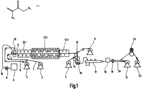
The invention is elucidated in more detail below, with reference to the
drawing. In that
drawing, Fig. 1 shows a diagrammatic representation of a device for
implementing steps
(a) to (e) of the method of the invention.
CA 02686965 2009-11-09
WO 2008/138786 PCT/EP2008/055450
11
Examples
Example 1
Fig. 1 describes an example of the solvent-free production of acrylate
adhesives. A first
release film 1, which serves as process liner, is unwound continuously from an
unwind
roll 2 and, after passing through facilities of the device, is rolled up onto
a winding roller
3. The path traveled by the release film 1 (arrow A) is determined by rollers
and rolls 4. A
coating bar 5 coats the mixture defined in step (a) of the method of the
invention onto the
release film 1. For this purpose the mixture is pumped by a regulated gear
pump 9 from a
container 8 through a hose 10 into the applicator 3 onto the release film 1.
A second release film 6 is passed through the applicator 3 as well, beneath
the top
coating bar, and so, downstream of the applicator 3, the mixture is located
between the
two release films. The second release film 6, like the release film 1, is
unwound
continuously from an unwind roller 7, guided via rollers and rolls, and
finally wound up on
a winding roll 9 following UV polymerization. The gap between the coating bars
is set
such that the polymer has a film thickness of 2 mm for a coating width of 50
cm.
The resulting three-ply laminate of release film 1, coated mixture, and
release film 6 is
subsequently passed through the UV irradiation facility 13. The double-sided
lining for the
mixture with the release films effects inertization of the mixture with
respect to
atmospheric oxygen in the course of UV irradiation. The UV irradiation
polymerizes the
mixture between the two release films. For the purpose of UV polymerization, a
plurality
of UV tubes are disposed in series in the web direction.
The heat of reaction during the UV polymerization heats up the mixture very
sharply. In
order to avoid the sudden release of the entire heat of reaction, and also in
order to attain
long polymer chains, low-pressure mercury tubes, which are of very low-
performance in
relation to medium-pressure mercury tubes, and which have UV wavelengths
tailored to
the photoinitiators used, are employed; in this case, "Cleo Performance R"
sunbed tubes
from Philips with a principal wavelength of 355 nm.
CA 02686965 2009-11-09
WO 2008/138786 PCT/EP2008/055450
12
The irradiation facility 13 has a first section 13.1 whose tunnel is traversed
by the three-
ply laminate without cooling. The first section 13.1 is followed by a second
section 13.2,
whose tunnel is cooled. Here the UV tubes are disposed between the air jets
that are
used for cooling. The second section 13.2 is followed by a third section 13.3,
which is
again uncooled. The major part of the polymerization is concluded in section
13.2. In
section 13.3, only a little heat of reaction is still released, and a
polymerization conversion
is achieved down to a residual monomer content of 0.8% to 3%.
In order to achieve sufficiently complete reaction over the depth of the
mixture it is
possible to mount UV tubes on both sides of the web. The chain length of the
polymers is
set via the intensity of the UV radiation, the operating temperature, the
distance between
the UV tubes, the web speed, and the photoinitiator content. The operational
parameters
and the formula are selected such as to minimize formation of crosslinks
between the
polymer chains.
The siliconized PET film used as release film 1 and the siliconized
polypropylene film
used as release film 6 are transparent to the UV wavelength range that is
employed.
They are used more than once.
Following the polymerization, the second release film 6 is removed and is
rolled up with
the winder 9. Located below a roller 14, which diverts the now only two-ply
laminate of
release film 1 and the polymer, is an open twin-screw extruder 16. The polymer
is drawn
in by the screws and thereby removed from the release film. In the twin-screw
extruder
16 the polymer is heated in order to lower the viscosity, and is passed via a
discharge
screw into a mixing extruder 17.
In the first part of the mixing extruder 17, residual monomers still present
are stripped off.
In the subsequent parts, resins, aging inhibitors, and UV crosslinkers are
added. The
downstream thermally conditioned holdup means 18, with a short residence time
of the
adhesive, decouples the production of acrylate adhesive from the subsequent
coating
line for adhesive tapes.
For the coating of a PP carrier having a siliconized reverse face, the
adhesive is
conveyed, using a gear pump 19 mounted in the base of the holdup means, into a
slot
CA 02686965 2009-11-09
WO 2008/138786 PCT/EP2008/055450
13
die 20. The layer thickness of the adhesive, of 25 m, is a product of the
throughput of
composition at the gear pump 19, the width of the die, and the web speed of
the coating
line. The web speed is harmonized with the flow of composition supplied from
the UV
polymerization. Coating is followed by crosslinking with a UVC dose of 45
mJ/cm2
through the UV unit 22, and by subsequent winding with the winder 23.
Example 2
All of the steps are identical to Example 1. Instead of the UV crosslinking
unit 22, though,
an electron beam installation is used for crosslinking, and a double-sided
adhesive tape
is produced with a 12 m PET carrier and two layers of composition with a
thickness
each of 150 m. To this end, coating takes place in a first operation onto a
double-sided
release paper. Following the subsequent electron-beam irradiation with a dose
of 41 kGy
at an acceleration voltage of 137 kV, winding is preceded by the lamination of
the 12 m
PET carrier onto the adhesive side (not shown). In a second operation, coating
then
takes place onto the remaining open side of the carrier, and electron-beam
irradiation
with 45 kGy at 176 kV. The electron beam installation has a titanium vacuum
window with
a thickness of 9 m, and the air gap between vacuum window and product surface
is
15 mm. The irradiation chamber is inertized with nitrogen.
Example 3
All of the steps are identical to Example 1. The twin-screw extruder 16,
though, is absent.
Instead, the polymer is removed from the release film 1 via an antiadhesive
roller and
then drawn into the mixing extruder 17 through a square opening measuring 4 x
4 cm,
which is formed by an arrangement of four driven antiadhesive rollers, via
further,
shaping antiadhesive rollers.
Example 4
All of the steps are identical to Example 1. Downstream of the third section
13.3 of the
UV irradiation facility 13, though, there is a high-powered doped medium-
pressure
mercury lamp, in order to bring the residual monomer content to an achievable
minimum.
CA 02686965 2009-11-09
WO 2008/138786 PCT/EP2008/055450
14
List of reference numerals
1 first release film (process liner)
2 unwind roller for release film 1
3 winding roller for release film 1
4 guide rolls and guide rollers for release film 1
coating bar
6 second release film
7 unwind roller for release film 6
8 container for prepolymer
9 gear pump for prepolymer
hose for composition
11 winding roller for release film 6
12 guide rolls and guide rollers for release film 6
13 UV irradiation facility
13.1 first section of the UV irradiation facility
13.2 second section of the UV irradiation facility
13.3 third section of the UV irradiation facility
14 facility for separating the release film 6
facility for separating the release film 1 (deflection roller)
16 open twin-screw extruder for drawing in and conveying the polymer
17 mixing assembly for forming the polymer/components mixture
18 holdup means for decoupling the flows of composition
19 gear pump
slot die for coating
21 unwinder, adhesive tape carrier
22 UV crosslinking unit
23 adhesive tape winder