Note: Descriptions are shown in the official language in which they were submitted.
CA 02687462 2009-11-17
WO 2009/010811 POPCT/1B2007/001974
U~
9 74
I
Packaging plant comprising at least two combined vertical forming tubes.
Field the art
The present invention refers to the packaging plants with machines having a
vertical
forming tube. The international classification of reference is B65 b and B65
d.
State of the art
It is known the circumstance that in order to increase the hourly production
of
packaging machines with vertical forming tube, the operational speed of all
the single
actuating devices of the packaging process needs to be increased. Said
increase in
operational speed necessarily implies the occurrences of accelerations that
alter the
evolution of the various phases of the technological process and the
reliability of the
different operations that necessarily need to be realized in shorter times.
The problem to be solved is that of increasing the hourly production without
increasing the operational speed of the single actuating devices that realized
the different
phases of the packaging process. The solution proposed by the present
invention doubles
the hourly production of the plant leaving unaltered the operational speed of
the single
devices that realized the different phases of the packaging process.
Description
The invention is now disclosed with reference to the figures of the drawings
attached as an unbinding example.
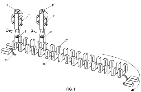
Figure 1 schematized a packaging plant comprising a single central motorized
conveyor C set up along two parallel rows of dragging devices D, D. It should
be pointed
out the fact that the dragging devices DD, D' are fed by the two vertical
forming tubes F, F'
that are especially separated and placed by the under-transiting parallel rows
of dragging
CONFIRMATION COPY
CA 02687462 2009-11-17 - V C ' T [ 120 3 7 / tl n 1 g7 4
WO 2009/010811 PCT/IB2007/001974
2
devices D, D'. Furthermore, still in figure 1, it should be noticed that the
two vertical
forming tubes F, F' are especially distanced from each other for reasons of
room
occupation. It should be pointed out that in figure 1 the two vertical forming
tubes are
represented in their initial phase when the two bags S, S' are already
packaged but not yet
cut off.
Figure 2 represents the following phase, when the first two packaged bags S,
S'
have already fallen amongst the dragging devices D, D' that set up in parallel
rows the
single central conveyor C. It should be noticed, still in figure 2, that the
bag S' has fallen a
few steps ahead of the bag S along the single conveyor C, for reasons of
overall
dimensions.
Figure 3 represents the evolution of the feeding phases of the following bags
S, S'.
It should be noticed that some bags have already been placed in both the
parallel tracks
between the dragging devices D, D', set-up on the single central motorized
transporting
conveyor C.
Figure 4 and 5 shows the unfolding of some likely operations of treatment of
the
head of the bags.
Figure 6 shows the position of the plant with both the tracks in simultaneous
production.
Figure 7 shows the phase of side removal of the parallel rows of bags S, S'
and their
possible coming near after the weight control operations P, P'.
In all figures each single detail is marked as follows:
C is a single central motorized and intermitting horizontal conveyor.
D and D' are dragging devices of the packaged bags.
CA 02687462 2009-11-17 p
WO 2009/010811 ~CT/IB2007/0019740 19 74
3
E indicates the labels applied on the folded fin of the bag.
F, F' are the vertical forming tubes.
P, P' are weight control devices.
S, S' are packaged bags.
T, T' are the dragging belts of the vertical forming tubes.
U indicates the possible operations of completing the fin.
V indicates the possible operations of trimming of said fin.
Z indicates the operations of folding of the fin and of attaching a label E
onto the
head of the bag.
The functioning of each single forming tube F, F' of the plant showed
schematically
in the attached figures can be independently managed.
The forming tubes F, F' can be fed with similar film of flexible material to
package
simultaneously identical bags containing the same amount of the same product.
In this instance, the productivity doubles compared to a known plant with a
single
row, while the operational speed of the single actuating devices of the
packaging process is
the same.
Furthermore, one of the two forming tubes can be in rest position for
different
operational needs, such as the film roll change, while the other forming tube
is kept
working under single production.
Of course the two forming tubes F, F' can be einployed to handle different
films to
package simultaneously bags by the external outlook differently customized.
CA 02687462 2009-11-17
WO 2009/010811 PPiT/~IB~O ~ ~ %9 U 019 74
4
It is obvious that the same plant can be set up with two forming tubes of
different
format to package bags that are different not only in the package but also in
the quality and
quantity of the packaged product.
It should be pointed out that the plant that forms the object of the present
industrial
invention, on top of being far cheaper than two separate plants, it also
allows a considerable
management economy not only in terms of total dimensions, but also in terms of
people
needed to operate it.
The present inventions highlights the overall versatility of the plant, that
results
optimized under all its industrial aspects.
Naturally the invention allows several variations of practical realization,
both with
respect to the dimensioning and the structural proportioning, as well as for
the
technological choices relative to the different single or grouped components.
All the packaging plants including at least two vertical forming tubes that
result
combined with a single central motorized conveyor equipped with dragging
devices
constituting several separate parallel tracks according to the number of
vertical forming
tubes, and having the features as described, showed and hereinafter claimed,
will be
considered as being part of the protection sphere of the present invention.
The inventive core on which the heuristic gradient of the present invention
rests
consists mainly in the combination of at least two vertical forming tubes with
a single
central motorized conveyor equipped with dragging devices constituting several
parallel
tracks according to the number of vertical forming tubes.