Note: Descriptions are shown in the official language in which they were submitted.
CA 02687706 2009-12-08
APPARATUS AND METHOD FOR HEAT RECOVERY
FROM ROTARY KILNS
FIELD OF THE INVENTION
The present invention relates to an apparatus and method for recovering heat
radiating
from the outer surface of a rotary kiln, such as those used to produce lime or
cement.
BACKGROUND OF THE INVENTION
In the production of lime from limestone or cement from starting ingredients,
long
cylindrical-shaped rotary kilns are often used. In the production of lime from
limestone, for
example, a charge of limestone is charged to one end of the kiln and passed
therethrough, while a
fuel is also charged along with air to support combustion, and the limestone
calcined to form
lime which is then discharged from the discharge end of the kiln. The fuel and
combustion air
are usually fed to the interior of the kiln adjacent the discharge end for the
calcined product.
Such fuels are generally gas or coal. The kiln is a long cylindrical vessel
having an outer
metallic shell with an interior surface of the shell lined with refractory
material so as to withstand
the high temperatures present within the interior of the kiln. As the material
within the kiln is
calcined, the high temperatures therein heat the steel shell through the
refractory lining and heat
is transferred through and radiates from the shell, which is lost, and is both
environmentally and
economically disadvantageous.
Heat losses through the shell of a rotary kiln represent a significant amount
of energy and
significantly increases the amount of energy input required for the production
of calcined
material in a rotary kiln.
I
CA 02687706 2009-12-08
Efforts have been made to prevent the loss of heat from such kilns and have
generally
focused on reducing the rate of heat transfer through the shell, primarily
through the use of
different refractory materials and shape of such materials inside the shell of
the kiln. There are,
however, limits to the effectiveness of internal refractory insulation,
primarily related to
temperature limitations of refractory materials and physical strengths of such
refractory materials.
It is an object of the present invention to provide an apparatus and method
for recovering
heat lost from the shell of a rotary kiln used for calcining materials.
SUMMARY OF THE INVENTION
An apparatus and method are provided for recovery of and reusing heat that
emanates
from a shell of a cylindrical-shaped rotary kiln used for calcining of charged
material, the kiln
having an axial length and an outer metallic surface.
The apparatus includes at least one enclosure of a stationary cylindrical
housing spaced
from and extending along at least a portion of the axial length of the rotary
kiln, which has an
opening extending axially therealong so as to expose a portion of the shell,
and opposed spaced
circumferential ends on the housing. Flexible closure flaps are provided along
the axially
extending opening on the circumferential ends of the housing and extend
towards the shell,
which close at least a portion of the space extending between the
circumferential ends of the
housing and the shell so as to retain heat discharged from the shell in a
chamber formed between
the shell and the housing. An exhaust fan is provided for drawing a flow of
air into the chamber,
which flow of air recovers heat from the shell and is heated in the chamber,
and which
discharges the resultant heated air from the chamber, and means are provided
to recover the heat
from the heated air discharged from the chamber.
2
CA 02687706 2009-12-08
The enclosure may be in the form of a single enclosure which preferably
extends along a
major portion of the axial length of the steel shell, or a plurality of spaced
enclosures. A single
fan may be used in conjunction with an enclosure or a plurality of fans may be
used with an
enclosure.
The flow of air is preferably drawn into the enclosure axially from axial ends
of the
housing, or seals may be provided at the axial ends of the housing and air
drawn in past flexible
closure flaps on the circumferential ends of the housing which are reduced in
size to not
completely seal against the steel shell.
The present method for recovering heat from a shell of a cylindrical-shaped
rotary kiln
having an axial length and an outer surface includes providing at least one
enclosure in the form
of a stationary cylindrical housing spaced from and extending along at least a
portion of the axial
length of the rotary kiln, the housing having an opening extending axially
therealong so as to
expose a portion of the shell, and opposed spaced circumferential ends on the
housing having
flexible closure flaps provided along the axially extending opening on the
circumferential ends
of the housing extending towards the shell, which closes at least a portion of
the space extending
between the circumferential ends of the housing and the shell so as to retain
heat discharged from
the shell in a chamber formed between the shell and the housing. A flow of air
is drawn into the
housing and through the chamber, which flow of air recovers heat from the
shell in the chamber.
Resultant heated air is discharged from the chamber, and the heat is recovered
from the heated
air discharged from the chamber.
Preferably, the flow of air is through a single enclosure which extends along
a major
portion of the axial length of the shell and heat is recovered from a major
portion of the shell,
although a plurality of such enclosures may be provided. Also, the air may, if
desired, be drawn
3
CA 02687706 2009-12-08
axially from axial ends of the housing, or past shortened flexible closure
flaps, through the
chamber.
BRIEF DESCRIPTION OF THE DRAWINGS
The present invention will be better understood by reference to the following
description
of a preferred embodiment of an apparatus of the present invention with
reference to the
accompanying drawings, wherein:
FIG. 1 is an elevational cross-sectional view of a rotary kiln having the
apparatus of the
present invention;
FIG. 2 is an enlarged elevational view of the apparatus of the present
invention associated
with a kiln;
FIG. 3 is a cross-sectional view showing the support of the apparatus;
FIG. 4 is a cross-sectional view, similar to FIG. 3, showing another
embodiment of the
apparatus of the present invention; and
FIG. 5 is an enlarged elevational view similar to FIG. 2, showing a further
embodiment
of the present invention.
DETAILED DESCRIPTION
In accordance with the present invention, an apparatus and method are provided
for
recovery of heat radiating from the outer surface of a rotary kiln. Referring
to the drawings, a
cylindrical-shaped rotary kiln 1, includes a metal shell 2 having an inner
surface 3 with a
refractory lining 4 and an outer surface 5. The rotary kiln 1 has a charging
end 6 to which a
material 7 to be calcined is charged from a source 8 through line 9, and an
enclosure 10 through
4
CA 02687706 2009-12-08
which off gases are discharged from the rotary kiln 1. At the opposite end of
the rotary kiln 1
there is a discharge housing 11 and a burner 12 that is fed with fuel and
combustion air from a
source 13. A means to rotate the kiln I is provided, such as rotatable rollers
14 on standards 15.
In producing lime, limestone, as a material 7 to be calcined is fed from
source 8 through line 9 to
the interior 16 of the kiln 1 and is conducted through the kiln 1 where it is
calcined to lime, and
the lime is discharged through housing 11, after heating to a high temperature
in the interior 16,
by a combustion flame in the range of 2600 degrees F. or more. The lime kiln
1, as described, is
conventional and does not, in itself, form part of the present invention.
Due to the high temperature in the rotary kiln, even with the use of a
refractory lining 4,
the outer surface 5 of the steel shell 2 becomes hot and radiates heat to the
surrounding area.
Recovery and reuse of the radiated heat from the steel shell would be both
economically and
environmentally advantageous.
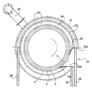
In accordance with the present invention, an apparatus 17 is provided for
recovery of heat
from the steel shell 2 of the kiln 1, which kiln has an axial length a and
outer surface 5. An
enclosure 18 is provided that has a stationary housing 19 that is spaced from
and extends along at
least a portion of the axial length a of the kiln, which housing 19 has axial
ends 20a and 20b, and
an axially extending opening 21 that exposes a portion of the outer surface 5
of the steel shell 2,
opposed circumferential ends 22a and 22b, and an inner annular wall 23. In
order to at least
partially seal a heat recovery chamber 24 between the steel shell 2 and an
inner annular wall 23,
flexible closure flaps 25 (FIG. 3) are secured to the circumferential ends 22a
and 22b of the
housing, which flaps extend towards the outer shell 2 and at least partially
seal the chamber 24.
In a preferred embodiment, the flaps substantially completely seal the chamber
24, and
preferably contact the outer shell 2. The housing is situated about the steel
shell 2 and is
CA 02687706 2009-12-08
supported by post supports 26. The inner and outer annular walls 23 preferably
have
corrugations 27 to assist in heat transfer therefrom.
An exhaust conduit 28 is connected with the chamber 24 through the annular
wall 23,
which exhaust conduit has a fan 29. The fan 29, as best shown in FIG. 2, draws
air through the
axial ends 20a and 20b and discharges the air through the exhaust conduit 28.
As the air flows
through the heat recovery chamber 24 the air is heated and the resultant
heated air from the
chamber is passed to a heat recovery device 30. The heat recovery device 30
may charge the
heated air to combustion air in source 13 through line 31, or the heated air
may be passed
through line 32 to any other heat recovery system, such as a steam generators
or other usage.
The housing of FIGS. 1-3 extends preferably along a major portion of the axial
length a
of the steel shell 2 and most preferably along about eighty (80) percent of
the axial length a. The
axially extending opening 21 is about 5-15 percent, preferably about 10
percent of the
circumference of the housing 19, in width, and allows visual inspection of the
steel shell 2 and
measurement of the shell temperature so as to estimate the condition of
refractory lining 4 and/or
spot failure in the refractory lining.
In the embodiment illustrated in FIG. 4, the axial ends of the housing 19 have
inwardly
extending sealing members 33, such as flaps or flanges, that substantially
close off the space 34
between the shell 2 and the ends of the housing 19 but leave small end opening
35 between the
shell 2 and the inner end 36 of the sealing member 33. In such an embodiment,
air is drawn into
the chamber 24 through the axially extending opening 21 in the housing 19. The
size of the
small end opening 35 will determine how much air is drawn through axially
extending opening
21 relative to air drawn in through end opening 35.
6
CA 02687706 2009-12-08
A further embodiment of the present apparatus is illustrated in FIG. 5, which
shows the
use of a plurality of spaced enclosures 18 disposed along the axial length of
a kiln and also the
use of a plurality of exhaust conduits 28 and exhaust fans with an enclosure
18.
According to the present method, an enclosure is provided for a cylindrical-
shaped rotary
kiln, the enclosure being formed as at least one stationary housing that is
spaced from and
extends along at least a portion of the axial length of the rotary kiln. The
housing has an opening
that extends axially therealong and exposes a portion of the shell of the
rotary kiln. Opposed
circumferential ends of the housing are provided with flexible closure flaps
which extend
towards the shell of the rotary kiln, and at least partially close the space
between the
circumferential ends of the housing and the kiln shell to form a chamber where
heat discharged
from the shell is retained. In order to recover the heat, a flow of air is
drawn into the housing,
such as by a fan disposed in an exhaust conduit connected to the chamber
through an annular
wall of the housing, with the flow of air being heated in the chamber to
recover heat from the
shell and the resultant heated air is discharged from the chamber through the
conduit and the heat
from the discharged air is recovered after being discharged from the chamber.
The heat from the discharged air can be recovered in a number of ways, such as
feeding
the discharged air to a combustion system for use in the rotary kiln, feeding
the air to a heat
exchanger to heat other fluids, or other heat recovery systems.
The flow of air may be drawn through a single enclosure, which preferably
extends along
a major portion of the axial length of the rotary kiln, or through a plurality
of spaced such
enclosures. Also, the flow of air may be drawn into the enclosure axially from
the ends of the
housing and through the chambers, or past shortened flexible closure flaps, or
both.
7
CA 02687706 2009-12-08
The apparatus and method disclosed herein is especially suitable for use with
rotary kilns
for use in producing lime from limestone but may be used with other rotary
kilns heated to high
temperatures, where heat is radiated from the outer surface of the kiln.
8