Note: Descriptions are shown in the official language in which they were submitted.
CA 02687796 2009-11-20
WO 2008/147784 PCT/US2008/064282
COMPOSITE TUB BODY FOR A DISHWASHER
FIELD OF THE INVENTION
The present invention pertains to the art of dishwashers and, more
particularly,
to a dishwasher tub body formed from a multi-layer composite structure.
DISCUSSION OF THE PRIOR ART
A typical dishwasher includes a tub having a fi=ont opening that leads to an
interior washing compartment and a door that pivotally mounts, in a scalable
manner,
across the front opening. Dishwasher tubs are typically foimed from reinforced
molded plastic having an inner surface provided with a finish that is
resistant to food
stains. However, tbrough exposure to certain foods over time, the inner
surface can
become discolored. In higher end dishwasher models, the tub is formed from
stamped
and welded stainless steel which is more impervious to stains.
Stamped and welded stainless steel tubs currently employed in the dishwasher
industiy are oiined from a fairly heavy gauge (0.22 - 0.26 inches; 5.59 --
6.60mm)
stainless steel material. The stainless steel material is stamped into shape
using very
expensive metal stamping equipment. The tub is formed in two parts which then
must
be both welded and crimped to achieve a water tight enclosure. The stamping
machinery includes a specific mold that fottns a patlicular tub half with each
operation. Stamping, welding and crimping the components, coupled with the
need to
change stamping molds for each dishwasher model, is a costly and time
consuming
process.
In addition to serving as the washing compartment, stainless steel tubs
provide
structural support for the dishwasher, thus the requirement for the heavy
gauge
stainless steel. However, stainless steel tubs must also be provided with
support ribs
and an exterior coating of a mastic material which acts both as a sound
deadening and
insulation layer. The need for heavy gauge steel, ribs and the requirement of
the
mastic layer further increases costs associated with the manufacturing
process.
In connection with the present invention, a need has been recognized for a
stain resistant dishwasher tub that is both easy to manufacture and modular.
The tub
would also provide any necessary sound/thermal insulation and structural
support for
the appliance.
CA 02687796 2009-11-20
WO 2008/147784 PCT/US2008/064282
SUMMARY OF THE INVENTION
The present invention is directed to a tub for a dishwasher. The dishwasher
tub includes a main body having first and second opposing side walls that are
interconnected by a rear wall. Each of the first and second opposing side
walls and
rear wall include corresponding upper and lower edge portions. In accordance
with
the invention, the opposing side and rear walls are formed from a multi-
layered
composite material. In accordance with a first embodiment of the invention,
the main
body is preferably formed from a single sheet of composite material that is
folded into
shape. In accordance with a second embodiment of the invention, each of the
first
and second opposing side walls and rear wall can also be formed separately and
joined together to form the main body. In addition, the dishwasher tub
includes a cap
member joined to the upper edge portions of the opposing side and rear walls,
as well
as a base member joined to the lower edge portion of each of the first and
second
opposing side walls and rear wall. The main body, coupled with the cap and
base
members, define an overall washing chamber having a front opening.
Preferably, the multi-layered composite material includes a stainless layer, a
rigid layer and a protective layer. More specifically, the stainless layer is
preferably
foi7ned from thin (0.05 - 0.08 inches; 1.27 -T- 2.03mm) gauge stainless steel
and
defines an interior surface of the tub. The rigid layer is preferably formed
from a
polyester mat, most preferably VERSAMAT produced by Owens Corning, which
provides both structural integrity and sound insulation for the tub. The
outer,
protective, layer is formed from hard plastic, aluminum foil or the like. The
outer
layer, in addition to adding to the overall structural support of the tub,
also preferably
serves, at least in part, as a shipping container for the dishwasher. In this
manner,
components of the dishwasher can be constructed in various locations then
readily and
inexpensively transported to a control location for final assembly.
Additional objects, features and advantages of the present invention will
become more readily apparent from the following detailed description of
preferred
embodiments when taken in conjunction with the drawings wherein like reference
numerals refer to cotTesponding parts in the several views.
2
CA 02687796 2009-11-20
WO 2008/147784 PCT/US2008/064282
BRIEF DESCRIPTION OF THE DRAWINGS
Fig. 1 is a right perspective view of a dishwasher including a tub formed from
a multi-layered composite material constructed in accordance with the present
invention;
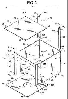
Fig. 2 is an exploded view of a dishwasher tub of the present invention;
Fig. 3 is a perspective view of a main body portion of the dishwasher tub of
Fig. 2;
Fig. 4 is a perspective view of a main body portion of the dishwasher tub
constructed in accordance with another embodiment othe present invention; and
l0 Fig. 5 is a cross-sectional side view of the multi-layered composite
material of
the present invention.
DETAILED DESCRIPTION OF THE PREFERRED EMBODIMENTS
With initial reference to Fig. 1, a dishwasher, constructed in accordance with
the present invention, is generally indicated at 2. Dishwasher 2 is shown to
include a
washing chamber 4 defined by a tub 6. A door 7 is pivotally mounted to
dishwasher 2
to selectively expose washing chamber 4 to enable a user to load and unload
kitchenware. In the embodiment shown, dishwasher 2 is arranged below a
countertop
8 adjacent cabinetry 12. In a manner known in the art, dishwasher 2 includes a
plurality of dish racks 15 and 16 for supporting the kitchenware and a wash
arm 18,
fluidly connectcd to a pump 21, which sprays jets of washing fluid onto the
kitchenware (not shown) during a washing operation.
In accordance with the invention, tub 6 is constructed from a multi-layered
composite material as will be discussed more fully below. As best shown in
Fig. 2,
tub 6 includes a main body 57 having first and second opposing side walls 60
and 61
interconnected through a rear wall 62. First side wall 60 includes upper and
lower
edge poitions 64 and 65 and outer edge portions 66 and 67. Likewise, second
opposing side wall 61 includes upper and lower edge portions 68 and 69, as
well as
outer edge portions 70 and 71. Rear wal162 includes upper and lower edge
portions
72 and 73 and outer edge portions 74 and 75 that adjoin outer edge portions 67
and 71
of first and second opposing side walls 60 and 61 respectively.
Tub 6 further includes a top wall or cap member 80 which can be formed fiom
stainless steel, plastic or a combination thereof depending upon the
dishwasher model.
3
CA 02687796 2009-11-20
WO 2008/147784 PCT/US2008/064282
Cap member 80 includes a generally rectangular horizontal planar portion 81
that is
provided with a plurality of openings 85-88 at corner portions thereof. The
puipose
of openings 85-88 will be discussed more fully below. Tub 6 fuither includes a
bottom wall or base member 93 which, in a manner similar to that described
above, is
preferably formed from stainless steel, plastic or a combination thereof. Base
member
93 includes a generally horizontal planar portion 94 provided with a central
opening
96 for receiving pump 21 and a plurality of openings 97-100 which align with
openings 85-88 on cap member 80.
In accordance with the embodiment illustrated in Fig. 2, tub 6 further
includes
a door halo member 107 having first and second upstanding side members 109 and
110 that are interconnected by an upper cross member 112. Door halo member 107
provides a finished appearance for tub 6 while also serving as a sealing
surface for
door 7. In any event, first side member 109 includes first and second end
opposing
portions 115 and 116. Likewise, side member 110 includes first and second end
opposing pottions 117 and 118. Each end por-tion 115-118 includes a
corresponding
tab member 121-124 configured to be received by openings 85 and 86 on cap
member
80 and openings 97 and 98 on base member 93. In addition to door halo member
107,
tub 6 includes a pair of columns 130 and 131 arranged at a rear portion
thereof.
Columns 130 and 131 are preferably foi7ned from a fiberglass reinforced
material,
most preferably from VERSAGLASS sold by Owens Corning. The particular details
of VERSAGLASS can be found in commonly owned, co-pending U.S. Patent
Publication No. 2003-017613 1, entitled "Insulating Material", published
Septembcr
18, 2003.
As shown, column 130 includes first and second opposing end portions 133
and 134 that are joined through an intermediate portion 135. Likewise, column
131
includes first and second opposing end portions 136 and 137 that are joined
through
an intermediate portion 138. Each column 130, 131 preferably has a generally L-
shaped cross-section and, as will be discussed more fully below, designed to
provide
support along outer edge portions (not separately labeled) of tub 6. In
addition, each
end portion 133, 134 of column 130 and each end portion 136, 137 of column 131
is
provided with a corresponding tab member 140-143 configured to be received by
corresponding ones of openings 87 and 88 in cap member 80 and openings 99 and
100 in base member 93 as will be discussed more fully below.
4
CA 02687796 2009-11-20
WO 2008/147784 PCT/US2008/064282
In accordance with one aspect of the invention illustrated in Fig. 3, main
body
57 can be formed from a single sheet 150 of multi-layered composite material,
having
upper and lower edge portions 155 and 158, that is bent along first and second
fold
lines 160 and 161 to create first and second opposing side walls 60 and 61 and
rear
wall 62. Preferably, fold lines 160 and 161 are established by creating
notches (not
shown) that extend between edge portions 155 and 158 on an outside surface
(not
separately labeled) of sheet 150. In this manner, no additional sealing is
required
between side walls 60 and 61 and rear wall 62. More specifically, after
forming the
notches in sheet 150, first side wa1160 is folded so as to extend
substantially
lo perpendicularly from rear wall 62. Next, second opposing side wall 61 is
folded
along fold line 161 so as to cxtend generally perpendicularly from rear wall
62, as
well as parallel to side wall 60.
After forming main body 57, base member 93 is joined to lower edge portions
65, 69 and 73 of first and second side walls 60 and 61 and rear wall 62. Base
member
93 is preferably secured to main body 57 through a crimping process. Of
course,
various welding techniques and/or adhesives could also be employed. At this
point,
door halo member 107 is positioned along and joined to outer edge portions 66
and 70
of first and second side walls 60 and 61 respectively, with tab members 122
and 124
being received by openings 97 and 98, Once properly positioned, door halo
member
107 is joined to edge portions 66 and 70 through crimping, welding, adhesive
or the
like. Once door halo 107 is in position, tab members 141 and 143 of columns
130 and
131 are inserted into openings 99 and 100 respectively. Columns 130 and 131
are
then flexed so as to provide a squeeze-fit type arrangement along the outer
edge
portions 74 and 75 of tub 6. Once door halo member 107 and columns 130 and 131
are properly positioned, cap member 80 is joined to upper edge portions 64, 68
and 72
of first and second opposing side walls 60 and 61 and rear wa1162. More
specifically,
openings 85 and 86 are aligned with corresponding ones of tab members 121 and
123
and openings 87 and 88 are aligned with respective ones of tab members 140 and
142.
Once properly aligned, cap member 80 is seated upon upper edge portions 64, 68
and
72 and joined to side walls 60 and 61, along with rear wall 62, in a manner
similar to
that described above with respect to base member 93. Once completed, tub 6 is
integrated into dishwasher 2 during final assembly.
5
CA 02687796 2009-11-20
WO 2008/147784 PCT/US2008/064282
In accordance with another embodiment of the invention as illustrated in Fig.
4, a tub 6' is formed from a plurality of distinct sheets of multi-layered
composite
material. More specifically, first and second opposing side walls 60' and 61'
are
joined to a rear wa1162'. In a manner similar to that described above, first
side wall
60' includes upper and lower edge portions 64' and 65, as well as first and
second
opposing outer edge portions 66' and 67'. Likewise, side wa1161' includes
upper and
lower edge portions 68' and 69', as well as opposing outer edge portions 70'
and 71'.
Rear wall 62' includes upper and lower edge portions 72' and 73' and opposing
outer
edge poilions 74' and 75'. With this construction, outer edge portion 67' of
side wall
61' is joined to outer edge portion 74' of rear wall 62' through a crimping
process to
form a joint 165. Likewise, outer edge portion 71' of side wall 61' is joined
to outer
edge portion 75' of rear wall 62 to form ajoin 166 in a similar manner to foim
a main
body 57'. At this point, tub 6 is consti-ucted substantially similarly to that
described
above with cap member 80 being joined to upper edge portions 64', 68' and 72',
and
base member 93 being connected to lower edge portions 65', 69' and 73'. Door
halo
member 107 and columns 130 and 131 are also connected in a manner similar to
that
described above.
As noted above, tub 6 is formed from a multi-layered composite material. As
best shown in Fig. 5, the multi-layered composite material includes a first or
inner
layer 185, a second or intermediate layer 186 and a third or outer layer 187.
Inner
layer 185 is preferably formed fi=om thin (approx. 0.05 -W- 0.08 inch; 1.27 -
2.03mm)
gauge stainless steel and represents an interior surface of tub 6.
Intetmediate layer 2
is preferably a polyester fiber reinforced mat, such as VERSAMAV) made by
Owens
Corning, which provides both structural support and sound insulation for
dishwasher
2. The particular details of VERSAMAT1~ can be found in commonly owned, co-
pending U.S. Patent Publication No. 2003-0176131, entitled "Insulating
Material",
published September 18, 2003.
Third layer 187 defines a protective layer for tub 6 and is preferably formed
from hard plastic, aluminum foil or the like. With this construction, the
multi-layered
composite material minimizes thermal loss from tub 6 thereby eliminating the
need
for any additional insulation layers or sound deadening blankets about
dishwasher 2.
In addition, the multi-layered composite material provides structural
reinforcement to
tub 6 thereby eliminating the need for additional reinforcing members such as
ribs,
6
CA 02687796 2009-11-20
WO 2008/147784 PCT/US2008/064282
frames and the like. Moreover, the use of columns 130 and 131 and door halo
107
further add to the overall structural integrity of the dishwasher. Columns 130
and 131
and door halo 107 also provide protection to vulnerable portions of dishwasher
2
thereby eliminating the need for shipping containers which totally encapsulate
the
dishwasher. It should also be understood that the present invention provides a
modular, cost-efficient component for dishwashers which can be constructed in
various locations and readily transported to a central location for final
assembly and
shipment to wholesalers, consumers, etc. The multi-layered composite material
also
eliminates the need for expensive stamping machinery and reduces the number of
welding and crimping operations required to produce a dishwasher tub. Finally,
the
multi-layered composite material can be formed in a variety of shapes so as to
accommodate various dishwasher models. In this manner, there would be no need
to
halt production, retool and start another production line for a different
dishwasher
model. Thus, the present invention enables a manufacturer to produce short
production runs of dishwasher tubs in a time and cost efficient manner.
7