Note: Descriptions are shown in the official language in which they were submitted.
CA 02688126 2009-12-07
1
Description
Title of Invention
CO2 Recovering Apparatus and Method
Technical Field
[0001]
The present invention relates to a CO2 recovering
apparatus and a CO2 recovering method that enable a CO2
absorbent concentration to be kept constant to maintain
absorbing performance thereof.
Background Art
[0002]
It has come to be pointed out that one of the causes
of the global warming is a greenhouse effect of C02, and it
has became an urgent task, also internationally, to provide
a countermeasure for CO2 to protect the global environment
against the warming. CO2 is generated by any human
activities combusting fossil fuels, and there are
increasing demands for suppressing CO2 emissions. Along
with such an increasing demand, researchers are
energetically investigating a method for reducing and
recovering CO2 included in flue gas, to apply in a power
plant that consumes a large amount of fossil fuels, such as
a thermal plant. In such a method, flue gas emitted from a
steam generator is brought into contact with an amine-based
CO2 absorbent to allow such absorbent to absorb the CO2,
and the recovered CO2 is stored therein without being
released into the air. As processes for reducing and
recovering CO2 from the flue gas using the CO2 absorbent,
Japanese Patent Application Laid-open No. H3-193116, for
example, brings flue gas into contact with the CO2
CA 02688126 2009-12-07
2
absorbent in an absorber, heats an absorbent that has
absorbed CO2 in a regenerator, isolates CO2 as well as
regenerates the absorbent, and circulates the absorbent
back to the absorber and reuses the absorbent therein.
Background Art
[0003]
Fig. 5 is a schematic of an example of a conventional
CO2 recovering apparatus. As shown in Fig. 5, a
conventional CO2 recovering apparatus 100 as mentioned
above includes a flue gas cooler 14, a CO2 absorber 16, and
a regenerator 18. The flue gas cooler 14 cools flue gas 12
containing CO2 and 02 emitted from an industrial combustion
facility 11, such as a steam generator or a gas turbine,
with cooling water 13. The CO2 absorber 16 further
includes a CO2 recovering unit 16A. The CO2 recovering
unit 16A brings the flue gas 12, containing the cooled C02,
into contact with CO2 absorbent (hereinafter, also referred
to as "absorbent") 15 that absorbs CO2, to reduce CO2 in
the flue gas 12. The regenerator 18 causes CO2 absorbent
(hereinafter, also referred to as "rich solvent") 17 that
has absorbed CO2 to release CO2 to regenerate the CO2
absorbent.
In the CO2 recovering apparatus 100, the regenerated
CO2 absorbent (hereinafter, also referred to as "lean
solvent") 15 having CO2 reduced in the regenerator 18 is
reused in the CO2 absorber 16 as the CO2 absorbent.
[0004]
By a CO2 recovering method using the CO2 recovering
apparatus 100, a flue gas booster fan 20 raises the
pressure of the flue gas 12 emitted from an industrial
combustion facility such as a steam generator or a gas
turbine and containing CO2. The flue gas 12 is then sent
CA 02688126 2009-12-07
3
into the flue gas cooler 14, cooled by way of the cooling
water 13, and then sent into the CO2 absorber 16.
[0005]
The C02 absorber 16 then brings the flue gas 12 in a
counter-current contact with the C02 absorbent 15 that is
based on amine-based solvent, allowing the CO2 absorbent 15
to absorb the CO2 contained in the flue gas 12 by way of
chemical reaction.
A washing unit 16B, included in the CO2 absorber 16,
brings the flue gas having C02 reduced in the C02
recovering unit 16A into a gas-liquid contact with
circulating condensate water 19. The condensate water 19
contains the C02 absorbent, and is supplied via a nozzle
included in a washing unit 16B. In this manner, the C02
absorbent 15 that has accompanied the flue gas having CO2
reduced is recovered. Flue gas 12 having C02 reduced is
released out of the system.
A rich solvent pump 22 increases the pressure of the
rich solvent that is the C02 absorbent 17 that has absorbed
CO2. Then, a rich/lean solvent heat exchanger 23 heats the
rich solvent by way of the CO2 absorbent 15 that is lean
solvent regenerated by the regenerator 18, and supplied
into the regenerator 18.
[0006]
The rich solvent discharged into the regenerator 18
through the top thereof causes an endothermic reaction,
thus releasing a majority of CO2. The C02 absorbent that
has released some or a majority of CO2 in the regenerator
18 is called semi-lean solvent. By the time the semi-lean
solvent reaches the bottom of the regenerator 18, almost
all of the CO2 is removed, turning the semi-lean solvent
into the absorbent 15. A regenerating heater 24 then heats
the lean solvent by way of steam 25, supplying steam inside
CA 02688126 2009-12-07
4
the regenerator 18.
CO2 gas 26 is guided out from the top of the
regenerator 18, together with the steam that has been
released from the rich solvent and semi-lean solvent in the
regenerator 18. A condenser 27 then condenses steam
contained in the CO2 gas 26, and a separation drum 28
separates water from the CO2 gas 26. The CO2 gas 26 is
then released out of the system, and recovered separately.
The recovered CO2 gas 26 is injected into an oilfield using
enhanced oil recovery (EOR) method, or stored in an aquifer
as a countermeasure for global warming.
The water separated in the separation drum 28 is
pumped up to the top of the regenerator 18 by way of a
condensed-water circulating pump 29. The rich/lean solvent
heat exchanger 23 cools the regenerated CO2 absorbent (lean
solvent) 15 by way of the rich solvent 17. A lean solvent
pump 30 then increases the pressure of the lean solvent 15.
After being cooled down by a lean solvent cooler 31, the
lean solvent 15 is supplied into the CO2 absorber 16.
[0007]
In Fig. 5, the reference numeral lla denotes to a flue
for the flue gas 12; the reference numeral l1b denotes to a
stack; and the reference numeral 32 denotes to steam-
condensed water. The CO2 recovering apparatus may be
either added to an existing flue gas source to recover C02,
or installed with a flue gas source that is to be newly
installed. A door that can be opened and closed is
attached on the stack 11b. The door is closed while the
CO2 recovering apparatus is operating, and opened while the
flue gas source is operating but the CO2 recovering
apparatus is not operating.
[0008]
If the CO2 recovering apparatus is kept running,
CA 02688126 2009-12-07
recovering CO2 and consuming the CO2 absorbent, the
concentration of the absorbent drops. Because the
concentration reduction is by approximately 10 percent in a
relative ratio with respect to a set value, according to a
conventional technology, high concentration absorbent is
added as appropriate.
[0009]
Furthermore, as disclosed in Japanese Patent
Application Laid-open No. 2001-252524, conventionally, a
tower bottom liquid level controller is provided in the CO2
absorber 16 to keep the absorbent concentration constant,
and to control a circulating water return temperature in
the washing unit 16B to adjust an amine concentration of
the absorbent.
Citation List
Patent Literature
[0010]
PATENT LITERATURE 1 Japanese Patent Application Laid-open
No. H3-193116
PATENT LITERATURE 2 Japanese Patent Application Laid-open
No. 2001-252524
Summary of Invention
Technical Problem
[0011]
According to the suggestion disclosed in the Japanese
Patent Application Laid-open No. 2001-252524, the absorbent
concentration can be kept constant if the adjustment spans
for a short term (e.g., a few days); however, if the
operation is kept running for a long time (e.g., one to
four weeks or longer), the absorbent concentration
gradually drops and is attenuated. In such a situation,
CA 02688126 2009-12-07
6
high concentration absorbent needs to be added to keep the
concentration to a predetermined level.
[0012]
The present invention is made in consideration of the
above, and an object of the present invention is to provide
a C02 recovering apparatus and a C02 recovering method that
can keep C02 absorbent concentration constant over a long
time.
Solution to Problem
[0013]
According to an aspect of the present invention, a CO2
recovering apparatus including a CO2 absorber that brings
flue gas containing C02 into contact with a CO2 absorbent
to reduce the C02 contained in the flue gas, and a
regenerator that reduces CO2 contained in rich solvent
absorbing CO2 in the C02 absorber to regenerate the rich
solvent, so that lean solvent that is the C02 absorbent
having the CO2 reduced in the regenerator is reused in the
CO2 absorber, includes a controller that detects a
difference between a temperature of gas entering the C02
absorber and that of gas exiting the C02 absorber, and an
absorbent concentration of the C02 absorbent, and controls
the absorbent concentration of the CO2 absorbent within a
set range by adjusting an amount of water contained in the
gas depending on the difference between the temperature of
the gas entering the CO2 absorber and that of the gas
exiting the C02 absorber to.
[0014]
Advantageously, the C02 recovering apparatus further
includes a C02 absorbent level meter disposed in a bottom
liquid depository of the CO2 absorber. A C02 absorbent of
a set concentration is supplied when a liquid level drops.
CA 02688126 2009-12-07
7
[0015]
Advantageously, in the CO2 recovering apparatus, the
temperature of the gas entering the 002 absorber and that
of the gas exiting the absorber, and the absorbent
concentration and the liquid level of the CO2 absorbent are
detected, and the liquid level is lowered incrementally,
and the CO2 absorbent of the set concentration is supplied
into a system when the liquid level reaches a lowest set
level, while keeping the temperature of the gas exiting the
002 absorber within a predetermined range.
[0016]
According to another aspect of the present invention,
a CO2 recovering method using a CO2 absorber that brings
flue gas containing 002 into contact with a CO2 absorbent
to reduce the CO2 contained in the flue gas, and a
regenerator that reduces CO2 contained in rich solvent
absorbing CO2 in the CO2 absorber to regenerate the rich
solvent, so that lean solvent that is the 002 absorbent
having the CO2 reduced in the regenerator is reused in the
CO2 absorber, includes detecting a difference between a
temperature of gas entering the CO2 absorber and that of
gas exiting the CO2 absorber, and an absorbent
concentration of the CO2 absorbent, and controlling the
absorbent concentration of the 002 absorbent within a set
range by adjusting an amount of water contained in the gas
depending on the difference between the temperature of the
gas entering the CO2 absorber and that of the gas exiting
the CO2 absorber.
Advantageous Effects of Invention
[0017]
According to one aspect of the present invention, even
if the operation is continued for a long time, the
CA 02688126 2011-12-19
8
absorbent concentration can be kept constant to maintain the
absorbing performance thereof.
[00181
Furthermore, because the level meter is provided in the
liquid depository of the 002 absorber, the liquid level can also be
kept constant.
Accordingly, in one aspect, the present invention resides in
a 002 recovering apparatus including a 002 absorber that brings flue
gas containing 002 into contact with a 002 absorbent to reduce the
002 contained in the flue gas, and a regenerator that reduces 002
contained in rich solvent absorbing 002 in the 002 absorber to
regenerate the rich solvent, so that lean solvent that is the 002
absorbent having the 002 reduced in the regenerator is reused in
the 002 absorber, comprising: a controller that detects a
difference between a temperature of gas entering the 002 absorber
and that of gas exiting the 002 absorber, and an absorbent
concentration of the 002 absorbent, and controls the absorbent
concentration of the 002 absorbent within a set range by adjusting
an amount of water contained in the exiting gas depending on the
difference between the temperature of the gas entering the 002
absorber and that of the gas exiting the 002 absorber, wherein the
apparatus further comprises a 002 absorbent level meter dsposed in
a bottom liquid depository of the C02absorber, and a 002 absorbent
supply for supplying a 002 absorbent of a set concentration when a
liquid level drops in the C02absorber.
In another aspect, the present invention resides in a 002
recovering method using a 002 absorber that brings flue gas
containing 002 into contact with a 002 absorbent to reduce the 002
contained in the flue gas, and a regenerator that reduces 002
contained in rich solvent absorbing 002 in the 002 absorber to
regenerate the rich solvent, so that lean solvent that is the 002
absorbent having the 002 reduced in the regenerator is reused in
CA 02688126 2011-12-19
8a
the 002 absorber, comprising: detecting a difference between a
temperature of gas entering the 002 absorber and that of gas
exiting the 002 absorber, and an absorbent concentration of the 002
absorbent; and controlling the absorbent concentration of the 002
absorbent within a set range by adjusting an amount of water
contained in the gas depending on the difference between the
temperature of the gas entering the 002 absorber and that of the
gas exiting the 002 absorber, wherein the method further comprises
disposing a 002 absorbent level meter in a bottom liquid depository
of the 002 absorber, and supplying a 002 absorbent of a set
concentration when a liquid level drops in the 002 absorber.
Brief Description of Drawings
[0019]
Fig. 1 Fig. 1 is a schematic of a 002 recovering apparatus
according to a first embodiment of the present invention.
Fig. 2 Fig. 2 is a schematic of a relationship between an
operation time of the 002 recovering apparatus according to the
first embodiment and a ratio of a set concentration of the
absorbent.
Fig. 3 Fig. 3 is a schematic of a relationship between an
operation time of a conventional 002 recovering apparatus and a
ratio of the set concentration of the absorbent.
Fig. 4 Fig. 4 is a schematic of a 002 recovering apparatus
according to a second embodiment of the present invention.
Fig. 5 Fig. 5 is a schematic of an example of the conventional
002 recovering apparatus.
Description of Embodiments
[0020]
Embodiments of the 002 recovering apparatus according to the
present invention will now be explained in detail with reference to
the drawings. The embodiments herein are not intended to limit the
scope of the present invention in any way.
CA 02688126 2009-12-07
9
Example 1
[0021]
A first embodiment of the CO2 recovering apparatus
according to the present invention will be explained with
reference to Fig. 1.
Fig. 1 is a schematic of a structure of the CO2
recovering apparatus according to the first embodiment. In
Fig. 1, the same structures as those included in the CO2
recovering apparatus shown in Fig. 5 are given the same
references signs, and the redundant explanations thereof
are omitted herein.
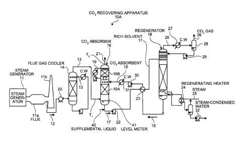
As shown in Fig. 1, a CO2 recovering apparatus 10A
according to the first embodiment includes the CO2 absorber
16 that brings the flue gas 12 containing CO2 into contact
with the CO2 absorbent 15 to reduce the CO2 contained in
the flue gas 12; the regenerator 18 that reduces CO2
contained in the rich solvent 17 that has absorbed CO2 in
the CO2 absorber 16 to regenerate the rich solvent 17, so
that the lean solvent that is the CO2 absorbent 15 having
CO2 reduced in the regenerator 18 is reused in the CO2
absorber 16; and a controller that detects a gas
temperature difference between a temperature (T1 (e.g.,
approximately 40 Celsius degrees)) of the flue gas 12 that
is guided into an entrance of the CO2 absorber 16 at such
an entrance and a temperature (T2 (e.g., 40 approximately
Celsius degrees)) of the exiting gas 21 in the CO2 absorber
16, and an absorbent concentration (X (Vol%)) of the CO2
absorbent 15, and controls to adjust an amount of water
depending on the gas temperature difference between the
entering gas and the exiting gas 21 in the CO2 absorber 16
to keep the absorbent concentration of the CO2 absorbent 15
within a set range (e.g., XO 10% in a relative ratio).
CA 02688126 2009-12-07
The entering gas temperature of the flue gas 12 (T1
(approximately 40 Celsius degrees)) and the temperature of
the exiting gas 21 (T2 (approximately 40 Celsius degrees))
are measured by thermometers not shown, and communicated to
a controlling apparatus not shown as well.
The gas temperature of the entering flue gas 12 (T1
(approximately 40 Celsius degrees or so)) is measured to
confirm that flue gas is guided into the C02 absorber 16
properly under an initial condition.
[0022]
According to the first embodiment, to control to keep
the absorbent concentration of the CO2 absorbent 15 within
a set range (for example, X 10% in a relative ratio), the
exiting gas temperature (T2) is increased when the amount
of water needs to be reduced.
In this manner, the concentration of the CO2 absorbent
can be kept constant, and the CO2 absorbing performance
thereof can be maintained.
[0023]
To detect the absorbent concentration (X (Vol%)) of
the CO2 absorbent 15, the C02 absorbent 15 is sampled and
analyzed. An initial concentration is herein denoted as
Xo; the first measurement is denoted as X1; and the second
measurement is denoted as X2. The analysis may be
performed either manually or automatically.
[0024]
A specific example of an operation of the CO2
recovering apparatus will now be explained.
(1) The temperature of the flue gas 12 guided into the
entrance of the CO2 absorber 16 and that of the exiting gas
21 in the C02 absorber 16 are measured.
The CO2 absorbent 15 is sampled, and the first
measurement is conducted. The result of the first
CA 02688126 2009-12-07
11
measurement is herein denoted as the concentration X1.
(2) Based on the concentration X1 that is the measurement
result, if the concentration X1 is within the set range
(e.g., X l%), the controlling apparatus not shown controls
to maintain the operation as it is.
(3) Such a measurement is conducted in every predetermined
time. It is assumed herein that, in the third measurement,
the CO2 absorbent 15 is sampled to obtain the concentration
X3 that is the third measurement result.
(4) Based on the concentration X3 that is the measurement
result, if it is determined that the concentration X3
deviates from the set range (e.g., X 1%) (for example, the
concentration drops), the controlling apparatus performs a
control to raise the exiting gas temperature (T2). By way
of this control, the water accompanying the flue gas 21
having CO2 reduced is increased by a controller not shown.
As a result, the amount of water flowing down in the CO2
absorber 16 is reduced, recovering the concentration of the
CO2 absorbent 15 into the set range (e.g., X 1%).
In this manner, it is possible to prevent a
deterioration of the absorbing performance due to the
concentration reduction in the absorbent caused by
continuous operation of the C02 recovering apparatus.
[0025]
A level meter 41 is provided in the bottom liquid
depository of the CO2 absorber 16 to measure the level of
the absorbent. If the level of the liquid becomes equal to
or lower than a predetermined value, a supplemental liquid
42 of a specified concentration (e.g., X) is supplied into
the CO2 absorbent.
In this manner, the liquid level can be kept constant,
and the concentration of the absorbent can also be kept
CA 02688126 2009-12-07
12
within a predetermined specified range.
[0026]
A relationship between the operation time of the CO2
recovering apparatus and a ratio of a set concentration of
the absorbent will now be explained for the scenario of the
present invention (Fig. 2) and for the scenario of the
conventional technology (Fig. 3) disclosed in the Japanese
Patent Application Laid-open No. 2[001-252524.
As shown in Fig. 2, according to the present invention,
upon confirming that the liquid level drops to a
predetermined level by way of the level meter 41, the
supplemental liquid 42 of the specified concentration (e.g.,
X) is supplied into the CO2 absorbent to keep the liquid
level constant, as indicated in the relationship between
the operation time and the ratio of the set concentration
of the absorbent shown in Fig. 2.
More specifically, as shown in Fig. 2, by conducting
several fine controls within a day, the concentration of
the CO2 absorbent can be kept to a constant level, and to a
constant concentration.
[0027]
In contrast, according to the conventional technology
shown in Fig. 3, an absorbent of high concentration is
supplied once a week to maintain the concentration. During
the time, the concentration of the absorbent becomes
gradually low, deteriorating the performance of the
absorbent. Therefore, to recover a predetermined amount of
C02, a larger amount of the steam 25, supplied in the
regenerating heater 24, will be used to release CO2 (an
increase by approximately 3%), thus reducing the heat
efficiency.
[0028]
The level meter 41, shown in Fig. 1, may also be
CA 02688126 2009-12-07
13
designed to measure a plurality of levels to lower the
absorber level within a plurality of ranges (for example,
the levels may be set to five stages L1, L2 ... L5) while
keeping the exiting gas temperature (T2) of the CO2
absorber 16 within a predetermined range. In this scenario,
when the absorber level reaches the lowest set level (L5),
the controlling apparatus controls to supply the CO2
absorbent 15 of the specified concentration (e.g., X 10% in
a relative ratio) into the system. In this manner, even
when the liquid level gradually lowers (from L1 to L5), the
concentration of the absorbent can be kept within a
constant range, while maintaining the absorbing performance
thereof.
Example 2
[0029]
A CO2 recovering apparatus according to a second
embodiment of the present invention will now be explained
with reference to Fig. 4.
Fig. 4 is a schematic of a structure of the CO2
recovering apparatus according to the second embodiment.
In Fig. 4, the same structures as those included in the CO2
recovering apparatus shown in Fig. 1 are given with the
same references signs, and redundant explanations thereof
are omitted herein.
As shown in Fig. 4, the CO2 recovering apparatus 10B
according to the second embodiment includes an absorbent
concentration analyzing meter 43 that analyzes the
concentration of the CO2 absorbent 15 that is the lean
solvent regenerated in the regenerator 18.
[0030]
As disclosed in Japanese Patent Application Laid-open
No. H11-258160, examples of the absorbent concentration
CA 02688126 2009-12-07
14
analyzing meter 43 include a liquid chromatograph analyzer
and a laser Raman analyzer.
A measurement result of the absorbent concentration
analyzing meter 43 may be sent to the controlling apparatus
not shown to automate a measurement and a control of the
absorbent concentration.